manuals.online logo
Brands
  1. Home
  2. •
  3. Brands
  4. •
  5. Kenwood
  6. •
  7. Receiver
  8. •
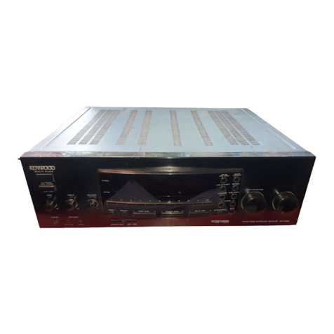
  9. Kenwood KR-V6090 User manual

Kenwood KR-V6090 User manual

KENWOOD
KR-V6090
KR-V5090
INSTRUCTION
MANUAL
KENWOOD
CORPORATION
This
manual
contains
instructions
for
two
models.
Model
availability
and
features
.
(functions)
may
differ
depending
on
country
and
sales
area.
B60-2988-00
CS
(T)
imc:
98/12
111098765432197/12
11109876
KR-V60S90/KR-VS5090
(En)
B.
ef
or
e
a
/
mn
ower
Ay,
Caution
:Read
this
section
carefully
to
ensure
safe
operation
Units
are
designed
for
operation
as
follows.
Europe
and
U.K.
.......c00cccccescsceeeee
a
cere
eee
AC
230
V
only
For
the
United
Kingdom
Factory
fitted
moulded
mains
plug
1.
The
mains
plug
contains
a
fuse.
For
replacement,
use
only
a
13-Amp
ASTA-approved
(BS1362)
fuse.
2.
The
fuse
cover
must
be
refitted
when
replacing
the
fuse
in
the
moulded
plug.
3.
Do
not
cut
off'the
mains
plug
from
this
equipment.
If
the
plug
fitted
is
not
suitable
for
the
power
points
in
your
home
or
the
cable
is
too
short
to
reach
a
power
point,
then
obtain
an
appropriate
safety
approved
extension
lead
or
adapter,
or
consult
your
dealer.
If
nonetheless
the
mains
plug
is
cut
off,
remove
the
fuse
and
dispose
of
the
plug
immediately,
to
avoid
a
possible
shock
hazard
by
inadvertent
connection
to
the
mains
supply.
Y
IMPORTANT:
The
wires
in
the
mains
lead
are
coloured
in
accordance
with
the
following
code:
Blue:
Neutral
Brown:
Live
Do
not
connect
those
leads
to
the
earth
términai
of
a
three-pin
plug.
Safety
precautions
WARNING:
TO
PREVENT
FIRE
OR
ELECTRIC
SHOCK,
DO
NOT
EXPOSE
THIS
APPLIANCE
TO
RAIN
OR
MOISTURE.
CAUTION
CAUTION:
TO
REDUCE
THE
RISK
OF
ELECTRIC
SHOCK,
DO
NOT
REMOVE
COVER
(OR
BACK).
NO
USER-SERVICEABLE
PARTS
INSIDE,
REFER
SERVICING
TO
QUALI-
RISK
OF
ELECTRIC
SHOCK
DO
NOT
OPEN
FIED
SERVICE
PERSONNEL.
THE
LIGHTNING
FLASH
WITH
ARROWHEAD
SYMBOL,
WITHIN
AN
EQUILATERAL
TRIANGLE,
IS
IN-
TENDED
TO
ALERT
THE
USER
TO
THE
PRESENCE
OF
UNINSULATED
"DANGEROUS
VOLTAGE”
WITHIN
THE
PRODUCT'S
ENCLOSURE
THAT
MAY
BE
OF
SUFFICIENT
MAGNITUDE
TO
CONSTITUTE
A
RISK
OF
ELECTRIC
SHOCK
TO
PERSONS.
THE
EXCLAMATION
POINT
WITHIN
AN
EQUILATERAL
TRIANGLE
IS
INTENDED
TO
ALERT
THE
USER
TO
THE
PRESENCE
OF
IMPORTANT
OPERATING
AND
MAINTENANCE
(SERVICING)
INSTRUCTIONS
IN
THE
LITERATURE
ACCOMPANYING
THE
APPLIANCE.
Unpack
the
unit
carefully
and
make
sure
that
all
accessories
are
put
aside
so
they
will
not
be
lost.
Examine
the
unit
for
any
possibility
of
shipping
damage.
If
your
unit
is
damaged
or
fails
to
operate,
notify
your
dealer
immediately.
If
your
unit
was
shipped
to
you
directly,
notify
the
shipping
company
without
delay.
Only
the
consignee
(the
person
or
company
receiving
the
unit)
can
file
a
claim
against
the
carrier
for
shipping
damage.
We
recommend
that
you
retain
the
original
carton
and
packing
materials
for
use
should
you
transport
or
ship
the
unit
in
the
future.
Accessories
FM
indoor
antenna
(1)
AM
loop
antenna
(1)
:
Loop
antenna
stand
(1)
Remote
control
unit
(1)
KR-V6080/KR-VS090
{En}
Special
features
DOLBY
PRO
LOGIC
&
DOLBY
3
STEREO
The
surround
system
reproduces
video
software
programs
carrying
the
D{)[basvsumouno]
mark
with
similar
acoustic
effects
to
movie
theaters.
The
DOLBY
PRO
LOGIC
mode
controls
the
audio
signals
of
the
Front
Left/Right,
Center
and
Rear
surround
channels
using
the
built-in
directivity
enhancer
circuit
to
reproduce
the
feeling
of
sound
motions
very
realistically.
The
DOLBY
3
STEREO
mode
can
reproduce
the
motions
of
sound
even
when
only
the
front
and
center
speakers
are
used,
by
providing
proper
acoustic
position
using
the
directivity
enhancer
circuit.
SRS
3D
§
The
SRS
(Sound
Retrieval
System)
is
an
innovative
system
simulating
a
3-dimensional
sound
space,
which
features
clearly
improved
feelings
of
depth,
sound
field
extension
and
acoustic
image
positioning
as
well
as
a
widened
listening
area.
RDS
(Radio
Data
System)
The
RDS
makes
it
possible
to
search
stations
according
to
their
programme
types
(PTY
search)
so
the
tuner
can
receive
a
station
of
the
selected
kind
automatically
when
the
station
starts
broadcasting
and
returns
to
the
previous
station
when
it
completes
broadcasting
(EON
reservation).
The
RDS
also
displays
information
such
as
the
PS
(Programme
Service
name),
RT
(Radio
Text)
and
CT
(Clock
Time).
A\
Specifications
Contents
Caution
:
Read
the
pages
marked
A
carefully
to
ensure
safe
operation.
BGLOr
er
Apply
OWE
ics
ascsshsietsscsnsocefennciett
icp
coset
iacauccSt
tase
decal
tyucalpdoasstandaouasad
apace
ahepsgdbssacaacstunieeassasa
ihcs
eh
Orc
cateaaetel
Gace
seep
Reeaveenteaa
cata
;
AS,
Before
QpDl
yi
OWT
i
cesse3.5sessiss
shes
ehokasbas
ovebegcooisiedoz
ssc
AB
Ra
caveacsias
Adee
cada
dabitta
ngereensteiscdern
eeniodenees
2
AN
STOR.
PIOCAUNONS
eo
raced.
est2
heen
ches
sess
ans
epicaseshseascde
aces
erl
iraSaoy
seid
ivecassibaees
eaSetesanbvecasteiieminauian
te
2
Special
features.
System
connection
4
Connections
of
Audio
and
Video
components
a
4
About
the
system
Control
CONNECTIONS
.....c.cceccccsseccsseecscessesssessscsseesssessecsssesavessuesarstvesurssseasesansesuesriessssiessovesneens
5
Connection
Of
SPCAKELS
......ccesccecsseeseeccecereees
esate
castes
secuseba
dues
exthasav
tte
atis
Na
oeiutiditesces
Bae
tiedss
scecsessocxa
lB
oe
Pea
Beis!
6
CONNECTION
OF
ANCONA...
eecceccccccecessseesessecsessesssssecsteeseessees
gets
dd
ete
sitet
nce
od
a
we.
ole
a
ee
Bh
occ
3
803,
7
Controls
and
indicators
...........0.0.
sccciomsds
sstiee
9
Operation
of
remote
control
unit..
Playing
music
Sound
adjustment
fUNCtiONS
.......sscssssescssesssssecssesecsssssvesssnesssanesssnesssscsssassenessesessasessiessstesessusvesnessensesnsensesss
sis
FOC
OLGING
ssscescsssnisessvssesitiadtusteneissaasaisouendisnsscstictssecbantiastenscinsis
aitnssowevaenssdantbntes
sacdvedscaesoutsastauéiddsoes
sicescaeees
beateteded
sistnsecncentii
cides
Saautasedzinsutoaoutsouanviniys
16
Broadcast
reception
2...
.ssssesssssssscssssecssssscsssssecsssessssssssssensessssssnssssensessaensssssesens
aadaesoctanceussonaa
ay
Udessheosattededanns
dsdieuitsnutastecistasiavesbeoceanods
Sestianasoraiateiage
17
Receiving
broadcast
station
(Except
for
RDS
Stations)
....ccccccsssssscccsscsssssssssessssetssssessssessssesssssecssssuessssssssssetee
17
Receiving
radio
stations
by
specifying
its
frequency
.
18
RDS
(Radio
Data
System)
............
stusstaate
isosnsilectbeahdsbynsniiestoslasiaswassondatacsbbessoteichan
a
.
19
Functions
of
RDS
we
1G
EASA
REY
5
foes
Mata
steed
araaas
ca
eal
Nb
tel
tes
ots
ole
MRE
el
dete
ae
an
19
Storing
RDS
stations
automatically
in
preset
memory
(RDS
AUTO
MEMORY)
.......ccccccccccccccscsssssssssssesssseeevecee
20
HECOIVING:
8:
PlESCEADS
STATION
isco!
irae:
sc.
docctvrciet
esi
escveba
casa
ipbsetssalsk
edbeejeslez
tyvanestastin
iain
abe
dst
tested
does
Storing
radio
stations
manually
in
preset
memory
R@CeIVING
a
preSet
StALION
......cecccseeccesceceeees
Receiving
all
preset
stations
in
order
(P
CALL)
Searching
for
a
desired
program
type
(PTY
search)
Reserving
reception
of
desired
kind
of
programme
in
advance
(EON
reservation)
.....ccccccccccccccccsscsssssesssseseeees
24
Operation
of
video
componentts............+.000.
sis
icab
et
sane
cet
Castacndiaedsasee
cee
a
seit
casdaaseivbasinrionunteuaernamsaeNtenieis
worwneee
26
PIGYDACK
OF
VIDEGLA
DE
erscs
ccs
a
ess
tet
assenttachdegedlds
dle
esau
Mca
Ue
heageet
Na
doh
ge
cme
ntaciaantseebiiins
otisiesag
Gees
26
TLOSONEE
DLGY
tins
citi
sans
Saucer
caetnee
te
alec
eects
caste
cdea
aed
Adjustments
for
surround
play
SHEEN
LAV
a
acca
trees
eas
tea
ree
SBA
st
hl
aaa
aac
cetee
tei
Te
ale
dnt
deal
ahaa
he
IN
CASE
Of
difFICUItY...........esccssssssesssssssssessssssnsiessssrsssssesesessssseseen
ae
KR-V6090/KR-V50S90
(En)
Connections
of
Audio
and
Video
components
Make
connection
as
shown
below.
When
connecting
the
related
system
components,
refer
also
to
the
instruction
manuals
of
the
related
compo-
nents.
A
Do
not
plug
in
the
power
lead
until
all
connections
are
completed.
Malfunction
of
microcomputer
If
operation
is
not
possible
or
erroneous
display
appears
even
though
all
connections
have
been
made
properly,
reset
the
micro-
computer
referring
to
“In
case
of
difficulty”.
—{
32,
Video
deck
1,
cassette
deck
1
or
MD
recorder
OUT
Audio
=
Ssess
CO
CLErry
Xe)
Ses
eS
=
IN
*11,
OUT]
video
JIN
System
contolicord
*1
The
system
control
cord
can
Video
deck
2
or
DVD/LD
player
be
connected
when
a
KENWOOD
audio
compo-
Audio
OUT
*2
Cassette
deck
2
e000
O06
Video
IN
System
control
cord
Turntable
J
nent
system
is
connected.
CAUTION
(For
U.K.)
When
using
the
AC
outlets
equipped
with
this
unit,
be
sure
to
consult
your
dealer
for
the
corresponding
plug.
‘
To
wall
AC
outlet
SWITCHED
AC2a0V-
SOHz
*2
Do
not
connect
system
control
cord
to
tre
cassette
deck
connected
to
the
TAPE
2
MONITOR
jacks.
Caution
regarding
placement
To
maintain
proper
ventilation,
be
sure
to
leave
a
spxe
aroundthe
unit
(from
the
largest
outer
dimensions
including
projections)
equal
to,
or
greater
than,
shown
below.
Left
and
right
panels:
10
cm
Rear
panel
:
10cm
Top
panel
:
50cm
KR-V6080/KR-VS090
[En]
About
the
system
control
connections
a
Connecting
system
control
cords
after
connecting
a
KENWOOD
audio
component
system
lets
you
take
advantage
of
convenient
system
control
operations.
There
are
two
KENWOOD
system
control
modes.
Make
connections
according
to
the
groups
of
terminal
symbols
shown
below.
(XS8]
Mode:
lets
you
combine
(Xd,
[XS],
and
[X88
terminals
(LIB)
Mode:
for
LTB)
terminals
only
This
unitis
compatible
with
both
[XS8]
and
{SL16]
modes.
it
comes
from
the
factory
set
to
the
[SL16]
mode.
To
switch
to
the
[XS8]
mode,
follow
the
instructions
in
“SWITCHING
BETWEEN
[XS8]
AND
[SL16]”
below.
EXAMPLE:
[XS8]
mode
connections
EXAMPLE:
[SL16]
mode
connections
The
underlined
portion
represents
the
setting
of
the
system
The
underlined
portion
represents
the
setting
of
the
system
control
mode.
control
made.
Turntable
Turntable
{SL16]
[XS8]
{SL16]
[XS8]
System
:
System
[SL16]
MD
Recorder
central
cord
[SL16]
MD
Recorder
nantral
cord
LD
Player
e
Some
CD
players
and
cassette
decks
are
not
compatible
with
the
[SL16]
system
control
mode.
Be
sure
to
use
the
[XS8]
system
control
mode
when
making
system
connections
with
equipment
that
is
not
[SL16]
compatible.
@
Some
MD
players
are
not
system
control
compatible.
You
cannot
make
system
control
connections
to
this
kind
of
equipment.
LD
Player
[SL16]
[XS]
[X$8]
[XR]
[SL16]
[XS]
[XS8]
[XR]
[SL16]
[XS]
[XS8]
[SL16]
[XS]
[XS8]
1.
[SL16]
equipment
cannot
be
combined
with
[XR],
[XS],
and
[XS8]
equipment
for
system
operations.
If
your
equipment
consists
of
this
kind
of
combination,
please
do
not
connect
any
system
control
cords.
Even
without
system
control
cords,
normal
operations
can
be
carried
out
without
affecting
performance.
2.Do
not
connect
system
control
cords
to
any
components
other
than
those
specified
by
KENWOOD.
It
may
cause
a
malfunction
and
damage
your
equipment.
3.
Be
sure
the
system
control
plugs
are
inserted
all
the
way
in
to
the
system
control
terminals.
Notes
ABOUT
THE
SYSTEM
CONTROL
OPERATIONS
|
Remote
Control
(possible
when
the
system
control
mode
matches)
Lets
you
operate
source
components
with
the
system
remote
supplied
with
this
unit.
SWITCHING
BETWEEN
[XS8]
AND
[SL16]
The
system
control
mode
can
be
switched
over
easily
with
the
following
operation.
@
Ensure
that
the
MAIN
POWER
switch
on
the
main
unit
is
OFF.
@
Set
the
SYSTEM
CONTROL
switch
on
the
rear
panel
of
the
main
unit
to
the
desired
position.
Automatic
Operation
(Except
[XR]
equipment)
When
you
start
playback
from
a
source
component,
the
input
selector
on
this
unit
switches
to
that
component
automatically.
(Except
TAPE
2)
SYSTEM
CONTROL
©
+>
Sease
Note
Synchronized
Recording
(Except
[XR]
equipment)
Lets
you
synchronize
recording
with
the
start
of
playback
when
recording
from
CD
or
MD.
e
This
operation
does
not
affect
the
items
stored
in
memory.
1.Connect
all
cords
firmly.
If
connections
are
loose,
there
could
be
Joss
of
sound
or
noise
produced.
2.When
plugging
and
unplugging
connection
cords,
be
sure
to
first
remove
the
power
cord
from
the
AC
outlet.
Plugging
/
unplugging
connection
cords
without
removal
of
the
power
cord
can
cause
malfunctions
or
damage
to
the
unit.
3.Do
not
connect
up
a
power
source
which
is
larger
than
that
indicated
on
the
socket
at
the
rear
of
the
unit.
4.
lf
the
system
control
cords
or
audio
cords
are
not
connected
properly,
the
remote
control
or
automatic
operation
between
system
components
will
not
work
properly.
Notes
KR-V6080/KR-V5O0S90
(En)
Powerd
Center
speaker
Speaker
system
sub-woofer
(4Q
~
8Q)
Rp
(4Q
~
8Q)
i
.
SUBWOOFER
PRE
OUT
inal
termina
Oe
an"
@
Insert
cord.
ie
Surround
speakers
(8Q
~
16Q)
*1
The
SUB
WOOFER
PRE
OUT
terminal
is
provided
for
the
KR-V6090
only.
e
Never
short-circuit
the
+
and
-
speaker
cords.
For
the
symptom
and
remedy
when
a
speaker
cord
is
shorted.
~
(32)
e
If
the
left
and
right
speakers
are
connected
inversely
or
if
the
speaker
cords
are
connected
with
reversed
polarity,
the
sound
becomes
unnatural
with
ambiguous
acoustic
image
positioning.
Be
sure
to
connect
the
speakers
and
speaker
cords
correctly.
@
Connect
a
sub
woofer
if
you
want
to
enhance
the
bass
sound.
The
connected
sub-woofer
should
be
a
power
sub-woofer
with
a
built-in
amp.
Connection
method
to
each
antenna
terminal
@
Push
lever.
@
Insert
cord.
©
Return
lever.
a
°
la
AM
loop
antenna
connection
The
supplied
antenna
is
for
indoor
use.
Place
it
as
far
as
possible
from
the
main
system,
TV
set,
speaker
cords.and
power
cord,
and
set
it
to
a
direction
which
provides
the
best
reception.
ANTENNA
FM
indoor
antenna
connection
The
accessoryantenna
is
for
temporary
indoor
use
only.
For
stable signal
reception
we
recommend
using
an
outdoor
antenna.
Remove
the
indoor
antenna
if
you
connect
one
outdoors.
FM
outdoor
antenna
connection
Lead
the
75
Q
coaxial
cable
connected
to
the
FM
outdoor
antenna
into
the
room
and
connect
it
to
the
FM
75
Q
terminal.
Use
the
commercially
>
available
antenna
adaptor.
9)
al
)
|
;
)
;
REQUIREMENT
BY
NEDERLAND
GAZETTE
Batteries
are
supplied
with
this
product.
When
the
empty,
you
should
not
throw
away.
I[n-
stead,
hand
them
in
as
smail
chemical
waste.
TA
indicator
INFO.
indicator
NEWS
indicator
SURROUND
RDS
indicator
PTY
indicator
indicator
EON
indicator
|
TP
indicator
KR-V60980/KA-VS0S0
{En)
3
STEREO
indicator
MEMORY
indicator
Source
Direct
TAPE
2
indicator
TA
NEWS,
INFO.
H
TAPE
2
|
N.B.
circuit
indicator
ale
indicator
O
|
S.DIRECT
2
cau)
pruned
|
Broadcast
band
indicators
indicator
KENWOOD
AUDIO-VIDEO
SURROUND
RECEIVER
KR-V60S0
@MAIN
POWER
switch
Press
to
switch
the
main
power
ON/OFF.
@
REMOTE
POWER
key
Press
to
switch
over
the
STANDBY/ON
modes
when
the
MAIN
POWER
is
ON.
©
STANDBY
indicator
OSRS
3D
indicator
Lights
when
the
SRS
3D
system
is
ON.
OSPEAKERS
indicator
Lights
when
the
speakers
are
ON.
OSTEREO
key
Press
to
turn
the
surround
mode
OFF.
+30:
@DOLBY
PRO
LOGIC
key
-
28)
@DOLBY
3
STEREO
key
(230
OSRS
3D
key
-BD
@INPUT
SELECTOR
knob
Rotate
to
select
the
input
source.
@
VOLUME
CONTROL
knob
@
PHONES
jack
Plug
headphones
into this
jack.
Input
display,
Frequency
display,
AUTO
tuning/AUTO
TUNED
indicator
stereo
reception
indicator
Preset
channel
display,
Surround
mode
display
@
AUTO
key
Press
to
select
the
tuning
mode
from
the
auto
tuning
and
manual
tuning
modes.
-f2
Press
and
hold
the
AUTO
key
for
more
than
2
seconds
to
switch
the
VIDEO1
display
tc
to
another
input
display.
—(42;
@
SPEAKERS
key
Press
to
turn
the
speakers
ON
and
OFF.
@
DIRECT
key
(78!
Press
when
tuning
a
broadcast
station
by
entering
the
digits
of
its
frequencies.
.@TA/NEWS/INFO.
key
(24)
Used
in
receiving
RDS
broadcast.
@PTY
key
(22:
Used
in
receiving
RDS
broadcast.
@
MEMORY
key
—[20
Used
when
storing
RDS
stations
in
the
pre-
set
memory
using
the
Auto
Memory
func-
tion,
Also
used
when
storing
any
radio
sta-
tions
manually.
-
@
Numeric
keys
(1
to
0,
+10)
STANDBY
position
of
the
REMOTE
POWER
key
When
the
STANDBY
indicator
of
this
unit
is
lit
after
its
power
cord
has
been
plugged
into
wall
outlet
and
the
MAIN
POWER
switch
has
been
pressed
to
ON,
a
smallamount
of
current
is
supplied
to
back
up
the
internal
memory
of
the
unit.
This
status
is
referred
to
as
the
standby
mode
of
the
unit.
While
the
STANDBY
indicator
is
lit,
the
POWER
can
be
switched
between
ON
and
STANDBY
from
the
remote
control
unit.
When
the
unit
is
not
to
be
used
for
a
long
period
of
time,
press
the
MAIN
POWER
key
to
OFF.
pee
ty
5
ELECTOR
VOLUME
CONTROL
@
BAND
key
Press
to
switch
the
broadcasting
band.
@
DISPLAY
key
Press
to
switch
the
RDS
display
contents.
+
(19°
Press
and
hold
the
DISPLAY
key
for
more
than
2
seconds
to
switch
the
display bright-
ness.
@TUNING
keys(v,
A)
-fz)
Press
to
select
a
radio
station.
@
TAPE
2
MONITOR
key
—(16_|
Press
to
monitor
the
sound
being
recorded,
etc.
@+10/PTY
SEARCH
key
~
(23)
This
key
functions
as
the
PTY
SEARCH
key
during
RDS
broadcast
reception.
@N.B.
key
(4)
Press
to
compensate
for
the
ee
ey
in
the
base
sound.
(18)
@P.CALL
keys(v,
A)
-2i
Press
to
select
one
of
the
preset
Stations.
@
SOURCE
DIRECT
key
[142
Press
to
listen
to
the
source
sound
with
a
higher
sound
quality.
KR-V6080/KR-VSOSO
{En}
Names
of
keys
and
their
functions
The
remote
contro!
unit
provided
with
the
receiver
can
also
contro!
KENWOOD
cassette
decks,
CD
player
and
MD
recorder
connected
to
the
recieiver
through
system
contro!
cords.
For
details
of
the
controllable
functions,
refer
to
the
instruction
manuals
of
these
components.
Model:
RC-R0505
Infrared
ray
system
Numeric
keys
Used
as
the
numeric
keys
of
the
input
source
component
being
selected.
POWER
key
Press
to
switch
ON/OFF
the
power
of
this
unit
as
well
as
the
KENWOOD
components
connected
to
it
through
system
control
cords.
KENWOOD
INPUT
keys
Press
to
select
the
input.
Refer
to
the
remote
control
key
corre-
spondence
table
on
the
next
page.
The
AV
AUX
key
cannot
be
used
Notey
with
the
KR-V6090
and
KR-V5090.
MUTE
key
Press
to
mute
sound
temporarily.
CENTER
MODE
key
(28)
Press
to
select
the
center
mode
in
the
DOLBY
PRO
LOGIC
surround
mode.
VOLUME
CONTROL
keys
Press
to
adjust
the
volume.
SETUP
key
—(43)
—-[28)
Press
to
set
up
the
balance
or
surround
play.
LISTEN
MODE
key
~(30,
Press
to
select
the
type
of
the
surround
mode.
LEVEL
CONTROL
keys
—(3)
~[28)
Press
to
adjust
the
tone
or
during
setup
of
the
surround
mode.
SOUND
key
Press
to
adjust
the
tone.
~O3)-BE
Loading
batteries
.
@
Remove
the
cover.
@
Insert
batteries.
©
Close
the
cover.
Fe)
é)
@
Insert
two
AA-size
(R6
/
SUM-3)
batteries
as
indicated
by
the
polarity
marking.
KR-V6090/KR-VSO90
(En)
Operation
procedure
7
Switch
ON
the
power
of
the
main
unit.
2
|
Select
the
component
to
be
remote
controlled
with
one
of
the
controlled
component
selection
keys.
Refer
to
the
remote
control
key
correspondence
table
below
and
press
the
key
for
the
desired
operation.
~
;
e
Pressing
the
POWER
key
of
the
remote
control
unit
while
the
STANDBY
indicator
is
lit
turns
the
power
ON.
Press
the
desired
key
after
the
power
has
been
turned
ON.
e@
When
two
operation
keys
of
the
remote
control
unit
are
pressed
successively,
press
each
key
securely
reserving
an
interval
of
more
than
1
second
for
each
press.
Remote
control
key
correspondence
table
(For
KENWOOD
component
control
mode)
AControlled
component
TAPE
selection
key
Cc)
(When
used
with
a
MD)
P.CALL
keys
<<,
Pi
Recalls
preset
stations.
(Skip
key)
Press
ones
auto
=
7
2
tuning
riod,
(Stop
key)
(Stop
key)
(Stop
key)
DISK
SKIP
DISC
SKIP
key
A/B
key
Cc)
—_——_
Press
to
select
the
disc
to
Select
TAPE
A
or
B.
+100
A/8’+100
;
be
played.
BAND
key
Press
to
switch
the
broad-
cast
band.
Operation
key
>/il
>/il
>/tl
(Play/pause
key)
(Forward
play
key)
(Play
key)
<<,
>>
(Tuning
keys)
<<
,
>>
<<,
>>
<<,
>>
Press
to
tune
broadcast
(Search
key)
(Search
key}
(Search
key)
stations.
~«q
(Reverse
play
key)
e
*1:
No
remote
control
key
is
marked
MD,
but
the
le
TAPE1
key
can
be
used
to
control
a
MD
player
by
switching
the
display
of
the
main
unit
from
VIDEO
1
to
TAPE1
then
to
MD.
~
(2)
Model:
RC-R0505
Infrared
ray
system
1.
The
supplied
batteries
are
intended
for
use
in
operation
checks.
Therefore,
their
lives
may
be
shorter
than
ordinary
batteries.
2,When
the
remote-controllable
distance
gets
shorter
than
before,
replace
both
batteries
with
new
ones.
3.
Malfunction
may
occur
if
direct
sunlight
or
the
iight
of
a
high-frequency
lighting
fluorescent
lamp
enters
the
remote
control
light
sensor.
In
such
a
case,
change
the
system
installation
position
to
prevent
the
malfunction.
Notes
Preparation
—
«
Press
the
MAIN
POWER
key
to
ON.
MAIN
POWER
uGN
LOFF
NG
a
KR-V60S80/KR-V5080
[En]
:
Keys
or
controls
to
be
used
in
this
operation
*
7
|
Play
a
music
source.
REMOTE
POWER
aS
Oa
ON/STANDBY
SPEAKERS
CA
3D
SPEAKERS
Se
aRoEy:
fe)
YOr—
The
SPEAKERS
indicator
should
light
up.
Oo
Ej
Select
the
input
source.
r
INPUT
SELECTOR
Play
the
selected
source.
5
|
Adjust
the
volume.
VOLUME
CONTROL
To
decrease
To
increase
volume
Down
up
=
volume
When
the
SPEAKERS
indicator
is
ON:
The
speakers
connected
to
the
SPEAKERS
terminals
on
the
rear
panel
output
sound.
When
the
SPEAKERS
indicator
is
OFF:
The
speakers
do
not
output
sound.
Use
this
setting
when
listening
through
headphones.
The
input
sources
are
switched
in
the
following
order:
@
TUNER
(frequency
display)
The
selected
source
is
(2)
PHONO
displayed.
@
VIDEO1
(TAPE1
or
MD)*!
@
CD
®
VIDEO2
;
mT
LoL
1;
Switching
the
VIDEQO1
display
to
TAPE1
or
MD
display
When
a
KENWOOD
cassette
deck
or
MD
récorder
is
connected
in
the
{SL16]
system
control
mode,
the
VIDEO
1
input
should
be
switched
to
the
TAPE1
or
MD
input
with
the
following
operation.
QSelect
VIDEO1
with
the
INPUT
SELECTOR.
@Press
and
hold
the
AUTO
key
for
more
than
2
Note
seconds
to
select
TAPE1
or
MD.
i—
@VIDEO1
-
@TAPE1
aaa
-
@MD
Volume
level
is
displayed.
i
foi
L..
.
rity
0a
wanee
‘enepe
‘maace
14
07
a
I
1.
@
The
time
taken
till
the
volume
level
is
displayed
is
variable
depending
on
the
current
operating
condition.
@
Rotating
the
VOLUME
CONTROL
at
a
higher
speed
increases
the
amount
of
volume
change
(Al
VOLUME
function).
“
e
The
sound
of
input
source
cannot
be
listened
to
while
TAPE
2
MONITOR
is
ON.
;
KR-V6090/KR-V5090
(En)
:
Keys
or
controls
to
be
used
in
this
operation
Adjusting
the
tone
@
Ensure
that
the
SRS
3D
and
S.DIRECT
indicators
are
not
lit.
6
Select
the
tone
mode
to
be
adjusted
(from
BASS,
MIDDLE
and
TREBLE).
SOUND
wee
©
Adjust
the
tone
To
increase
fevel
LEVEL
~
;
CONTROL
Todecrease
f
>%
level
——1
The
level
can
be
adjusted
between
-8
and
+8
with
an
increment
or
decrement
of
2
per
press.
@
Ensure
that
the
SURROUND,
3
STEREO
and
S.DIRECT
indicators
are
off.
©
Press
the
SETUP
key.
SETUP
Caen
CA
The
balance
adjustment
dispiay
appears.
©
Adjust
the
balance.
To
decrease
a
the
left
—
channel
Dey
ED
|
~~
LEVEL
~~,
CONTROL
~~
-
Todecrease
£
ae
the
right
channel
sound
Y
@
Press
the
SETUP
key
once
to
return
to
the
original
source.
.
-——
Make
sure
that
the
light
is
out.
e
If
the
S.DIRECT
indicator
is
lit,
press
the
S.DIRECT
key
to
turn
it
off.
If
the
SRS
3D
indicator
is
lit,
press
the
SRS
3D
key
to
turn
it
off.
Each
press
of
the
key
switches
the
modes
as
follows:
(When
the
SRS
3D
Stereo
is
OFF)
@
BASS
__:
Mode
for
adjusting
the
low
frequencies.
@)
MIDDLE
:
Mode
for
adjusting
the
middle
frequencies.
@
TREBLE
:
Mode
for
adjusting
the
high
frequencies.
@
End
of
setting
e
Adjustment
of
SRS
(Sound
Retrieval
System)
3D
Stereo
-Bt
e
If
the
SURROUND,
3STEREO
or
S.DIRECT
indicators
are
lit,
press
the
STEREO
key
to
turn
them
OFF.
Position
of
the
left
speaker
Indicates
the
center
Position
of
the
right
speaker
indicates
the
balance
setting
Keys
or
controls
to
be
used
in
this
operation
Source
Direct
playback
This
feature
allows
you
to
play
the
source
signal
with
a
high
quality
by
passing
it
only
through
the
minimum
required
circuitry.
1
@
Choose
the
playback
source.
38.
DIRECT
{
7
INPUT
SELECTOR
a
wl.
|
e
During
Source
Direct
playback,
the
tone
controls
(BASS,
MIDDLE
and
TREBLE),
balance
control
and
N.B.
are
defeated.
@
The
Source
Direct
playback
is
canceled
when
any
key
associated
with
the
surround
play
is
pressed.
©
Press
the
SOURCE
DIRECT
key.
SOURCE
To
cancel
~
Press
the
SOURCE
DIRECT
key
again.
Goes
off
ee
{
Tl
eenneweame
©
Playback
the
source.
i
L
Compensating
for
low
frequencies
(N.B.:
Natural
Bass
circuit)
N.B.
circuit
isused
to
compensate
for
the
low
frequencies
which
are
less
audible
during
low-volume
listening.
hE
i
Hi
i
ee
id
Lights
e@
When
the
S.DIRECT
is
selected,
the
N.B.
control
keys
are
not
effec-
tive.
To
cancel
Press
the
N.B.
key
again.
Goes
off
KR-V6080/KR-VS5090
[En)
:
Keys
or
controls
to
be
used
in
this
operation
To
listen
through
headphones
@
Press
the
SPEAKERS
key
to
OFF.
SPEAKERS
CK
SRS
30
SPEAKERS
STANDBY
°
1.0.3
°o
@
Plug
headphones.
PHONES
©
Adjust
the
volume.
VOLUME
CONTROL
)
To
decrease
To
increase
volume
gown
up
volume
To
mute
sound
temporarily
Make
sure
the
light
is
out.
Remote
control
unit
only
ae
Caen.
To
cancel
Press
the
MUTE
key
again.
te
KR-V60S0/KA-V5090
{En}
When
recording
sound
with
a
recorder
component
of
KENWOOD,
synchro
recording
is
possible
by
setting
the
INPUT
SELECTOR
to
select
TAPE1
or
MD
according
to
the
connected
component.
Preparation
e
Switch
the
VIDEQ1
display
to
TAPE1
or
MD
with
the
following
operation.
OSelect
VIDEO1
with
the
INPUT
SELECTOR.
@Press
and
hold
the
AUTO
key
for
more
than
2
seconds.
Each
press
switches
the
display.
a
PVIDEO1
=
2@TAPE1
-
@MD
To
record
a
music
source
o
@
Select
the
source
to
be
recorded.
INPUT
SELECTOR
Select
an
input
source
other
than
TAPE
1.
@
Put
the
cassette
deck
in
record-pause
mode.
@
Play
the
source
and
start
recording.
The
input
sources
are
switched
in
the
following
order:
@
TUNER
(frequency
display)
(2)
PHONO
@
VIDEO1
(TAPE1
or
MD)
@
CD
&)
VIDEO2
e
The
VIDEQO1
display
can
be
switched
to
the
display
of
other
input
by
using
the
procedure
described
in
“Preparation”
above.
e
For
the
synchro
recording
with
a
cassette
deck
and/or
MD
recorder,
refer
to
the
respective
instruction
manuals.
@
Itisnot
possible
the
VIDEO1
or
MD
input
to
TAPE1
because
allof
these
components
should
use
the
same
INPUT
SELECTOR
position.
e
For
the
caution
in
EON
reservation:
=
2
—
(25
Copying
tape
(Tape
dubbing
TAPE
2—>
TAPE
1)
@
Press
the
TAPE
2
MONITOR
key.
TUNIN'
TAPE2
BAND
DISPLAY
vy
iB
MONITOR
CA
@
Select
a
source
other
than
TAPE
1.
INPUT
SELECTOR
@
Play
cassette
deck
2
and
start
recording
on
cassette
deck
1.
OQ
Select
TAPE
1
with
the
INPUT
SELECTOR
control
of
the
main
unit.
@
Play
the
cassette
deck
connected
to
the
TAPE
1
jacks
and
start
recording
of
the
cassette
deck
connected
to
the
TAPE
2
jacks.
Lights
eeesey™
Ty
|
ill
e
For
copying
a
tape
using
a
double
cassette
deck,
read
the
instruction
manual
of
the
double
cassette
deck.
Regarding
TAPE2
MONITOR
A
cassette
deck
or
graphic
equalizer
can
be
connected
to
this
unit's
TAPE
2
MONITOR
terminals.
if
you
connect
a
graphic
equalizer,
turn
the
TAPE
2
MONITOR
key
ON.
If
you
connect
a
3-head
cassette
deck,
you
can
monitor
the
source
sound,
or
the
sound
being
recorded,
while
recording.
Pressing
the
TAPE
2
MONITOR
key
lets
you
compare
the
recorded
sound
and
the
source
sound.
Refer
to
the
operating
manual
for
the
component
you
connected
for
further
details.
Radio
stations
can
be
classified
into
RDS
(Radio
Data
Sys-
tem)
stations
and
other
stations.
For
listening
to
RDS
sta-
tions
or
storing
RDS
stations
in
preset
memory,
see
section
entitled
“Functions
of
RDS”.
(9)
INPUT
SELECTOR
.
INING
_TAPE2
Tu
BAND
DISPLAY
v
“A_MONITOR
tO
AUTO
DIRECT
MEMORY
To
increase
frequency
TAPE2
BAND
DISPLAY
rou
s
MONITOR
To
decrease
frequency
e
KR-V6080/KR-VS090
[En}
The
input
sources
are
switched
in
the
following
order:
(DT
ONER
(frequency
display)
Frequency
display
2)
PHONO
Svmeor
(TAPE1
or
MD)*!
@
cD
nl
my ra
cA
VIREG?
a
e
The
last
frequency
tuned
before
is
displayed.
e*!:
How
to
switch
the
display
~
118)
-(22)
Each
press
switches
the
band
as
follows:
@FM
@AM
MHz
“AM”
or
“FM”
indicator
Each
press
switches
the
turning
method
as
follows:
a
@
AUTO
lit
(auto
tuning)
@
AUTO
not
lit
(manual
tuning)
Pi0d
CATA
scare
ye
ee
ae
WI
Miz
e
Usually,
set
the
switch
to
AUTO
(auto
tuning).
Lights
Select
manual
tuning
when
noise
interferes
due
to
weak
radio
wave.
(The
stereo
broadcasting
is
received
in
monaural
during
manual
tuning.)
Frequency
display
ss
a
Ci
ca
vara
AUTO.
|
oe
or
J
“TUNED”
lights
up
when
a
station
is
tuned.
Auto
tuning
:
The
next
station
found
is
tuned
automatically.
Manual
tuning
:
Press
repeatedly
or
hold
until
a
station
is
tuned.
e
The
same
operation
is
also
available
with
the
G5
and
©
keys
of
the
remote
control
unit.
INPUT
SELECTOR
TUNING
|
TAPE2
BAND
DISPLAY
v
“A_MONITOR
a
Ej
Specify
the
frequency.
co
@
Press
the
DIRECT
key.
AUTO
DIRECT
MEMORY
a
@
Enter
the
frequency
of
the
desired
sta-
tion.
KR-V6090/KR-VS090
[En]
Keys
or
controls
to
be
used
in
this
operation
its
frequenc
The
input
sources
are
switched
in
the
following
order:
@)
TUNER
(frequency
display)
@;
PHONO
3;
VIDEO1(TAPE1
or
MD)
4)
CD
&)
VIDEO2
Frequency
display
|
nes
cic
CA
ra
(aur)
FIM)
is
a
aos
cic
Cara
fama
et
ae
ee
on
a
“AM”
or
“FM”
indicator
Blinks
I.
AA
ae
oc
Miz
Press
the
numeric
keys
according
to
the
frequency
to
be
tuned
as
shown
below.
AM
810
kHz
AM
1260
kHz
FM
89
MHz
FM
89.5
MHz...
“TUNED”
lights
up
when;
station
is
tuned.
e@
|f
you
make
a
mistake,
the
frequency
display
blinks
fora
few
seconds.
In
this
case,
repeat
step
El
from
the
beginning.
be
ai
tig
KR-VB090/KR-VSOS0
[(En}
Functions
of
RDS
RDS
is
a
system
which
transmits
useful
information
(digital
data)
for
FM
broadcasts
together
with
the
broadcast
signal.
Tuners
and
receivers
designed
for
RDS
reception
can
extract
the
information
from
the
broadcast
signal
for
use
with
various
functions
such
as
automatic
display
of
the
station
name.
[
Functions
made
possible
with
RDS
PTY
(Program
Type
Identification)
Search
:
~22
The
tuner
automatically
searches
for
a
station
which
is
currently
broadcasting
a
specified
program
type
(genre).
EON
(Enhanced
Other
Network)
reservation
—
(24.
By
selecting
one
of
the
three
kinds
of
programme
previously,
the
tuner
switches
automatically
to
a
station
broadcasting
that
kind
of
program
whenever
it
starts
broadcasting.
When
the
broadcasting
The
RDS
indicator
lights
up
when
an
completes,
the
tuner
returns
automatically
to
the
originally-received
RDS
broadcast
(signal)
is
received.
station.
PS
(Program
Service
Name)
Display
:
See
figure
@
below.
se
Ww
Ul
1
ORA
Whenan
RDS
broadcast
is
received,
the
station
name
is
automatically
iE
hn
il
|
displayed.
RT
(Radio
Text)
display
:See
figure
@)
below.
Some
of
the
RDS
stations
also
transmit
text
data.
*
Some
functions
may
not
be
provided
or
be
given
different
names
When
the
RT
display
is
selected
with
the
DISPLAY
key,
the
broadcast
depending
on
countries
or
areas.
text
is
scrolled
on
the
display.
RDS
Auto
Memory
~
(20)
This
function
automatically
selects
the
stations
providing
RDS
broad-
cast
and
store
them
in
the
preset
memory
(up
to
30
stations
can
be
preset).
;
‘
Before
using
a
function
utilizing
the
RDS,
be
sure
to
perform
the
RDS
Auto
Memory
operation
by
referring
to
the
description
in
“Storing
RDS
stations
automatically
in
the
preset
memory”.
—(20)
Display
mode
priority
ranking
When
an
FM
broadcast
is
received
:
TUNING
TAPE2
C
(DPS
(Program
Service
Name)
Display
Pressing
the
DISPLAY
key
changes
the
display
contents.
BAND
DISPLAY
v__A_MONITOR
(2)Frequency
Display
(RT
(Radio
Text)
display
to
@
PS
(Program
Service
Name)
Display
:
—
When
an
RDS
broadcast
is
received,
the
station
name
is
automati-
sug
ee
me
Waal
aay
cally
displayed.
st.
tT
tt
it.
fa
(aura)
If
no
PS
data
was
sent,
“NO
PS"
is
displayed.
oe
oe
ior
4
@
Frequency
Display
:
—
The
frequency
of
the
current
station
is
displayed.
ee
ee
Meee
TUNED
|
@)
RT
(Radio
Text)
display:
[
Text
accompanying
RDS
broadcast
is
scrolled
on
the
displayed
during
reception.
“NO
RT"
is
displayed
if
the
received
RDS
station
j
ee
es
ee
ee
|
iS
Not
accompanied
with
RT
data.
ii
dit
Ab
to
of
Lid
Use
the
operating
procedure
on
this
page
to
store
RDS
stations
automatically
in
preset
memory.
Up
to
30
RDS
Stations
can
be
preset
and
received
with
a
simple
key
operation.
This
unit
is
compatible
with
the
RDS
so
it
can
use
convenient
RDS
functions
including
automatic
tuning
and
EON
reserva-
tion.
RDS
stations
should
be
stored
in
the
preset
memory
follow-
ing
the
procedure
in
“Storing
RDS
stations
automatically
in
preset
memory”
before
listening
to
RDS
stations.
Keys
or
controls
to
be
used
in
this
operation
Storing
RDS
stations
automatically
in
preset
memo
The
following
procedure
allows
to
select
stations
broadcasting
RDS
broadcast
and
store
them
in
the
preset
memory
(up
to
30
stations
can
be
preset).
Set
the
INPUT
SELECTOR
to
“TUNER”
(RDS
AUTO
MEMoRY)
The
input
sources
are
switched
as
follows:
INPUT
SELECTOR
f
(DTUNER
(Frequency
display}
Frequency
display
@PHONO
@VIDEO1
@cpb
fmoae,
ences,
eons:
aoe
®VIDEO2
Ld
Lal
TA
VA
peel
Eis
|
2a
|
a
|
e
The
previously
tuned
frequency
is
displayed.
Each
press
of
the
BAND
button
Switches
the
band
as
follows:
@FM
E
@AM
TUNING
|
TAPE2
BAND
DISPLAY
v
~
MONITOR
<
Press
and
hold
the
MEMORY
key
(for
more
than
2
sec.).
Oe
me
Fe
RAT
nar
Cae
alt
og
7
Pit
4
Blinks
*
e@
In
a
few
minutes,
the
Stations
with
which
RDS
broadcast
is
received
are
stored
in
order
beginning
from
preset
channels
“01”
(up
to
30
Stations
can
be
preset),
AUTO
DIRECT
MEMORY
NI
CA
Press
numeric
keys
in
the
order
as
described
below:
To
enter
“15”,
(5)
To
enter
“20”...
(+10),
[+10],
[0]
e@
If
you
commit
a
mistake
in
entering
the
digit
of
10,
press
the
key
several
times
to
return
to
the
original
display
and
re-enter
the
preset
number
from
the
beginning.
e
Press
the
DISPLAY
key
to
change
the
displayed
information.
2g)
[RDS}
TT
Tm
I
ry
Ra
(cane
oie
Pr
ay
PTUNeD
Enter
the
preset
number
(max.
30)
of
the.
|:
desired
RDS
station.

Other manuals for KR-V6090

1

This manual suits for next models

1

Other Kenwood Receiver manuals

Kenwood VR-3100 User manual

Kenwood

Kenwood VR-3100 User manual

Kenwood VR-505 User manual

Kenwood

Kenwood VR-505 User manual

Kenwood VR-507 User manual

Kenwood

Kenwood VR-507 User manual

Kenwood KR-V990D User manual

Kenwood

Kenwood KR-V990D User manual

Kenwood C-V750 User manual

Kenwood

Kenwood C-V750 User manual

Kenwood R-5000 User manual

Kenwood

Kenwood R-5000 User manual

Kenwood KDC-5005 User manual

Kenwood

Kenwood KDC-5005 User manual

Kenwood R-300 User manual

Kenwood

Kenwood R-300 User manual

Kenwood KR-200HT User manual

Kenwood

Kenwood KR-200HT User manual

Kenwood KMM- BT508DAB User manual

Kenwood

Kenwood KMM- BT508DAB User manual

Kenwood KR-X1000 User manual

Kenwood

Kenwood KR-X1000 User manual

Kenwood KR-V7080 User manual

Kenwood

Kenwood KR-V7080 User manual

Kenwood DTF-200 User manual

Kenwood

Kenwood DTF-200 User manual

Kenwood DDX9904S User manual

Kenwood

Kenwood DDX9904S User manual

Kenwood KR-V8050 User manual

Kenwood

Kenwood KR-V8050 User manual

Kenwood KRF-V4550D User manual

Kenwood

Kenwood KRF-V4550D User manual

Kenwood KMM-BT332 User manual

Kenwood

Kenwood KMM-BT332 User manual

Kenwood KR-V6050 User manual

Kenwood

Kenwood KR-V6050 User manual

Kenwood KMM-205 User manual

Kenwood

Kenwood KMM-205 User manual

Kenwood DVR-5070 User manual

Kenwood

Kenwood DVR-5070 User manual

Kenwood KVT-627DVDY User manual

Kenwood

Kenwood KVT-627DVDY User manual

Kenwood KR-V7070 User manual

Kenwood

Kenwood KR-V7070 User manual

Kenwood KR-V9020 User manual

Kenwood

Kenwood KR-V9020 User manual

Kenwood KMM-BT504DAB User manual

Kenwood

Kenwood KMM-BT504DAB User manual

Popular Receiver manuals by other brands

Sony STR-DG1200 Specifications

Sony

Sony STR-DG1200 Specifications

Pioneer VSX-709RDS Service manual

Pioneer

Pioneer VSX-709RDS Service manual

Harman Kardon AVR 230 owner's manual

Harman Kardon

Harman Kardon AVR 230 owner's manual

Axas E4HD user manual

Axas

Axas E4HD user manual

Marantz SR6008 owner's manual

Marantz

Marantz SR6008 owner's manual

Pioneer Elite VSX-54TX operating instructions

Pioneer

Pioneer Elite VSX-54TX operating instructions

Pioneer sc-lx87 quick start guide

Pioneer

Pioneer sc-lx87 quick start guide

DAITEM DP8000 Series manual

DAITEM

DAITEM DP8000 Series manual

Teleco TVHET868A01 manual

Teleco

Teleco TVHET868A01 manual

Sony STR-DE197 Specifications

Sony

Sony STR-DE197 Specifications

HAMTRONICS R100 Assembly, installation, & maintenance

HAMTRONICS

HAMTRONICS R100 Assembly, installation, & maintenance

Philips DSR5600/00 Technical specifications

Philips

Philips DSR5600/00 Technical specifications

Inpax X-2005 user manual

Inpax

Inpax X-2005 user manual

RoboGuard uRx user manual

RoboGuard

RoboGuard uRx user manual

LG HT953TV Service manual

LG

LG HT953TV Service manual

Clare Controls CM-BT10-RX70 user guide

Clare Controls

Clare Controls CM-BT10-RX70 user guide

Sony HCD-DZ285K Service manual

Sony

Sony HCD-DZ285K Service manual

Denon AVR 888 - AV Receiver manual

Denon

Denon AVR 888 - AV Receiver manual

manuals.online logo
manuals.online logoBrands
  • About & Mission
  • Contact us
  • Privacy Policy
  • Terms and Conditions

Copyright 2025 Manuals.Online. All Rights Reserved.