manuals.online logo
Brands
  1. Home
  2. •
  3. Brands
  4. •
  5. Kenwood
  6. •
  7. Stereo Receiver
  8. •
  9. Kenwood KR-1000 User manual

Kenwood KR-1000 User manual

STEREO
RECEIVER
AR-
1000
INSTRUCTION
MANUAL
@KENWOOD
INTRODUCTION
The
purpose
of
this
manual
is
to
acquaint
you
with
the
operating
features
of
your
new
receiver.
You
will
notice
that
in
every
detail
of
planning,
engineering,
styling,
operating
convenience,
and
adaptability,
we
have
sought
to
anticipate
your
needs
and
desires.
We
suggest
that
you
read
this
manual
carefully.
Knowing
how
to
set
up
your
receiver
to
the
best
advan-
tage
will
enhance
your
listening
pleasure
right
from
the
start.
You
will
also
become
aware
of
the
ease
with
which
you
can
adjust
your
receiver
to
meet
your
special
requirements.
FOR
YOUR
RECORDS
Record
the
serial
number,
found
on
the
back
of
the
unit,
in
the
spaces
designated
on
the
warranty
card,
and
in
the
space
provided
below.
Refer
to
the
model
and
serial
numbers
whenever
you
call
upon
your
Kenwood
dealer
for
information
or
service
on
this
product.
Mode!
KR-1000
Serial
number
UNPACKING
Unpack
the
unit
carefully
and
make
sure
that
all
accessories
and
cables
are
put
aside
so
they
will
not
be
fost.
Examine
the
unit
for
any
possibility
of
shipping
damage.
If
your
unit
is
damaged
or
fails
to
operate,
notify
your
dealer
immediately.
If
your
unit
was
shipped
to
you
directly,
notify
the
shipping
company
without
delay.
Only
the
consignee
(the
person
or
company
receiving
the
unit)
can
file
a
claim
against
the
carrier
for
shipping
damage.
We
recommend
that
you
retain
the
original
carton
and
packing
materials
for
use
should
you
transport
or
ship
the
unit
in
the
future.
INSTALLATION
PRECAUTIONS
(a)
Avoid
locations
subject
to
direct
sunlight.
(b)
Avoid
high
or
low
temperature
extremes.
(c)
Keep
the
unit
away
from
heat
radiating
SOUrCes.
{d)
Choose
a
location
that
is
relatively
free
of
vibration
or
excessive
dust.
(e)
Make
sure
power
is
off
before
making
any
system
connections.
WARNING:
TO
PREVENT
FIRE
OR
SHOCK
HAZARD.
DO
NOT
EXPOSE
THIS
APPLIANCE
TO
RAIN
OR
MOISTURE.
2
=
KR-1000
(kK)
IMPORTANT!
U.S.A.
Units
shipped
to
the
U.S.A.
are
designed
for
operation
on
120
volts
AC
only.
These
units
are
not
equipped
with
an
AC
Voltage
Selector
switches
and
the
discussion
of
such
switches
that
follow
should
be
disregarded.
ALL
OTHER
COUNTRIES
Units
shipped
to
countries
other
than
the
U.S.A.
are
equipped
with
an
AC
Voltage
Selector
switches
on
the
rear
panel.
Refer
to
the
fol-
lowing
paragraph
for
the
proper
setting
of
these
switches.
AC
VOLTAGE
SELECTION
This
unit
operates
on
AC
120V,
220V
or
240V.
The
AC
Voltage
Selector
Switches
on
the
rear
pa-
nel
are
set
to
the
voltage
that
prevails
in
the
area
to
which
the
unit
is
shipped.
Before
connecting
the
power
cord
to
your
AC
outlet,
make
sure
that
the
setting
positions
of
these
switches
match
your
line
voltage.
If
not,
they
must
be
set
to
your
voltage
in
accordance
with
the
following
direction.
Note:
Our
warranty
does
not
cover
damage
caused
by
excessive
line
voltage
due
to
improper
setting
of
the
AC
Voltage
Selector
Switches.
Stopper
plate
Screw
Lever
Sos
[©
M@OOle
se
(©
(J@U
|e
cos
«Ss
|
©
LILI
@
se
1.
Remove
screws
and
stopper
plate.
2.
Slide
levers
to
your
line
voltage.
3.
Lock
fevers
with
stopper
plate
and
screws.
The
switches
must
be
set
to
the
same
setting
AC
VOLTAGE
SELECTOR
SWITCHES
CONTENTS
SAFETY
PRECAUTIONS
SYSTEM
CONNECTION
DIAGRAM
SYSTEM
CONNECTIONS
CONTROLS,
INDICATORS
AND
CONNECTORS
(TIMER
PROGRAMMING
KEYBOARD)
(KEYBOARD
FOR
DRAWING
THE
SIGNAL
FLOWCHART)
(PROGRAM
MODE
COMMANDER
KEYBOARD)
(TUNER
OPERATION
KEYBOARD
AND
PUSHBUTTONS)
(OTHER
FEATURES)
(DISPLAY)
SAFETY
PRECAUTIONS
CLEANING
Do
not
use
voltile
solvents
such
as
alcohol,
paint
thinner,
gasoline,
benzine,
etc.
to
clean
the
cabi-
net
and
the
front
panel.
Use
a
silicone
cloth
or
a
clean
dry
cloth.
VENTILATION
HOLES
Provided
for
the
case
top
to
allow
heat-dissipation.
Never
block
these
holes
with
ornamental
cloths,
books,
or
other
objects.
Make
sure
that
metal
ob-
jects
such
as
coins,
hairpins,
or
needles
do
not
enterthe
unit
through
the
ventilation
holes.
The
result
could
be
a
serious
malfunction
or
a
possible
shock
hazard.
Make
sure
that
children
do
not
in-
sert
foreign
objects
into
the
ventilation
holes.
PRESETTING
OPERATIONS
(HOW
TO
SET
THE
CLOCK)
(HOW
TO
PRESET
BROADCASTING
STATIONS)
(HOW
TO
DRAW
SIGNAL
FLOWCHARTS)
(HOW
TO
COMBINE
SIGNAL
FLOW-
CHARTS
AND
PRESET
STATION)
(TIMER
PROGRAMMING)
(AUTOMATIC
SHUT-OFF
SETTING)
OPERATING
INSTRUCTIONS
IN
CASE
OF
DIFFICULTY
SPECIFICATIONS
SERVICE
OR
MODIFICATIONS
Do
not
remove
the
cabinet
or
touch
internal
parts.
Refer
all
service
to
qualified
service
personnel.
Unauthorized
modifications
can
result
in
a
dangerous
shock
hazard
and
can
void
the
war-
ranty.
POWER
CORD
Always
insert
or
remove
the
power
plug
from
the
AC
outlet
by
grasping
the
plug
body.
Never
pull
or
stretch
the
cord.
Take
care
that
the
cord
is
not
subject
to
traffic
or
bent
sharply
around
furniture.
Keep
heavy
object
off
the
cord;
never
route
it
under
rugs,
and
avoid
the
use
of
extra
extension
cords.
Attention
to
these
precautions
will
avoid
fire
or
shock
hazards.
KR-1000(k)
3
SYSTEM
CONNECTION
DIAGRAM
FM
diese
4
ANTENNA
FMOUTDOOR
ron
e
©
ANTENNA
AM
OUTDOOR
ANTENNA
Long
wire
antenna
TO
AC
OUTLET
.
wenaee
225
CE
-
TAPE
DECK
B
unma
oe
on
ANBAR
can
Left
Right
Left
Right
TURNTABLE
TAPE
DECK
A
SPEAKER
SYSTEMS
A
SPEAKER
SYSTEMS
B
4
—
KR-1000
(K}
SYSTEM
CONNECTIONS
SPEAKERS
If
only
one
set
of
speakers
is
to
be
connected.
make
connections
to
the
terminals
marked
SPEAKERS
A,
as
shown
on
page
4.
Connect
the
speakers
to
the
[L]and
[R]
terminals
in
accordance
with
the
location
selected
for
each
speaker.
To
ensure
correct
speaker
phasing,
observe
polarity
marks;
connect
terminals
marked
+
on
the
receiver
to
similarly-marked
speaker
terminals.
Do
the
same
for
receiver
and
speaker
terminals
marked
with
a
minus
sign.
Reversal
of
speaker
leads
will
result
in
loss
of
bass
tones
and
poor
stereo
separation.
If
a
second
set
of
speakers
is
to
be
used,
make
connections
at
the
right
set
of
terminals,
marked
B.
A
third
set
of
speakers
may
be
connected
to
the
terminals
marked
C.
IMPEDANCE
SELECTOR
switch
The
switch
on
the
rear
panel
is
set
in
the
factory
to
the
“8Q
OR
MORE”
setting.
However,
this
switch
must
be
set
to
the
correct
setting
according
to
the
total
impedance
of
the
speakers
to
be
operated.
Follos
the
instructions
below
to
set
to
the
correct
setting.
1.
When
a
pair
of
speakers
is
to
be
used
in-
dependently
with
the
speakers
connected
to
the
A,
B
and
C
terminals,
set
the
switch
as
follows:
LESS
THAN
82—
When
a
pair
of
speakers
is
to
be
used,
each
speaker
should
have
a
rated
impedance
of
4
ohms.
802
OR
MORE—
_~
When
a
pair
of
speakers
is
to
be
used,
each
speaker
should
have
a
rated
impedance
of
8
or
16
ohms.
2.
When
two
pairs
of
speakers
connected
to
the
A
and
B
(or
C)
terminals
are
to
be
operated
in
combination,
set
the
switch
as
follows:
Note:
Speakers
rated
at
4
ohms
should
not
be
used.
8Q
OR
MORE—
When
a
pair
of
speakers
is
to
be
used,
each
speaker
should
have
a
rated
impedance
of
16
ohms.
LESS
THAN
82—
All
combinations
except
the
above.
3.
When
two
pairs
of
speakers
connected
to
the
B
and
C
terminals
are
to
be
operated
in
com-
binations,
set
the
switch
to
“8Q
OR
MORE”.
Note:
in
this
combination
speakers
rated
at
4
ohms
or
more
should
be
used.
4.
When
three
pairs
of
speakers
connected
to
the
A,
B
and
C
terminals
are
to
be
oprated
at
the
same
time,
set
the
switch
as
follows:
Use
the
combinations
described
in
the
table
below.
82
OR
MORE—
Note:Do
not
connect
4-ohm
speakers
to
the
A
terminal.
A
terminals
B
terminals
C
terminals
16-ohm
speakers
|
4-ohm
speakers
|
16-ohm
speakers
8-ohm
speakers
—
8-ohm
speakers
|
16-ohm
speakers
—
16-ohm
speakers
8-ohm
speakers
16-ohm
speakers
16-ohm
speakers
|
16-ohm
speakers
‘4-ohm
speakers
16-ohm
speakers
|
16-ohm
speakers
8-ohm
speakers
16-ohm
speakers
|
16-ohm
speakers
16-ohm
speakers
LESS
THAN
82—
All
combinations
except
the
above.
WARNING!
Particular
attention
must
be
given
to
making
good
electrical
contact
at
the
receiver-output
and
speaker
terminals.
Poor
or
loose
connections
can
cause
sparking
or
burning
at
the
terminals
because
of
the
very
high
power
that
the
receiver
can
deliver.
Follow
these
steps
carefully.
1.
Strip
10
mm
(3/8
inch)
of
insulation
from
the
ends
of
the
speaker
cable.
Twist
the
bare
strands
of
wire
together
and
solder
the
ends
to
keep
the
strands
from
separating.
Res
=>
sess
'——I
10
mm
(3/8
inch}
2.
Back
the
caps
of
the
SPEAKER
terminals
on
the
receiver
all
the
way
out
by
turning
them
counterclockwise
as
far
as
they
will
go.
3.
Insert
one
end
of
the
cable
into
the
hole
in
the
+
terminal
as
shown
below.
KR-1000(k)
§
4.
Turn
the
cap
clockwise
and
tighten
securely
to
ensure
a
firm
contact.
5.
Connections
at
your
speakers
will
vary
depending
upon
the
type
of
terminals
used.
Check
the
manufacturer's
instructions
and
make
sure
that
a
good,
tight,
metal-to-metal
contact
is
made.
6.
Check
all
connections.
Make
sure
all
are
tight.
and
that
there
are
no
loose
strands
of
wire
touching
the
wrong
terminals
or
the
metal
cabinet
or
trim.
TURNTABLES
Your
stereo
turntable
has
two
audio
cables
that
are
terminated
with
phono
plugs.
Plug
the
left
channel
plug
into
the
and
the
right
channel
plug
into
the
[R]
PHONO
INPUT
jacks
as
shown
on
page
4.
AUX
JACKS
INPUT
AUX
jacks
are
used
to
connect
other
high--
level
signal
sources,
such
as
tuners,
extra
tape
decks
(equipped
with
preamps).
TV
or
VTR
sound
Output
Mic
preamps,
etc.
TAPE
DECKS
If
only
one
tape
deck
is
to
be
connected
to
the
system
it
is
recommended
that
it
be
connected
to
the
jacks
marked
TAPE
A.
Tape
deck
input
and
output
cables
are
normally
terminated
with
phono
plugs.
Playback
Plug
the
left
and
right
output
cables
of
the
tape
deck
into
the
and
[R]
TAPE
A
PLAY
jacks.
Record
Plug
the
left
and
right
input
cables
of
the
tape
deck
into
the
[L]
and
[R]
TAPE
A
REC
jacks.
DIN
connector
If
your
tape
deck
is
equipped
with
a
DIN
con-
nector,
connect
it
to
the
TAPE
B
REC/PLAY
con-
nector
with
the
DIN
connecting
cord.
The
DIN
connection
makes
both
input
and
output
con-
nections
with
a
single
cord,
and
the
signal
can
be
controlled
with
the
TAPE
MONITOR
key
marked
B
on
the
front
panel.
Note:
If
connections
are
made
with
a
DIN
connecting
cord.
the
TAPE
B
PLAY
and
REC
jacks
should
not
be
used.
Second
tape
deck
Plug
the
input
and
output
cables
from
the
second
tape
deck
into
the
REC
and
PLAY
jacks
marked
B.
6
=
KR-1000
(kK)
AC
OUTLETS
The
AC
outlets
on
the
rear
panel
of
the
receiver
may
be
used
to
supply
power
to
other
components
such
as
a
turntable,
tape
deck,
etc.
1.
SWITCHED
OUTLETS
These
outlets
are
controlled
by
the
POWER
switch
and
the
Timer.
(The
total
capacity
is
200
watts
maximum.)
2.
UNSWITCHED
OUTLET
This
outlet
delivers
power
at
al!
times.
(The
~
Capacity
is
200
watts
maximum.)
Note:
Never
connect
any
equipment
whose
power
consumption
exceeds
the
capacity
of
each
outlet.
FM
ANTENNAS
Since
FM
broadcast
signals
travel
along
a
straight,
direct-line
path,
they
become
rather
weak
behind
hills
and
buildings
even
in
the
vicinity
of
a
broadcasting
station.
FM
signals
also
become
weak
in
areas
distant
from
a
station
even
though
there
may
not
be
any
obstruction
to
the
direct-line
path
of
the.signal.
Therefore,
a
good
FM
antenna
should
be
installed
in
the
most
effective
manner
for
best
possible
FM
reception.
Mountain
oy
ened
Signal
Ze
Sa
a
Building
Direct
Wave
and
Reflected
Wave
FM
Outdoor
Antenna
In
areas
at
a
greater
distance
from
the
transmitting
station,
the
use
of
an
outdoor
antenna
is
highly
.
recommended.
It
is
available
in
various
types.
For
reception
of
stations
located
in
many
directions,
a
non-directional
type
antenna
will
offer
better
-
results.
When
using
a
directional
antenna,
always
orient
it
for
the
best
reception
of
the
desired
Station.
The
correct
position
will
be
indicated
by
highest
possible
number
of
the
SIGNAL
indicators
on
the
unit.
Ignition
noise
More
than
4
meters
{13
feet)
above
the
ground.
@
To
minimize
auto-ignition
noise,
locate
the
antenna
as
far
from
heavy
traffic
as
possible.
@
Keep
the
feeder
or
coaxial
cable
as
short
as
possible.
Do
not
bundle
or
roll
up
excess
cable.
@
The
antenna
should
be
at
least
two
meters
(6.5
feet)
from
reinforced
concrete
wails,
or
metal
structures
FM
Indoor
Antenna
In
areas
close
to
the
transmitting
station,
the
supplied
T-type
antenna
may
suffice.
Spread
two
arms
of
the
antenna
horizontally
and
position
them
for
the
best
reception,
listening
to
an
FM
station.
The
antenna
can
then
be
taped
to
a
wall
or
ceiling
and
must
not
be
rounded
nor
folded.
It
should
be
remembered,
however,
that
the
pickup
of
reflections
(similar
to
““ghosts’’
on
TV)
will
result
in
poor
stereo
reception.
These
reflections
must
be
reduced
tO
a
minimum,
either
by
careful
Orientation
of
the
T-type
antenna
or,
if
this
will
not
eliminate
them,
by
using
a
more
directional
Outdoor
antenna.
CHANNEL
SPACE/FM
DE-EMPHASIS
MUTUAL
SWITCH
This
switch
on
the
rear
panel
is
set
to
the
correct
setting
that
prevails
in
the
area
to
which
the
unit
Is
shipped.
However,
if
the
CHANNEL
SPACE
setting
is
not
matched
to
the
area
where
the
receiver
is
to
be
used;
for
instance,
when
you
moved
from
area
(1)
to
area
(2)
or
vice-versa,
desired
reception
of
FM/AM
broadcasts
is
not
expected.
In
this
case,
change
the
CHANNEL
SPACE
setting
in
accordance
with
the
area
corresponding
to
the
table
shown
below
so
that
the
FM
DE-EMPHASIS
setting
is
matched
automatically.
FM
DE-
EMPHASIS
Risa
CHANNEL
SPACE
:
200
kHz
:
10
kHz
(@)
European
countries
50
kHz
Far
East
countries
:
9
kHz
QDU.S.A.,
Canada
Hawaii,
and
Guam
a
50
us
Note:
The
25
us
setting
should
be
selected
when
this
receiver
is
used
with
an
auxiliary
Dolby*
NR
adaptor
to
receive
Dolby
FM
broadcasts.
*
Dolby
is
the
Trademark
of
Dolby
Laboratories
Licensing
Corporation.
AM
ANTENNAS
AM
Loop
Antenna
Tune
to
your
favorite
AM
station
and
position
the
loop
antenna
for
best
reception.
Try
other
stations
and
find
the
position
that
gives
best
overall
reception.
When
this
unit
is
mounted
in
a
rack
or
placed
on
a
shelf
with
insufficient
space
behind,
remove
the
loop
antenna
and
hang
it
from
a
wall
in
the
di-
rection
which
gives
best
reception.
If
the
length
of
the
lead
wire
is
too
short,
add
a
lead
wire
of
an
appropriate
length.
Remove
from
the
unit
and
hang
it
from
a
wall.
Detachable
AM
Loop
Antenna
Adjustment
AM
Outdoor
Antenna
In
concrete
buildings
or
at
a
great
distance
from
the
transmitter,
it
may
be
necessary
to
install
and
outdoor
wire
antenna.
The
end
of
this
wire
should
be
stripped
of
insulation
and
connected
to
the
AM
terminal.
At
this
time,
keep
the
loop
antenna
connected.
KR-1000{K)
7
CONTROLS,
INDICATORS
AND
CONNECTORS
TIMER
PROGRAMMING
KEYBOARD
se
(f—
MODE
CHECK—
6]
AUTO
MAWUAL
CLEAR
SAFETY
LOCK
@
CLOCK
key
Once
the
display
has
been
set
to
the
standard
time,
you
can
refer
to
the
current
time
by
pressing
this
key
with
any
timer
display.
@
THROUGH
key
When
this
key
is
pressed,
the
timer-controlled
operation
is
not
executed.
Press
this
key
and
the
letters
“THRU”
will
light
at
the
left
of
the
timer
display.
When
executing
timer-controlled
operation,
press
any
keys
other
than
THROUGH
and
POWER
keys
to
release
the
THROUGH
function.
Note:
When
you
go
out,
first
turn
off
the
power
and
be
sure
to
press
the
THROUGH
key
to
stop
the
execution
of
the
timer
operations,
observing
the
letters
THRU
lit
in
the
timer
display,
or
the
timer
operations
may
be
executed
while
you
are
absent.
©
AUTO
OFF
key
Pressing
this
key
causes
the
timer
display
to
show
the
designated
number
of
minutes
and
the
letters
“A-OFF”
to
the
left
of
it.
When
the
displayed
number
of
minutes
have
elapsed,
the
power
is
automatically
shut
off.
The
present
time
is
then
displayed.
You
can
set
up
to
a
maximum
of
79
mi-
nutes.
Each
minute
the
display
counts
down
to
show
the
remaining
minutes
until
the
power
will
be
shut
off.
For
further
details,
see
page
27.
@
SAFETY
LOCK
key
To
prevent
the
programs
stored
in
the
memory
from
being
spoiled
due
to
misoperation,
press
this
key
then
the
word
“LOCKED”
will
light
at
the
left
of
the
timer
display.
When
renewing
the
program,
press
this
key
again
to
release
the
lock
function.
The
word
“LOCKED”
will
then
go
out.
8
KR-1000
(kK)
©
AUTO
(MODE
CHECK)
key
When
reviewing
the
programs
stored
in
the
memory
or
clearing
them,
press
this
key
and
they
will
be
displayed
automatically
about
every
5
seconds.
When
all
the
programs
have
been
dis-
played,
the
current
time
is
displayed
again.
The
display
repeats
this
cycle
from
the
top
of
the
memory.
When
the
memory
has
no
programs,
the
Current
time
flashes
about
every
5
seconds.
To
stop
this
operation,
press
the
CLOCK
key.
@
MANUAL
(MODE
CHECK)
key
Performs
the
same
operation
described
in
the
preceding
item.
However,
programs
are
displayed
only
when
the
key
is
pressed.
@
CLEAR
key
Clears
the
programs
called
out
by
use
of
the
AUTO/MANUAL
(MODE
CHECK)
key.
Each
keystroke
clears
the
program
shown
on
the
display
and
automatically
calls
up
the
following
program.
©
DAY
key
Sets
the
day
of
week
for
time
setting
or
for
timer-controlled
programming.
Each
keystroke.
causes
the
display
as
shown
below.
When
the
key
is
held
depressed,
2
~
3
seconds
later
the
day
advances
at
high
speed.
SUN
~
SAT»
SUN-
MON
cessessenseneretseereanes
CLOCK
THROUGH
AUTO
OFF
P—
MODE
CHECK—4
SAFETY
LOCK
MANUAL}
CLEAR
PRESET
VOL
LEVEL
SET
CLOCK
TIMER
AUTO
OFF
ENTER
®
©
©
HOUR
key
Sets
the
hour.
Each
keystroke
increments
the
hour
as
shown
in
the
figure
below.
When
the
key
is
held
depressed,
2
~
3
seconds
later
the
hour
display
advances
at
high
speed.
@
MINUTE
key
Sets
the
minute.
Each
keystroke
increments
the
minute
as
shown
in
the
figure
below.
The
key
functions
in
the
same
way
as
described
in
the
preceding
item.
01-02
e003
eenonnsuace
@®
Keys
marked
1,
2,
3
and
4
The
keys
marked
1,
2,
3
and
4
are
interlocked
with
the
PROGRAM
MODE
COMMANDER
keys
marked
M-1, M-2,
M-3
and
M-4
respectively.
When
programming
push
one
of
these
to
define
the
desired
program
mode.
When
the
programs
are
executed,
the
unit
is
turned
on
with
the
program
mode
designated
or
the
current
program
mode
is
switched
to
another
program
mode
at
the
designated
time.
For
further
details,
see
pages
22
and
23.
®
LAST
MODE
key
Defines
the
instruction
which
turns
the
unit
on
at
the
designated
time
with
the
same
signal
flowchart
on
the
display
that
was
there
before
the
power
was
last
turned
off.
®
OFF
key
Defines
the
instruction
which
turns
the
unit
off
at
the
designated
time.
@®
AUTO
OFF
(ENTER)
key
Stores
the
auto
shut-off
instruction
(minutes)
designated
by
the
MINUTE
key
into
the
memory.
This
will
execute
the
instruction.
®
TIMER
(ENTER)
key
Stores
the
programs
defined
by
the
programming
keys
into
the
memory.
Eight
programs
can
be
sto-
red
with
this
key.
If
you
attempt
to
store
a
ninth
program
by
pushing
this
key,
the
whole
timer
display
indicating
the
program
starts
flashing
to
warn
you
that
the
memory
is
full.
KR-1000(k)
9
THROUGH
AUTO
OFF
f—
MOOE
CHECK—4
SAFETY
LOCK
AUTO
oO
MANUAL
CLEAR
PRESET
VOL
4
it
@®
CLOCK
(ENTER)
key
@®
LEVEL
SET
key
Pushing
this
key
writes
the
current
day
and
time
Resets
the
sound
level
controlled
by
either
the
UP
designated
by
the
DAY,
HOUR
and
MINUTE
keys
or
DOWN
key
of
the
VOLUME
to
the
predetermi-
into
the
memory;
the
colon
starts
blinking
to
show
ned
sound
level
set
with
the
PRESET
VOL.
control.
that
the
clock
is
in
operation,
counting
seconds
from
OO
(seconds
not
indicated
on
the
display).
To
correct
any
seconds,
from
1
to
59
seconds,
ahead
of
the
standard
time,
simply
push
when
you
hear
the
time
signal.
To
correct
any
time
behind
the
Standard
time,
set
the
minutes
indication
one
minute
ahead
of
the
standard
time
and
push
the
key
when
the
time
signal
is
heard.
@
PRESET
VOL
control
Designed
to
preset
the
sound
output
to
your
preference
in
timer-controlled
operations.
With
the
control
set,
the
sound
level
is
adjusted
to
the
preset
level
by
a
motor
when
the
power
is
turned
on
at
the
designated
time.
The
minimum
setting
of
the
PRESET
VOL
control
(fully
counterclockwise)
provides
you
with
a
slight
sound
output
when
the
power
is
turned
on.
For
normal
use,
set
this
control
to
your
preference
and
use
the
VOLUME
keys
(UP
and
DOWN)
for
further
adjustment
of
the
sound
level,
if
necessary.
Note:
When
setting
the
PRESET
VOL
control.
be
sure
that
the
audio
Muting
is
not
in
use.
10
—
KR-1000
(kK)
KEYBOARD
FOR
DRAWING
THE
SIGNAL
FLOWCHART
Drawing
the
signal
flowcharts
on
the
display
with
these
keys
is
done
by
simply
a
series
of
keystrokes
that
you
can
press
as
you
desire.
Each
keystroke
switches
the
light
of
the
block
in
the
signal
flowchart
corresponding
to
the
key.
The
signal
flowchart
can
be
drawn
as
you
desire,
watching
the
display
as
a
guide.
The
following
shows
the
function
of
each
key:
@
POWER
key
When
turning
on
the
power
manually,
press
this
key.
@
SPEAKERS
keys
A
—
Activates
speakers
connected
to
the
SPEAKER
A
terminals
on
the
rear
panel.
B
—
Activates
speakers
connected
to
the
SPEAKERS
8B
terminals
on
the
rear
panel.
C
—
Activates
speakers
connected
to
the
SPEAKERS
C
terminals
on
the
rear
panel.
For
private
listening
through
headphones,
release
all
the
SPEAKERS
keys.
©
FILTER
keys
HIGH
—
Press
this
key
to
light
the
HIGH
FILTER
block
on
the
signal
flowchart.
This
reduces
high
frequency
noise,
such
as
tape
hiss,
record
scratch,
etc.
LOW
—
Press
this
ket
to
light
the
LOW
FILTER
block
on
the
signal
flowchart.
This
reduces
low
frequency
noise
such
as
turntable
rumble,
etc.
©
LOUDNESS
key
Press
this
key
to
light
the
LOUDNESS
block
on
the
signal
flowchart.
This
compensates
for
a
natural
deficiency
in
human
hearing,
the
human
ear
is
less
sensitive
to
bass
notes
at
low
volume
levels.
Press
it
again
to
release
the
loudness
effect
when
listen-
ing
at
normal
and
loud
sound
level.
@
G.E.
keys
(graphic
equalizer)
Determine
whether
the
source
signals
set
by
the
INPUT
SELECTOR
key
or
TAPE
key
are
to
be
processed
by
the
graphic
equalizer
or
not.
SOURCE
—
Inserts
the
graphic
equalizer
into
the
signal
path
to
process
the
source
signal
set
by
the
INPUT
SELECTOR
key
or
TAPE
key.
REC
—
Inserts
the
graphic
equalizer
into
the
signal
path
for
recording
to
process
the
tape
source
signal
being
recorded.
OFF
—
Removes
the
graphic
equalizer
from
the
signal
path.
Always
set
here
when
not
using
the
graphic
equalizer.
@
TAPE
MONITOR
keys
SOURCE
—
Always
set
here
when
not
using
a
tape
deck.
A
—
For the
playback
of
the
tape
deck
connected
to
the
TAPE
A
Jacks.
B
—
For
the
playback
of
the
tape
deck
connected
to
the
TAPE
B
Jacks.
KR-1000{k)
11
SPEAKERS.
co
aco
@
DUBBING
keys
Set
the
type
of
recording.
OFF
—
For
the
recording
of
source
signals
set
with
one
of
the
INPUT
SELECTOR
keys.
A>
B
—
For
dubbing
from
tape
A
to
tape
B,
with
two
tape
decks
connected
to
the
TAPE
A
and
B
jacks.
With
this
setting,
the
source
signal
set
by
the
INPUT
SELECTOR
key
can
be
heard
while
dubbing
is
in
progress.
B
>
A
—
For
dubbing
from
tape
B
to
tape
A.
The
source
signal
set
by
the
INPUT
SELECTOR
key
can
be
heard
while
dubbing
is
in
progress.
————_
[APE
MONITOR
—————,
coco
¢
us
ue
SS
OFF REC
SOURCE
A
SOURCE,
oaqa
u—ce———
——
buseing
——
®
INPUT
SELECTOR
keys
Select
source
signals
for
input.
AM
—
For
reception
of
AM
broadcasts.
FM
—
For
reception
of
FM
broadcasts.
PHONE
—
For
playback
of
records.
AUX
—
To
play
back
the
signal
from
the
equip-
ment
connected
to
the
AUX
jacks.
PROGRAM
MODE
COMMANDER
KEYBOARD
@
KENWOOD
SUN
MON
TUE
WED
THU
FRI
SAT
TUNED
STEREO
==
me
“Saya
=
OG:
AAs
widG.
Aste
aa
STEREO
RECEIVER
KR-101
i
Loading
or
O
td
HIGH
SPEEI
some
ce
PLA
eee
Hee
sertietit
recalling
keys
sare
poor
SA
Peery
naaaane
ofc
creme
Definition
key
on
MODE
COMMANDER:
This
keyboard
consists
of
one
definition
key
marked
MEMORY
and
four
loading
and
recalling
keys
marked
M-1,
M-2,
M-3
and
M-4.
With
these
keys.up
to
four
program
modes,
signal
flowcharts
com-
bined
with
preset
broadcasts,
are
stored
in
the
memory.
To
store
the
program
modes,
first
push
the
MEMORY
key,
then
one
of
the
keys
marked
M-
1
programs.
12
—KR-1000
(kK)
through
M-4.
Repeat
this
to
store
other
TUNER
OPERATION
KEYBOARD
AND
PUSHBUTTONS
ee
86
8
pit
Tune
k
IF
BAND
With
six
STATIONS
keys,
6
FM
and
6
AM
broad-
cast
stations
can
be
preset
to
facilitate
instant
tun-
ing
and
programmed
operations.
@
TUNING
keys
(UP
and
DOWN)
Auto
tuning
—
With
the
TUNE
pushbutton
set
to
AUTO,
when
the
UP
key
is
pressed
the
tuning
frequency
indicated
on
the
display
automatically
scans
upward
until
a
broad-
casting
station
is
received;
pushing
the
DOWN
key
performs
the
opposite
operation.
Manual
tuning
—
With
the
TUNE
pushbutton
set
to
MANUAL,
pushing
the
UP
(DOWN)
key
once
increases
(decreases)
the
frequency
by
one
step.
When
the
key
is
held
depressed,
2
~
3
seconds
later
the
frequency
is
increased
or
decreased
rapidly.
When
it
reaches
the
up-
per
(lower)
limit
of
the
frequency
range.
it
is
automatically
switched
to
the
lower
(upper)
limit
and
advances
at
the
same
speed.
@
TUNE
pushbutton
AUTO
—
This
setting
permits
AM/FM
scan
tuning
activated
by
pushing
the
UP
or
DOWN
key.
MANUAL
—
This
setting
permits
manual
AM/FM
tuning
by
pushing
the
UP
or
DOWN
key
each
time
or
keeping
it
depressed.
©
SENSI
pushbutton
Setting
1
—
Permits
the
reception
of
only
signals
that
are
strong
enough
to
produce
a
good
stereo.
Switch
to
the
setting
2
when
signals
do
not
overcome
the
stereo
threshold
level
of
this
setting.
Setting
2
—
Permits
the
reception
of
signals
that
are
relatively
weak
than
that
of
setting
1,
but
strong
enough
to
produce
stereo.
@
MODE
pushbutton
ST
—
In
this
setting,
the
FM
tuner
section
switches
automatically
between
stereo
and
monaural
reception
in
accordance
with
the
operation
of
the
tuned
station.
MONO
—
The
setting
provides
monaural
opera-
tion
regardless
of
the
transmitting
mode
and
eliminates
noise
in
FM
reception.
@
iF
BAND
pushbutton
WIDE
—
For
normal
use
and
minimum
distortion.
NARROW
—
If
a
very
strong
adjacent
broadcast
interferes
with
the
desired
weak
broadcast.
@
STATIONS
keys
Preset
AM/FM
broadcasting
stations
and
recall
the
preset
stations
for
instant
tuning.
@
MEMORY
key
Press
this
key
when
storing
the
desired
broadcasting
station
in
the
memory
then
the
word
MEMORY
lights
in
the
frequency
display
for
about
5
seconds.
KR-1000(k}
13
OTHER
FEATURES
@
DIMMER
pushbutton
Reduces
the
light
intensity
of
the
whole
display.
Use
this
feature
to
reduces
eye-strain
when
the
receiver
iS
operated
in
the
dark.
@
GRAPHIC
EQUALIZER
Divides
each
channel
into
seven
bands.
Center
frequencies
of
the
seven
bands
are
set
ap-
proximately
1
octave
apart
at
6O
Hz,
160
Hz,
400
Hz,
1
kHz,
2.5
kHz, 6
kHz
and
15
kHz.
The
upper
or
lower
pushbuttons
permit
each
of
these
bands
to
be
boosted
or
cut
by
up
to
10
dB.
With
all
the
LEDs
in
the
O
dB
position,
the
overall
frequency
response
is
flat.
©
MIXING
LEVEL
(MIC)
control
Facilitates
the
mixing
of
your
vocal
accompani-
ment
with
any
program
sources
set
with
the
INPUT
SELECTOR
keys,
TAPE
MONITOR
keys,
or
DUBBING
keys
and
mixing
with
any
sources
reproduced
through
the
graphic
equalizer
circuit.
For
further
details,
see
page
30.
©
BALANCE
control
Permits
balancing
of
left
and
right
channels
when
an
imbalance
exists
in
the
source
sound,
or
to
cor-
rect
acoustic
imbalance
due
to
room
conditions.
Move
it
to
the
left
from
the
zero
position
to
boost
the
left
channel;
move
it
to
the
right
of
the
zero
position
to
raise
the
level
of
the
right
channel.
@
MIC
jack
Plug
a
microphone
into
this
jack.
14
KR-1000{K)
aie
ae
@
MUTING
key
This
is
a
convenient
feature
which
attenuates
the
audio
output
by
20
dB
without
changing
the
VOLUME
setting;
use
it
when
answering
the
telephone
or
changing
a
record,
etc.
When
the
key
is
pushed,
the
VOLUME
setting
indicator
remains
as
it
Is
but
its
light
changes
to
red.
When
the
power
is
turned
off
while
muting
is
in
use,
the
muting
is
released
automatically.
@
VOLUME
keys
(UP
and
DOWN)
This
VOLUME
control
performs
the
same
function
of
conventional
ones
by
pushing
the
keys
marked
UP
and
DOWN.
However,
the
VOLUME
is
inter-
locked
with
the
PRESET
VOL
control:
that
is,
when
the
PRESET
VOL
control
is
set
to
the
des-
ired
volume
level,
the
sound
level
is
automatically
adjusted
to
the
preset
level
when
power
is
first
set
on;
when
the
PRESET
VOL
control
is
set
fully
counterclockwise,
slight
sound
is
output.
To
control
the
preset
sound
level
any
further,
push
the
UP
or
DOWN
key.
When
the
power
is
turned
off,
the
sound
level
is
always
set
to
zero
by
motor-drive.
During
these
operations,
the
control
.
setting
is
indicated
with
the
blue
band
as
a
guide.
©
PHONES
jack
Stereo
headphones
are
plugged
into
this
jack.
When
all
speakers
are
disconnected
from
the
sig-
nal
flowchart
by
pressing
the
SPEAKERS
keys,
only
headphones
can
be
heard.
DISPLAY
Timer
display
Frequency
display
-—————elndicates
the
day
of
week
and
the
day
designated.
oe
when
an
AM/FM
broadcast
,
is
received.
teak
when
FM
stereo
is
received.
‘SUN
MON
TUE
WED
THU
FRI
SAT|
[toceo
LYE
D-
PIE)
tae
||LEO
Le
Clock
key
is
pressed.
To
release,
press
it
again.
jer
when
the
SAFETY
LOCK
Lights
when
the
MEMORY
key
is
pressed.
Preset
broadcasting
sta-
hou
while
Auto-shut-off
tions
while
it
Is
on.
function
is
in
progress.
While
this.letters
lights
timer
operations
are
not
executed.
Tune
to
AM/FM
broadcasts
so
that
the
maximum
number
of
indicators
light.
Light
when
the
MEMORY
key
on
the
PROGRAM
MODE
COMMANDER
key-
board
is
pressed.
Store
instruction
while
these
are
on.
The
number
shown
here
denotes
the
designated
program,
i.e.
1
for
the
program
stored
in
M-1,
4
for
M-4,
5
for
the
program
currently
used,
O
for
power-off
instruction.
Signal
flowchart
[araare
c
Samat
[son]
[Re]
=
Ey
LOW
FILTER
Flashes
for
2
~
3
seconds
until
the
power
supply
stage
is
stabilized.
This
will
also
flash
if
any
abnor-
mality
occurs
in
the
power
Output
stage.
Current
signal
path
from
input
to
output.
-—HH—______+
KR-1000(k)
15
PRESETTING
OPERATIONS
When
the
power
plug
is
connected
to
an
AC
line
outlet!
The
indication
shown
below
is
displayed
on
the
timer
display.
SUN
MON
TUE
WED
THU
FRI
SAT
The
whole
indication
flashes
and
the
clock
starts
work-
“=
ing.
ie
:
}
H
]
This
is
not
the
sign
of
a
fault,
but
denotes
that
the
—
|
clock
has
not
yet
been
set.
Note:
When
a
power
failure
occurs
after
presetting
operations
(programmings)
described
in
the
following
have
been
completed,
all
contents
stored
in
the
memory
will
be
cleared,
original
contents
remain
unchanged,
and
the
same
state
will
appear
in
the
timer
display.
In
this
Case,
repeat
the
following
from
the
beginning
when
the
power
comes
back,
HOW
TO
SET
THE
CLOCK
Two
examples
are
given
below
to
show
you
how
to
set
the
clock.
Referring
to
these
procedures
set
the
clock
to
your
local
time
in
accordance
with
the
standard
time
signal.
Example
1:
9:30
AM
on
Wednesday
a.
Push
to
indicate
7
m
“|
—I
Push
to
indicate
Push
to
indicate
Set
one
minute
ahead
of
the
standard
time.
Push
when
the
time
signal
is
given.
The
colon
starts
flashing
and
the
clock
starts
working.
Example
2:
4:45
PM
on
Saturday
(1)
Push
the
DAY
key
to
indicate
the
letters
“SAT”.
{2)
Push
the
HOUR
key
to
set
hours
to
“16”.
(3)
Push
the
MINUTE
key
to
set
minutes
to
“45".
(4)
Wait
until
you
hear
the
standard
time
signal
at
4:45,
then
push
the
CLOCK
(ENTER)
key.
—
aw
rm
ee
|
mney
|
|
|
16
KR-1000{k)
HOW
TO
PRESET
BROADCASTING
STATIONS
Before
turning
on
the
power
switch,
be
sure
that
the
PRESET
VOL
control
is
fully
turned
counterclockwise.
When
you
first
turn
on
the
power
switch
after
the
power
plug
has
been
plugged
into
an
AC
line
outlet,
the
factory
defined
signal
flowchart
(original
contents)
shown
below
is
displayed
automatically.
—<|-
LOUDNESS
GRAPHIC
EQ
Use
this
signal
flowchart
for
presetting
which
is
described
as
follows:
FM
PRESETTING
1.
2.
S
Set
the
TUNE
pushbutton
to
AUTO.
Push
the
UP
or
DOWN
key
to
tune
to
the
desired
broadcast.
Adjust
the
volume
with
the
UP
or
DOWN
VOLUME
key
to
adjust
to
the
desired
sound
level.
Push
the
MEMORY
key;
the
word
MEMORY
will
light
up
in
the
frequency
display.
Push
the
STATIONS
key
marked
1
to
store
the
received
station
while
the
MEMORY
in-
dicator
is
still
lit.
Repeat
steps
2
through
5
to
store
the
rest
of
the
desired
broadcasting
stations
with
the
STATIONS
keys
marked
2
through
6.
AM
PRESETTING
1.
Push
the
AM
key
of
INPUT
SELECTOR
to
modify
the
signal
flowchart
used
for
FM
presetting
for
the
reception
of
AM
broadcasts.
Repeat
steps
2
through
6
described
in
the
preceding
“FM
PRESETTING”
to
store
the
desired
six
AM
broadcasting
stations.
®
mw
OF
CR
30-018
Be
sure
to
preset
a
broadcast
by
pressing
one
of
the
STATIONS
keys
while
the
word
MEMORY
is
on.
KA-1000{K)
17
HOW
TO
DRAW
SIGNAL
FLOWCHARTS
18
With
this
keyboard,
drawing
any
desired
signal
flowcharts
is
easily
done
by
a
series
of
keystrokes.
To
load
the
whole
signal
flowchart
drawn
on
the
dis-
play
into
the
memory,
press
the
MEMORY
key
of
PROGRAM
MODE
COMMANDER
then
one
of
the
keys
marked
M-1
through
M-4.
Four
signal
flowcharts
can
be
stored
with
this
keyboard
by
repeating
the
procedure.
Before
drawing
the
signal
flowchart,
summon
the
original
contents
(factory
defined
signal
flowchart),
shown
below
by
pressing
the
M-1
key.
SPEAKERA
LOUDNESS
GRAPHIC
EQ
—<|-
eae
eae
If
the
above
signal
flowchart
is
what
you
want,
press
the
MEMORY
key
then
the
key
marked
M-1
to
store
it.
To
modify
the
above
signal
flowchart
to
the
one
shown
below,
press
the
LOUDNESS
key
and
the
OFF
G.
E.
key
in
any
order.
a
REC
To
store
the
above
signal
flowchart,
press
the
MEMORY
key
then
the
key
marked
M-2.
To
add
speaker
B
to
the
above
signal
flowchart,
simply
press
the
SPEAKERS
key
marked
B.
Then
you
obtain
the
signal
flowchart
shown
below.
SPEAKER
A
SPEAKER
B
—
ee
7
REC
Press
the
MEMORY
key
and
the
key
marked
M-3
to
store
the
above
signal
flowchart
into
the
memory.
To
insert
the
graphic
equalizer
into
the
above
signal
path,
press
the
SOURCE
G.
E.
key
to
obtain
the
signal
flowchart
shown
on
the
following
page.
KR-1000
(K}
SPEAKERA
GRAPHIC
EQ
SPEAKER
B
—
<]
Cement
Press
the
MEMORY
key
and
the
key
marked
M-4
to
store
it.
These
four
signal
flowcharts
stored
in
the
memory
remain
intact
unless
other
new
signal
flowcharts
are
loaded
by
similar
precedures
as
seen
in
the
above
examples.
In
other
words,
no
matter
how
you
modify
the
signa!
flowchart
stored
in
M-4,
for
example,
by
pushing
the
keys,
the
stored
signal
flowchart
will
be
displayed
any
time
when
the
M-4
key
is
pressed.
HOW
TO
COMBINE
SIGNAL
FLOWCHART
PRESET
STATION
To
combine
FM
(AM)
stations,
proceed
as
follows:
1.
Press
one
of
the
PROGRAM
MODE
COMMANDER
keys
marked
M-1
through
M-4
to
summon
the
signal
flowchart
set
to
FM
(AM)
input.
2.
Press
one
of
the
STATIONS
keys
marked
1
through
6
to
receive
the
desired
broadcast.
3.
Press
the
MEMORY
key
of
the
PROGRAM
MODE
COMMANDER
then
the
key
used
in
the
step
1
to
store
the
combination
of
the
signal
flowchart
and
FM
(AM)
station
indicated
on
the
display.
4.
Repeat
steps
1
through
3
to
store
other
combinations.
AND
KR-1000
{k)
19
TIMER
PROGRAMMING
Example
1-a:
A
daily
routine
program
setting
Listening
to
FM
(A)
broadcast
from
6:00
to
7:00
AM
daily.
Before
starting
programming,
the
program
mode
to
be
used
will
be
refer-
red
to
the
one
shown
below:
Stored
with
the
STATIONS
key
combined
in
this
signal
flowchart
=
4a
REC
Stored
in
M-1
key
Timer
a
eee
ee
ea
Day
of
Heike
key
programming
--------
Timer
definition
keys
keyboard
Poem:
Operation
mode
definition
keys
(Including
keys
marked
2,
3,
4
and
LAST
MODE)
shereiectsets
Memory
key
Press
Timer
display
@
DAY
to
indicate
-i-
@
HOUR
to
set
IA:
=
©
MINUTE
to
set
on
C3
C3
—,
.!
©
Key
marked
1
mn
aaa
ie
___}
Lights
to
show
that
the
program
mode
stored
©
in
the
M-1
is
defined.
@
TIMER
(ENTER)
to
store
Ca
_
je
eee,
cn
ee
|[~
tee,
}—
Blinks
to
show
that
the
above
definition
is
sto-
red.
@
HOUR
to
set
ALAA
}
@
OFF
my
ii
ici
mA
show
that
the
turn-off
instruction
is
©
TIMER
(ENTER)
oe
ti
Lie}
ple
to
show
that
the
above
definition
is
sto-
Now,
the
programming
is
completed.
The
program
is
executed
daily
at
the
designated
time
unless
the
THROUGH
key
is
pressed
or
the
program
is
cleared
with
the
CLEAR
key.
Extended
programming
example
is
shown
on
the
following
page.
20
—
KR-1000{k)

Other manuals for KR-1000

1

Other Kenwood Stereo Receiver manuals

Kenwood KMDX92 User manual

Kenwood

Kenwood KMDX92 User manual
Kenwood DVR-6200 User manual

Kenwood

Kenwood DVR-6200 User manual

Kenwood KRF-V6080D User manual

Kenwood

Kenwood KRF-V6080D User manual

Kenwood 103AR User manual

Kenwood

Kenwood 103AR User manual

Kenwood 103AR User manual

Kenwood

Kenwood 103AR User manual

Kenwood VR-5900 Sovereign Safety guide

Kenwood

Kenwood VR-5900 Sovereign Safety guide

Kenwood KRC-21SA User manual

Kenwood

Kenwood KRC-21SA User manual

Kenwood KRF-V6070D User manual

Kenwood

Kenwood KRF-V6070D User manual

Kenwood VR Series User manual

Kenwood

Kenwood VR Series User manual

Kenwood KRF-V7060D User manual

Kenwood

Kenwood KRF-V7060D User manual

Kenwood KR-V5570 User manual

Kenwood

Kenwood KR-V5570 User manual

Kenwood KR-V5580 User manual

Kenwood

Kenwood KR-V5580 User manual

Kenwood 1080VR User manual

Kenwood

Kenwood 1080VR User manual
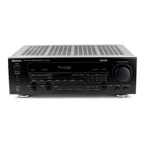
Kenwood KR-A5050 User manual

Kenwood

Kenwood KR-A5050 User manual

Kenwood VR-707A User manual

Kenwood

Kenwood VR-707A User manual

Kenwood KRF-X9992D User manual

Kenwood

Kenwood KRF-X9992D User manual

Kenwood KR-V6080 User manual

Kenwood

Kenwood KR-V6080 User manual

Kenwood KRF-V7771D User manual

Kenwood

Kenwood KRF-V7771D User manual

Kenwood KRF-V4070D User manual

Kenwood

Kenwood KRF-V4070D User manual

Kenwood KR-V9030 User manual

Kenwood

Kenwood KR-V9030 User manual

Kenwood VRS-6100 User manual

Kenwood

Kenwood VRS-6100 User manual

Kenwood KR-A5040 User manual

Kenwood

Kenwood KR-A5040 User manual

Kenwood KRF-V7070D User manual

Kenwood

Kenwood KRF-V7070D User manual

Kenwood 106VR User manual

Kenwood

Kenwood 106VR User manual

Popular Stereo Receiver manuals by other brands

Teac AG-10D Block Diagram

Teac

Teac AG-10D Block Diagram

Philips HTR5205/98 user manual

Philips

Philips HTR5205/98 user manual

WILLAMS SOUND PPA R37-8 user manual

WILLAMS SOUND

WILLAMS SOUND PPA R37-8 user manual

auna multimedia AMP-7100 manual

auna multimedia

auna multimedia AMP-7100 manual

Harman Kardon HK 3370 owner's manual

Harman Kardon

Harman Kardon HK 3370 owner's manual

Denon DRA-395 Service manual

Denon

Denon DRA-395 Service manual

Marantz SR7012 quick start guide

Marantz

Marantz SR7012 quick start guide

Realistic 31-2080 Service manual

Realistic

Realistic 31-2080 Service manual

Denon DRA-800H owner's manual

Denon

Denon DRA-800H owner's manual

Pioneer AVH-Z5190BT owner's manual

Pioneer

Pioneer AVH-Z5190BT owner's manual

Pioneer SX-636 Service manual

Pioneer

Pioneer SX-636 Service manual

Denon AVR-X4200W quick start guide

Denon

Denon AVR-X4200W quick start guide

Denon AVR-1611 Manual Del Usuario

Denon

Denon AVR-1611 Manual Del Usuario

Audioplex STEALTH-PP installation manual

Audioplex

Audioplex STEALTH-PP installation manual

Alpine HALO 9 owner's manual

Alpine

Alpine HALO 9 owner's manual

Pioneer AVH-P4150DVD Operation manual

Pioneer

Pioneer AVH-P4150DVD Operation manual

Yamaha RX-460 Service manual

Yamaha

Yamaha RX-460 Service manual

Marantz 4230 Handbook of instructions

Marantz

Marantz 4230 Handbook of instructions

manuals.online logo
manuals.online logoBrands
  • About & Mission
  • Contact us
  • Privacy Policy
  • Terms and Conditions

Copyright 2025 Manuals.Online. All Rights Reserved.