RXD-M33V
5
CIRCUIT DESCRIPTION
Frequency
P.CH M,M2,I Type K2(M,M2 Type)
1 FM 98.30MHz FM 98.30MHz
2 FM 98.00MHz FM 87.50MHz
3 FM 87.50MHz FM 89.10MHz
4 FM 89.10MHz FM 108.0MHz
5 FM 108.0MHz FM 90.00MHz
6 FM 90.00MHz FM 87.50MHz
7 FM 87.50MHz FM 87.50MHz
8 FM 87.50MHz FM 87.50MHz
9 AM 1602kHz AM 1610kHz
10 AM 999kHz AM 1000kHz
11 AM 630kHz AM 630kHz
12 AM 1440kHz AM 1440kHz
13 FM 106.0MHz FM 106.0MHz
14 AM 531kHz AM 530kHz
15 FM 87.50MHz FM 87.50MHz
16 FM 98.00MHz FM 98.00MHz
17 FM 98.50MHz FM 98.50MHz
18 FM 87.50MHz FM 87.50MHz
19 AM 990kHz AM 990kHz
20 FM 97.70MHz FM 97.40MHz
1. Initializing
1-1 Initialization Method
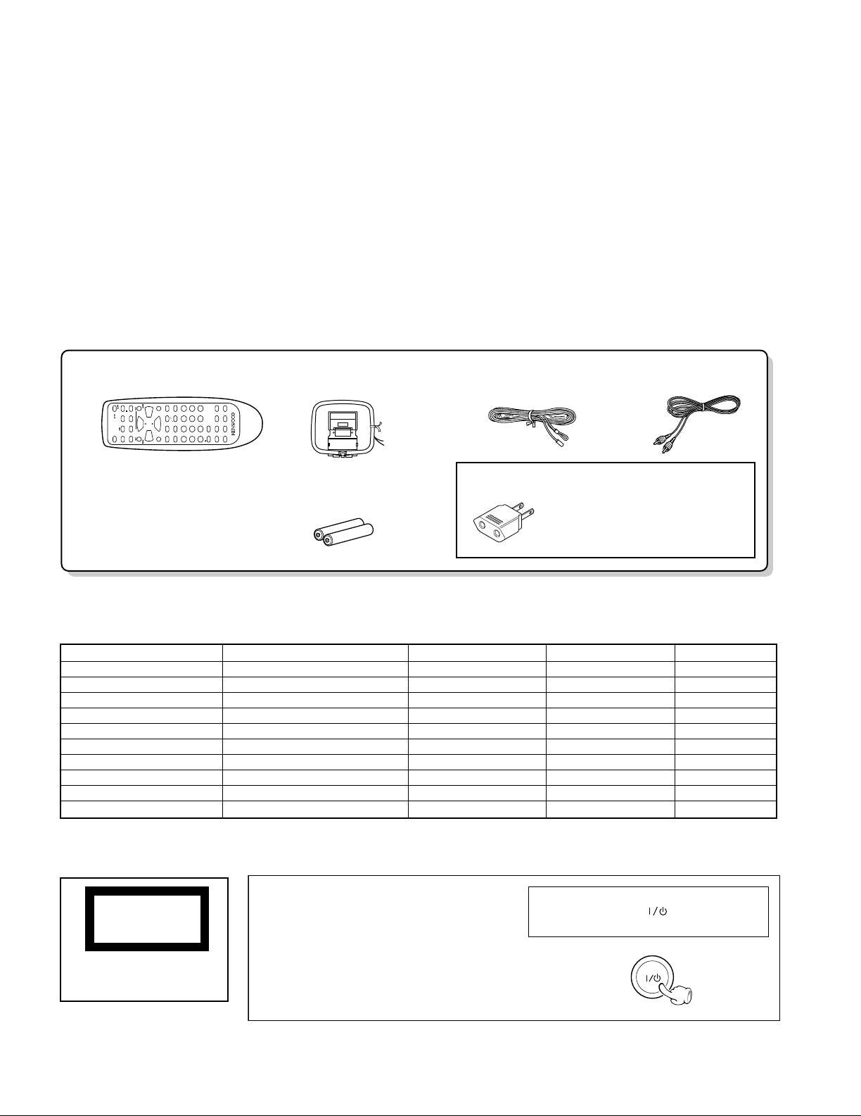
• While pressing the [POWER] key, turn the AC on.
1-2 Initialization Operation
• During the initial operation, the display shows "INI-
TIALIZE" and after that it will be returned to standby
condition.
• If any mechanisms error occurred, the error indication
is displayed as "ERR" in the display.
1-3 Mechanism Initializations
1CD Mechanism
• If a mechanism error occurred, the error indication is
displayed as "C ERR" in the display.
2Deck Mechanism
• If a mechanism error occurred, the error indication is
displayed as "X ERR" in the display.
2. Tuner Destination
Set Destin- Band Receiving Frequency Channel IF RF
ation Range Space
M K2 FM 87.5MHz~108.0MHz 100kHz +10.7MHz 25kHz
AM 530kHz~1610kHz 10kHz +450kHz 10kHz
3. Tuner Preset Frequency
Frequency
P.CH M,M2,I Type K2(M,M2 Type)
21 AM 531kHz AM 530kHz
22 FM 87.50MHz FM 87.50MHz
23 FM 87.50MHz FM 87.50MHz
24 FM 87.50MHz FM 87.50MHz
25 FM 87.50MHz FM 87.50MHz
26 FM 87.50MHz FM 87.50MHz
27 FM 87.50MHz FM 87.50MHz
28 FM 87.50MHz FM 87.50MHz
29 FM 87.50MHz FM 87.50MHz
30 FM 106.0MHz FM 106.0MHz
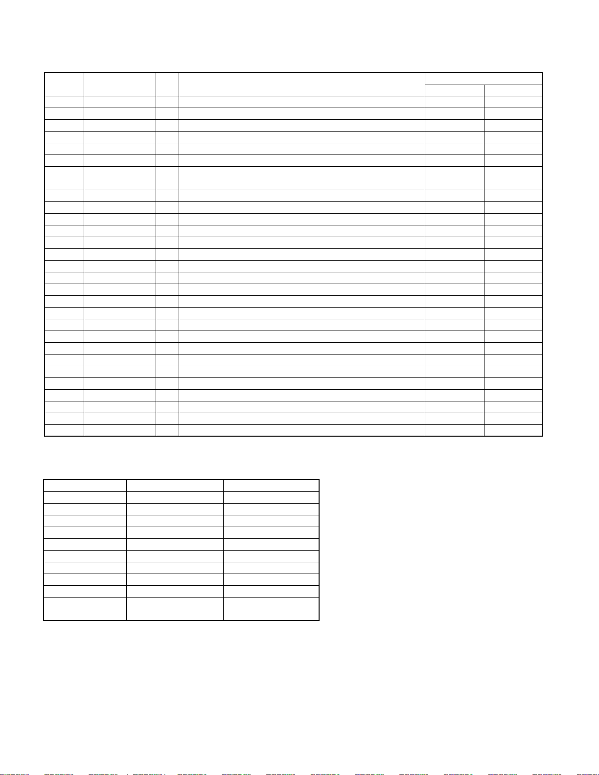
4. Test Mode
4-1 Setting method of the Test Mode
• While pressing the "below each" key in the table, turn
the power switch on.
TEST MODE SETTING METHOD
CD MODE CD PLAY key+AC ON
DECK MODE TAPE PLAY key (3) +AC ON
✽ FCT & SUB CLOCK MENU key + AC ON
OSC DIAGNOSIS
✽ The oscillation diagnosis (existence of oscillation and
measurement of period) of a sub clock is performed
before the test mode is entered. If the diagnosis
result is OK, the system enters the test mode.
If the diagnosis result is NG, the oscillation of the sub
clock is diagnosed again. If the result is OK, the sys-
tem enters the test mode. If the diagnosis result is
continuously NG 5 times, the system stops with
"ERR1" and "ERR2" displayed.
4-2 Cancel of the test mode
• By turning the AC off, the system is initialized and
the test mode is canceled.
• Cancel the test mode only if the power switch is
turned off.
4-3 Contents of the Test Mode
• The muting during mode selection is not controlled
in the test mode.
• During the test mode, it can be operated in a special
manner that is different from an ordinary operation
by using the keys on the main body, specifically as
shown in the following tables.