3
HCD-GX90D/RV800D
This appliance is classified as a CLASS 1 LASER product. The
CLASS 1 LASER PRODUCT MARKING is located on the rear
exterior.
Laser component in this product is capable
of emitting radiation exceeding the limit for
Class 1.
CAUTION
Use of controls or adjustments or performance of procedures
other than those specified herein may result in hazardous radiation
exposure.
Notes on chip component replacement
•Never reuse a disconnected chip component.
•Notice that the minus side of a tantalum capacitor may be
damaged by heat.
Flexible Circuit Board Repairing
•Keep the temperature of soldering iron around 270˚C
during repairing.
•Do not touch the soldering iron on the same conductor of the
circuit board (within 3 times).
•Be careful not to apply force on the conductor when soldering
or unsoldering.
NOTES ON HANDLING THE OPTICAL PICK-UP
BLOCK OR BASE UNIT
The laser diode in the optical pick-up block may suffer electrostatic
break-down because of the potential difference generated by the
charged electrostatic load, etc. on clothing and the human body.
During repair, pay attention to electrostatic break-down and also
use the procedure in the printed matter which is included in the
repair parts.
The flexible board is easily damaged and should be handled with
care.
NOTES ON LASER DIODE EMISSION CHECK
The laser beam on this model is concentrated so as to be focused on
the disc reflective surface by the objective lens in the optical pick-
up block. Therefore, when checking the laser diode emission,
observe from more than 30 cm away from the objective lens.
ATTENTION AU COMPOSANT AYANT RAPPORT
À LA SÉCURITÉ!
LES COMPOSANTS IDENTIFÉS PAR UNE MARQUE 0SUR LES
DIAGRAMMES SCHÉMATIQUES ET LA LISTE DES PIÈCES SONT
CRITIQUES POUR LA SÉCURITÉ DE FONCTIONNEMENT. NE
REMPLACER CES COMPOSANTS QUE PAR DES PIÈSES SONY
DONT LES NUMÉROS SONT DONNÉS DANS CE MANUEL OU
DANS LES SUPPÉMENTS PUBLIÉS PAR SONY.
SAFETY-RELATED COMPONENT WARNING!!
COMPONENTS IDENTIFIED BY MARK 0OR DOTTED LINEWITH
MARK 0ON THE SCHEMATIC DIAGRAMS AND INTHE PARTS
LIST ARE CRITICAL TO SAFE OPERATION. REPLACE THESE
COMPONENTS WITH SONY PARTS WHOSE PART NUMBERS
APPEAR AS SHOWN IN THIS MANUAL OR IN SUPPLEMENTS
PUBLISHED BY SONY.
TABLE OF CONTENTS
1. GENERAL ·········································································· 4
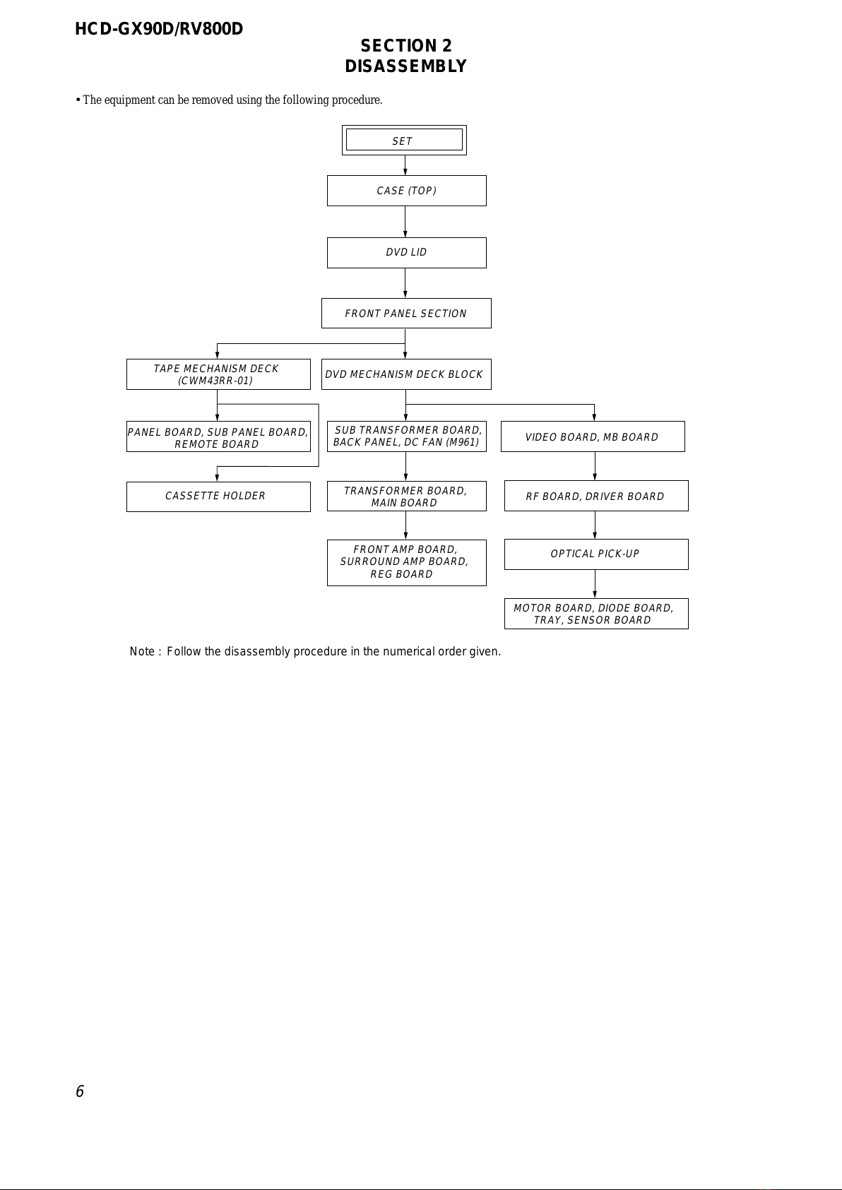
2. DISASSEMBLY ································································ 6
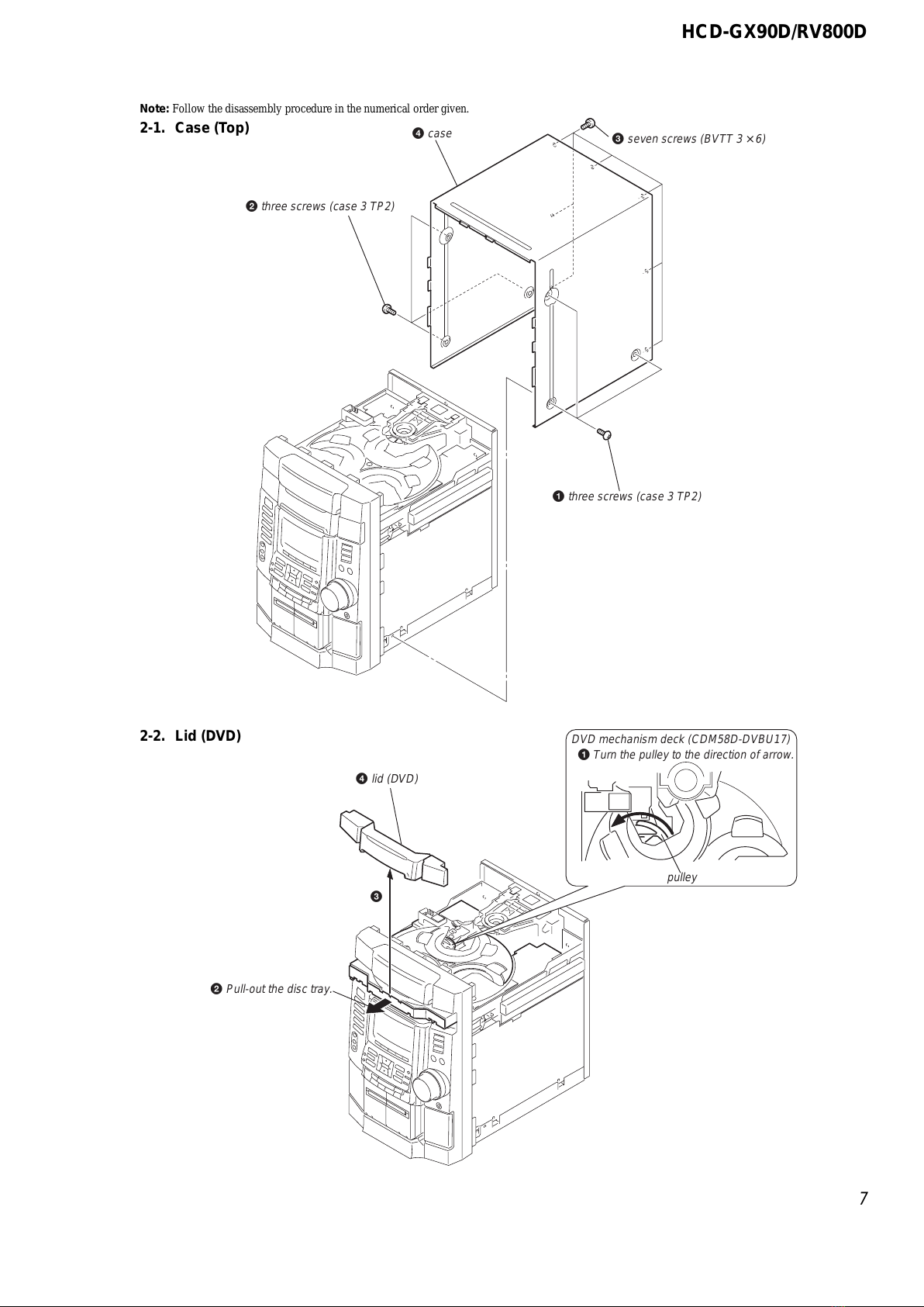
2-1. Case (Top) ····································································· 7
2-2. Lid (DVD)····································································· 7
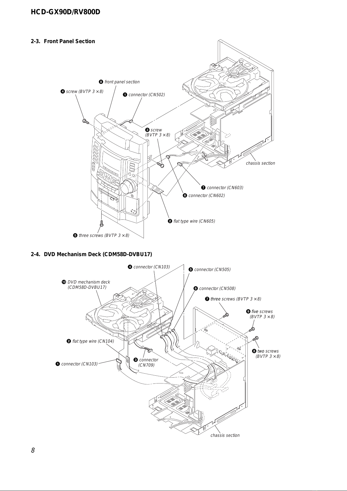
2-3. Front Panel Section ······················································· 8
2-4. DVD Mechanism Deck (CDM58D-DVBU17)············· 8
2-5. Tape Mechanical Deck (CWM43RR-01) ····················· 9
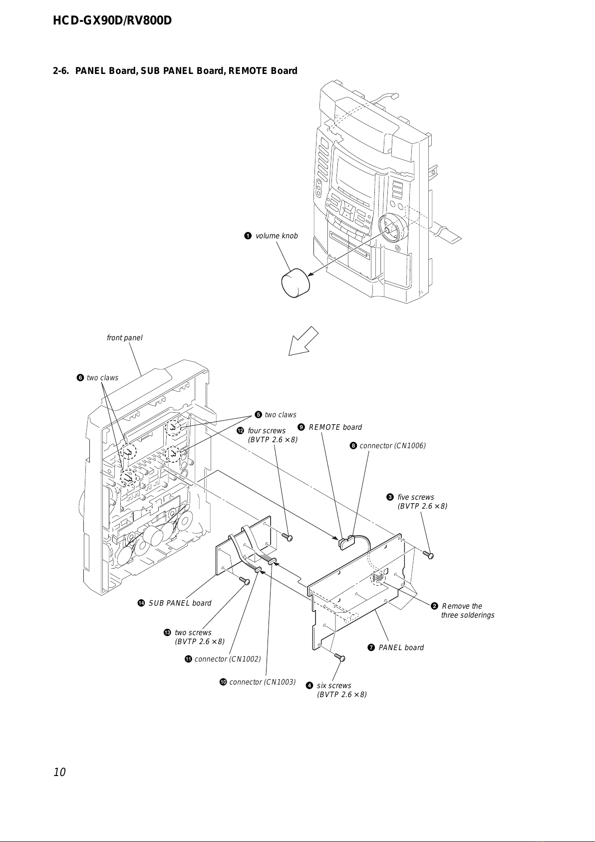
2-6. PANEL Board, SUB PANEL Board,
REMOTE Board ························································· 10
2-7. Cassette Holder ··························································· 11
2-8. SUB TRANSFORMER Board, Back Panel,
DC Fan (M961)··························································· 11
2-9. TRANSFORMER Board, MAIN Board····················· 12
2-10. FRONT AMP Board, SURROUND Board,
REG Board·································································· 12
2-11. VIDEO Board, MB Board ·········································· 13
2-12. RF Board, DRIVER Board ········································· 13
2-13. Optical Pick-up ··························································· 14
2-14. MOTOR Board, DIODE Board, SENSOR Board ······ 14
3. TEST MODE···································································· 15
4. MECHANICAL ADJUSTMENTS ····························· 18
5. ELECTRICAL ADJUSTMENTS ······························· 19
6. DIAGRAMS······································································ 21
6-1. Block Diagrams – DVD DSP Section – ···················· 21
– DVD SYS Section – ···················· 22
– Tuner Section – ···························· 23
– Main Section –····························· 24
6-2. Circuit Boards Location ·············································· 25
6-3. Printed Wiring Board – RF Board – ··························· 26
6-4. Schematic Diagram – RF Board – ······························ 27
6-5. Printed Wiring Board – MB Board (Side A) – ··········· 28
6-6. Printed Wiring Board – MB Board (Side B) – ··········· 29
6-7. Schematic Diagram – MB Board (1/6) – ···················· 30
6-8. Schematic Diagram – MB Board (2/6) – ···················· 31
6-9. Schematic Diagram – MB Board (3/6) – ···················· 32
6-10. Schematic Diagram – MB Board (4/6) – ···················· 33
6-11. Schematic Diagram – MB Board (5/6) – ···················· 34
6-12. Schematic Diagram – MB Board (6/6) – ···················· 35
6-13. Printed Wiring Board – TC Board – ··························· 36
6-14. Schematic Diagram – TC Board – ······························ 37
6-15. Printed Wiring Board – Main Section – ····················· 38
6-16. Schematic Diagram – Main Section (1/3) – ··············· 39
6-17. Schematic Diagram – Main Section (2/3) – ··············· 40
6-18. Schematic Diagram – Main Section (3/3) – ··············· 41
6-19. Printed Wiring Board – VIDEO Board – ···················· 42
6-20. Schematic Diagram – VIDEO Board – ······················· 43
6-21. Printed Wiring Board – FRONT AMP Board – ·········· 44
6-22. Schematic Diagram – FRONT AMP Board – ············ 45
6-23. Printed Wiring Board – SURROUND Board – ·········· 46
6-24. Schematic Diagram – SURROUND Board – ············· 47
6-25. Printed Wiring Board – Panel Section – ····················· 48
6-26. Schematic Diagram – Panel Section (1/2) – ··············· 49
6-27. Schematic Diagram – Panel Section (2/2) – ··············· 50
6-28. Schematic Diagram – Sensor Section – ······················ 51
6-29. Printed Wiring Board – Sensor Section – ··················· 51
6-30. Printed Wiring Board – TRANSFORMER Board –··· 52
6-31. Schematic Diagram – TRANSFORMER Board – ····· 53
6-32. Printed Wiring Board
– SUB TRANSFORMER Board – ····························· 54
6-33. Schematic Diagram
– SUB TRANSFORMER Board – ····························· 55
6-34. IC Pin Function Descriptions······································ 56
7. EXPLODED VIEWS ······················································ 67
7-1. Main Section ······························································· 67
7-2. Front Panel Section ····················································· 68
7-3. Chassis Section ··························································· 69
7-4. DVD Mechanism Deck Section
(CDM58D-DVBU17) ················································· 70
8. ELECTRICAL PARTS LIST······································· 71