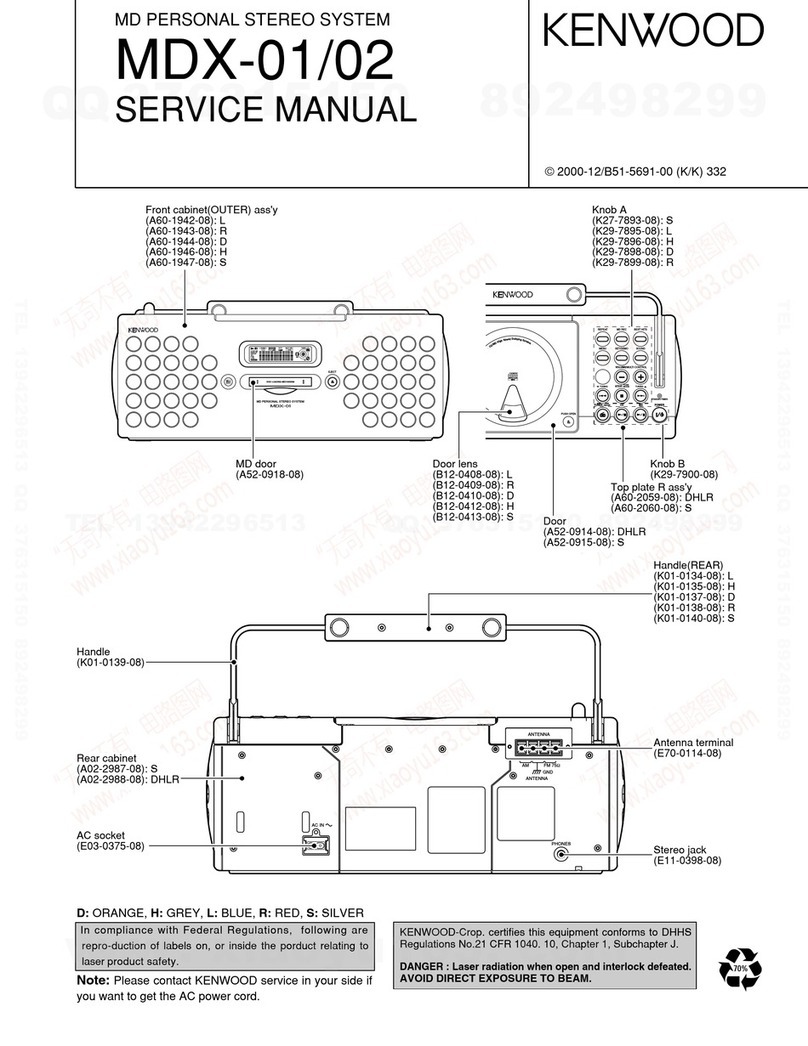
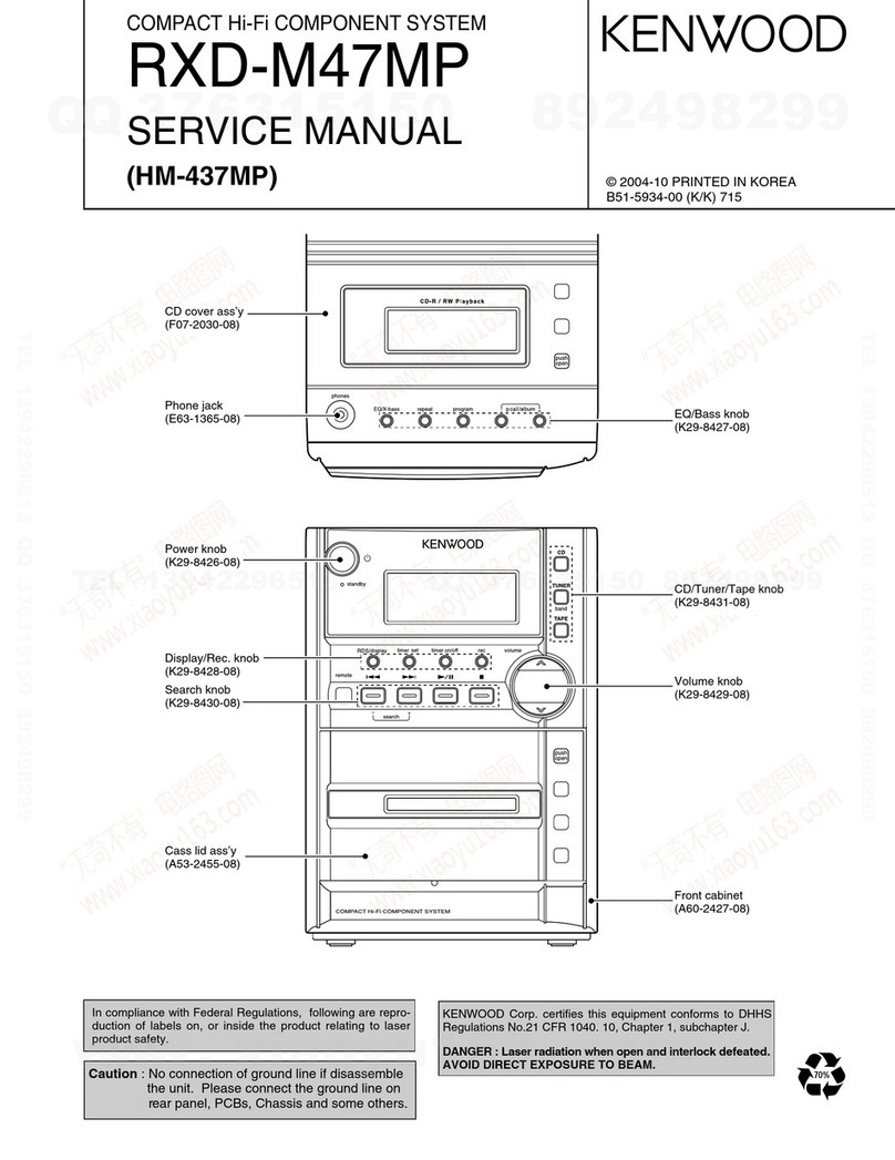
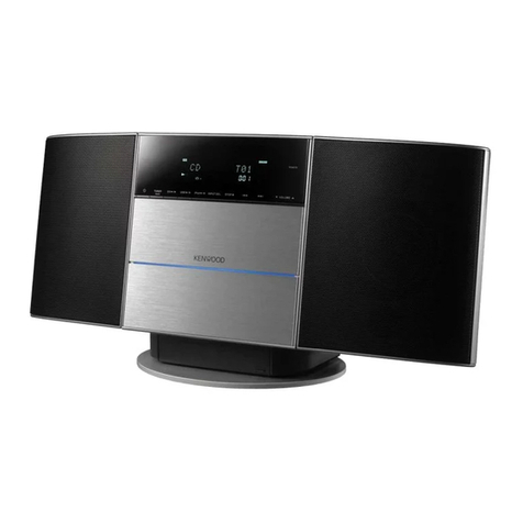
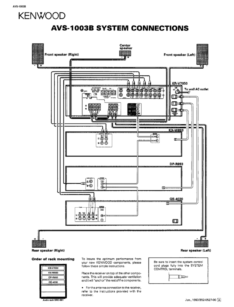
Kenwood MDX-F1 User manual

70%
MD PERSONAL STEREO SYSTEM
MDX-F1
SERVICE MANUAL
P
U
S
H
O
P
E
N
0
FM 75AM GND
AC IN
ANTENNA
In compliance with Federal Regulations, following are
reproductions of labels on, or inside the product relating to
laser product safety.
* Refer to parts list on page 40 .
KENWOOD-Crop. certifies this equipment conforms to
DHHS Regulations No.21 CFR 1040. 10, Chapter 1, Sub-
chapter J.
DANGER : Laser radiation when open and interlock
defeated.
AVOID DIRECT EXPOSURE TO BEAM.
Front glass
(B10-3540-04) Knob ass'y
(K29-7753-04) : S
(K29-7755-04) : R
Panel ass'y
(A60-1729-02) : S
(A60-1803-02) : R Knob
(K29-7669-02) Front glass
(B10-3541-03) Knob
(K29-7669-02)
Knob
(K29-7718-03) : S
(K29-7750-03) : R
Cassette holder
(A53-2174-02) : S
(A53-2188-02) : R
Rod antenna
(T90-0828-05)
Plastic cabinet
(A02-2949-01) : S
(A02-2950-01) : R
Lock terminal board
(E70-0051-05)
Miniature phone jack
(E11-0399-05)
Panel
(A29-1078-04)
S : silver
R : red
Note: Please contact KENWOOD service in your side if
you want to get the AC power cord.

Loop antenna (1)
(T90-0852-05) Remote control unit (1)
(A70-1325-05): RC-MDX0101
Battery cover (A09-1151-08)
R6/SUM-3 batteries
for remote (2) AC plug adaptor (1)
(E03-0115-05)
MDX-F1
2
CONTENTS / ACCESSORIES / CAUTIONS
CONTENTS / ACCESSORIES / CAUTIONS............. 2
CONTROLS................................................................3
DISASSEMBLY FOR REPAIR....................................4
CIRCUIT DESCRIPTION............................................5
ADJUSTMENT..........................................................16
PC BOARD .............................................................. 20
SCHEMATIC DIAGRAM.......................................... 26
EXPLODED VIEW ....................................................38
PARTS LIST..............................................................40
SPECIFICATIONS ......................................Back cover
Contents
Accessories
Cautions
Stored contents which are
cleared immediately when
power plug is unplugged
from power outlet
Stored contents which are
cleared in at least a day
after power plug is
unplugged from power
outlet
Clock display
MD recorder section
Amplifier section
"on/standby" status
(ON or STANDBY)
Input selection
Volume control value
Tone control levels
Tuner section
Receiving band
Frequency
Preset stations
Auto tuning setting
Cassette deck unit
Transport direction
DOLBY NR
Reverse mode
Timer setting contents
Memory backup function
Note related to transportation and movement
Before transporting or moving this unit, carry out the f
ollowing operations.
1Remove the CD or MD from the unit.
2Press the 6key of the MD.
3Wait for some time and verifythat the display
becomes as shown in the figure.
4Press the 6key of the CD.
5Wait for some time and verifythat the display
becomes as shown in the figure.
6Wait a few seconds and turn the unit OFF.
MD NO DISC
CD NO DISC
Operation to reset
The microcomputer may fall into malfunction (impossibility
to operate, erroneous display, etc.) when the power cord
is unplugged while unit is ON or due to an external factor.
In this case, execute the following procedure to reset the
microcomputer and return it to normal condition.
Unplug the power cord from the power outlet then,
while holding the REPEAT key depressed, plug the
power cord again.
÷ Please note that resetting the microcomputer clears
the contents stored in and it returns to condition
when it left the factory.
0
REPEAT
ActionMeaningDisplayed Message
÷ No disc is placed on thetray.
÷ An attempt is made to record digital
signal froma source whileitsdigital copy
has been prohibited by SCMS.
÷ There is no recordable area on the disc.
÷ An attemptis made to record a 256th
track.
÷ An attemptis made to assign a titlewith
more characters than usable.
÷ The disc does not contain any record-
ings.
÷ The disc does not contain any tracks but
has a disc title.
÷ The TOC *1data of the disc is being
read.
÷ The data related to editingor recording is
being writtenin the disc.
÷ The contentsofUTOC*2are abnormal.
÷ An attemptis made to performediting
beyond the restrictions, for example to
erase a track whichis too short.
÷ This is a message forconfirmingif edit-
ing can really be executed.
÷ The minidisc is write-protected.
÷ The minidisc is only for playback.
÷ This indicates some trouble.
÷ Load a disc.
÷ Recording is not possible.
÷ Use another recordable disc.
÷ Morethan 256 tracks cannot berecorded
per disc.
÷ Refer to“Total number of title characters”.
÷ When playback is required, use a recorded
disc.
÷ The disc can be used for recording without
any problem.
÷ This is a normal operation.
÷ Perform “ALLERASE” operation. Ifthis
is not possible, use another disc.
÷ Perform editing followingthe restrictions.
÷ Press theENTER key toexecute editing.
÷ Cancel the write protection.
÷ Insert a minidisc for recording.
÷ Return to normal condition is made by
switching the unit off and then on again.
NO DISC
CAN'T COPY
DISC FULL
TITLE FULL
BLANK DISC
NO TRACKS
READING
WRITING
DISC ERROR
CAN'T EDIT
?(blinking)
PROTECTED
PLAY ONLY
UNIT ERROR
MD recorder section (Displayed messages and actions to be taken against them)
*1All minidiscs contain a Table of Contents (TOC) in addition to sound signals. The TOC is similar to the table of contents
in a book and contains information,such as track numbers, track length, and character information,that cannot be
rewritten.
*2In addition to theTOC, minidiscs also contain a special User’s Table of Contents(UTOC) that contains track number, track
length, and character information,that can be rewritten.
Memory Backup for the MD Recorder Section
The contents of the memory are not stored on the disc if the power cord is unplugged.
If the power cord is unplugged suddenly or there is a power failure, the information on recording and editing
(normally recorded when the minidisc is ejected) may be erased or destroyed before it is recorded on the
minidisc. Once the information has disappeared, it can not be recovered.
After recording or editing, always remove the minidisc to record the recording or editing information.

MDX-F1
3
CONTROLS
Display
(The displays given in this manual are approximations only.
They may differ from what actually appears on the display.)
1PGM (program) indication
2Indication related to CD and MD
3Timer-related indicators
4A.P.S. (Auto Power Save) indicator
5Character information display section (dot display)
Shows character information including the input selection,
volume level and disc/track title
6Character information display section
Frequency indication, time indication, track No., program
No., etc.
7Tuner-related indicators
8TAPE EQ. indication
9O.T.E. (ONETOUCH EDIT) indication
Appears during one-touch recording.
0Selector-related indicators
!TITLE SEARCH indication
@MD EDIT indication
#LOUD (Loudness) indication
$EX.BASS (extra bass) indication
•
•
•
•
•
•
•
•
•
•
•
TITLE SEARCH
MHz
kHz O.T.E.
TAPE EQ.
STEREO
TUNEDAUTOTOTAL
3
ALL
3
REPEAT
3
RANDOM

SLEEP
TRACK NO.
PM
A
M
FM
88888888
MD EDIT
1 2
LOUD
EX BASS
A.P.S.

O.T.T. PROG.
REC
REC
PGM
5!
6 @ # $7
2 41 033
98
Cassette holder
(POWER) key
“STANDBY/TIMER” indicator
Remote sensor
Display
() STOP key (CD/MD/TAPE/TUNING MODE)
key (CD/MD/TAPE/tuner tuning)
“SOUND” key
“MENU” key
“REPEAT” key
“TUNER FM/AM” key
“CD ” key
“MD ” key
“TAPE ” key
PUSH OPEN button
“TAPE REC” key
“MD REC” key
“VOLUME/MULTI CONTROL” knob
Mini Disc insertion slot
EJECT ( ) key
“SET/Demo” key
About the one-touch operation function
This unit incorporates the one-touch operation function for the user's convenience.
With this function, pressing any key enclosed in ( ~ ) while the unit is in standby mode immediately start
playback (or reception).
PUSH OPEN button
Top panel
Main unit
Front panel

MDX-F1
4
DISASSEMBLY FOR REPAIR
2
2
11
1
1
3
3
x3
x2
x1
3x1
x1 x1 x1
x1
x3
2x3
FIG.1
BOTTOM
FRONT PANEL BOTTOM
4
4
44
FIG.2
5
5
5
5
5
5
FIG.3
1 Remove 3 screws from bottom side(1X3).
2 Remove 8 screws on rear panel(2X8).
3 Remove 3 screws on rod ant(3X3).
4 Lift rear side of top cover and remove it.
Insert the screw driver to contact of door ass'y and sub
panel if remove door ass'y.
How to Disassemble Front Panel and Rear
Panel
How to Remove Door Ass'y
5 Remove 4 screws(4X4).
6 Lift and slide CD parts of top cover by using handle
7 Remove 6 long screws(5X6), slide front panel front-
wards.

MDX-F1
5
CIRCUIT DESCRIPTION
1. Initialization
1-1 Setting
Insert the AC power cord with pressing the REPEAT key.
1-2 Operation
Display shows "INITIALIZE" if the unit works in initializa-
tion mode. It shows "STANDBY" after the unit is end of
work.
The unit is shipment condition(MD disc comes out, RAM
is clear, Backup data is also.) if normal mechanisms are
initialization.
Display shows error message as follows if the every
mechanism has an initialization error and CD door switch
malfunction. Error
CD The first digit: C
MD The third digit: M
CASSETTE The 5th digit: X
CD DOOR SW The 7th digit: S
2. TUNER Preset 3. TUNER SPECIFICATIONS
P.CH BAND FREQ P.CH BAND FREQ
1 FM 83.50MHz 6 FM 90.00MHz
2 FM 76.00MHz 7 FM 76.00MHz
3 FM 89.10MHz 8 AM 1629kHz
4 FM 108.00MHz 9 AM 1602kHz
5 FM 91.50MHz 10 AM 999kHz
P.CH BAND FREQ P.CH BAND FREQ
11 AM 630kHz 26 FM 76.00MHz
12 AM 1440kHz 27 FM 76.00MHz
13 FM 106.00MHz 28 FM 76.00MHz
14 AM 531kHz 29 FM 97.50MHz
15 FM 76.00MHz 30 FM 106.00MHz
16 FM 91.50MHz 31 FM 76.00MHz
17 FM 92.50MHz 32 FM 76.00MHz
18 FM 76.00MHz 33 FM 76.00MHz
19 AM 990kHz 34 FM 76.00MHz
20 FM 91.40MHz 35 FM 76.00MHz
21 AM 531kHz 36 FM 76.00MHz
22 FM 76.00MHz 37 FM 76.00MHz
23 FM 76.00MHz 38 FM 76.00MHz
24 FM 76.00MHz 39 FM 108.00MHz
25 FM 76.00MHz 40 AM 945kHz
BAND RECEIVING CHANNEL IF PLL
FREQ. SPACE
FM 76.0MHz~87.5MHz 100kHz -10.7MHz 25kHz
FM 87.5MHz~108MHz 50kHz -10.7MHz 25kHz
AM 531kHz~1629kHz 9kHz +450kHz 9kHz
ACTIVE
Port # Port Name I/O Descriptions HL
1 DSTP O CD disc motor servo control output port OFF ON
2 XLON O Bias control port ON OFF
3 LDC O LD control OFF ON
4 SCLK O CD sense data read clock
5 SENSE I CD sense input 1 0
6 CD CLK O Clock for CD DSP
7 XLAT O CD DSP latch output
8 BYTE I GND
9 CNVSS I GND
10 XCIN I Timer clock(32.768kHz)
11 XCOUT O Timer clock(32.768kHz)
12 RESET I Microprocessor reset signal input NORMAL RESET
13 XOUT O Main clock port
14 VSS - GND
15 XIN I Main clock port (10MHz)
16 VCC(B.U.) - Power supply port (+5V)
17 NMI I +5.0V
18 REMOCON I Remote control signal input port
19 NC O open
20 SCOR I Sub-code synchro signal port
21 XRST O CD DSP reset signal output port NORMAL RESET
22 PLL DO I PLL data input port
23 SA CE O PLL IC chip enable
24 SA CLK O PLL IC clock
25 SA DATA O PLL IC data output port
26 ST I Stereo sensor port for tuner MONO STEREO
27 SD I SD sensor port for tuner UNTUNED TUNED
28 SQCK O Sub-code clock for CD
29 SQSO I Sub-code input port for CD
30 NC O open
4. MAIN MICROPROCESSOR: M30622MC-746(X09,IC601)
4-1 Port descriptions

MDX-F1
6
CIRCUIT DESCRIPTION
ACTIVE
Port # Port Name I/O Descriptions HL
31 FL DATA O Output port for FL driver
32 NC O open
33 FL CLK O Clock output port for FL driver
34 CD DOOR SW2 I CD DOOR OPEN sensor switch ON
35 K DATA O Data transmission port to MD(UART)
36 MD DATA I Data input port from MD(UART)
37 DSCK O MD IC clock
38 CD DATA O CD DSP data output port
39 DSTB O MD STB output port
40 SDA(EPROM) - open
41 SCL(EPROM) - open
42 MD RST O Reset signal port for MD RESET NORMAL
43 PDOWN O MD POWER ON OFF
44 MD ST O MD ON/CD SYNC
45 SEARCH O MD SEARCH output port
46 LOAD SW I MD LOADING sensor switch input port OFF ON
47 CD DOOR SW1 I CD DOOR sensor switch port OFF ON
48 RDS DATA - GND
49 MD NOT - GND
50 F1/MICRO - GND
51~56 NC - open
57~59 DSW0~DSW2 - GND
60 DSW3 I Destinations selector J TYPE M TYPE
61 VOL CLK O System IC
62 VCC(B.U.) - Power supply port (+5V)
63 A120/70 O Playback EQ selector
64 AVSS - GND
65 A/B-2 O Cassette deck operation mode selector
66 A/B-1 O Cassette deck operation mode selector
67 BT/2 O Cassette deck operation mode selector
68 REC/PLAY O Cassette deck rec/play mode selector REC PLAY
69 BEAT CANCEL O Beat cancel control port ON OFF
70 BIAS O Bias control port ON OFF
71 CPM O Cassette deck motor control port ON OFF
72 SOL O Cassette deck solenoid control port ON OFF
73 PLAY SW I Cassette deck play switch control port OFF ON
74 CrO2 SW I CrO2 tape detection CrO2 NORMAL
75 PACK SW I Cassette half switch control port OFF ON
76 REC F I Cassette deck forward rec switch control port OFF ON
77 REC R I Cassette deck revise rec switch control port OFF ON
78 VOL DATA O System IC data port
79 A MUTE O Audio mute control port OFF ON
80 STBY O STANDBY control port
81 NC O open
82 POWER O MAIN POWER control port OFF ON
83 FL RST O Reset signal output port for display NORMAL RESET
84 FL CE O Chip enable signal output port for display
85 ENC1 I Rotary encoder input1 port
86 ENC2 I Rotary encoder input2 port
87 LEDR O LED(STANDBY,RED) control port ON OFF
88 LEDG O LED(TIMER,GRN) control port ON OFF
89 PHOTO I Cassette deck turning detection
90,91 KEY2,KEY1 I Key a/d converter input port
92 NC O open
93 ADP3 I Protection signal I/o port 3(ON: less0.5V)
94 ADP1 I Protection signal I/o port 1(ON: less0.5V)
95 ADP2 I Protection signal I/o port 2(ON: less0.5V)
96 AVSS - GND(A/D)
97 CE I BACK UP detection port
98 VREF - A/D converter standard voltage (+5V)
99 VCC(B.U.) - A/D converter power supply(+5V)
100 CD POWER O CD DSP power supply control ON OFF

MDX-F1
7
CIRCUIT DESCRIPTION
5. Voltage Key Matrix
(port # of IC601)
Voltage of Key 0~0.35V 0.5~0.9V 1.0~1.5V 1.6~2.1V 2.2~2.8V 2.9~3.4V 3.5~4.0V 4.1~4.6V 4.8~5.0V
KEY1(#91) SOUND REPEAT MENU SET MD EJECT MD REC - TAPE REC OFF
KEY2(#90) POWER STOP MD CD TUNER TAPE SKIP UP SKIP OFF
PLAY/PAUSE PLAY/PAUSE FM/AM PLAY DOWN
Port # Port Name I/O Description
1 4M/16M I GND
2 64M I GND
3 LDVAR O Laser power adjust port
4 ADJS O Check port
5 CIN I Track count port
6 NC - No use
7 UNLOCK I GND
8 BYTE I GND
9 CNVSS I GND
10 STID OUT O ST-ID output port
11 SEACH OUT O MD research port
12 RESET I Reset signal input port
13 NC - No use
14 VSS - GND
15 MCCK I 8.4672MHz
16 VCC I +3.2v
17 NC I Connection to H level
18 DINT I Interrupt signal from MD LSI
19 SFSY I Frame synchro
20 ST-ID I ST-ID IN/MD ON/re-power after power breakdown
21 SERCH I CD search input port
22 MDR SW O Save control motor drive
23 CDB SEL O CD BLK SEL output port
24 DSENSE I Servo SENSE signal form MD LSI input port
25 PDOWN I Power down detection port
26 HDON O Current control of record head
27 EEPROM O Cancel signal output port to EEP-ROM
28 4.23 O 4.23MHz
29 EEPK O EEP-ROM serial clock port
30 EEPD I/O EEP-ROM data I/o port
31 MDDATA O MD data output port
32 KDATA I System data input port
33 DSCK I System synchro clock input port
34 DSTB O System line busy or to permit usage
35 DATA O R data
36 SBO I Serial data in sub code input port
37 SBCK O System line of serial clock in sub code output port
38 LATCH O R-latch
39 R/P O Rec/play selector
40 FOK I Focus servo monitor port
41 FLASH L I No use
42 CLOCK O R clock
43 SYRS O MD LSI resister selector output port
44 SYRD O MD LSI read signal output port
45 SYWR O MD LSI wright signal output port
46 FLASH H I No use
47-54 SYSD(7-0) I/O MD LSI data bus(0-7)
55-59 SLOT(1-5) I No use
60 NC O No use
61 CRTRO SW I GND
62 VCC I +3.2V
63 INNER I Pickup start position detection port
64 GND - GND
65 L3DATA O AD/DA serial data output port
66 L3MODE O AD/DA serial mode output port
67 L3CLK O AD/DA serial clock output port
6. MD System Microprocessor:IX0342AW(IC1401)

MDX-F1
8
CIRCUIT DESCRIPTION
Port # Port Name I/O Description
68,69 NC O No use
70 PCNTO O Power control output port
71 EJECT O No use
72 LDON O Laser diode on signal port(H:ON)
73 A/B I AD/DA converter selector (in or out)
74 SBSY I Synchro signal input port
75 DAPON O No use
76 DFSO O No use
77 DFSI O No use
78 5/3 I GND
79 C/N I GND
80 XRST O MD LSI reset signal port
81 ADMUTE O AD muting port
82 LD+ O Loading motor positive control port
83 LD- O Loading motor negative control port
84 MUTE O Muting signal output port
85 DOUT MT O No use
86-88 TEST(2-0) I No use
89 AVCK3 I Power supply monitor of motor driver
90 AVCK2 I Power supply monitor of AD/DC converters
91 AVCK1 I Power supply monitor of head circuit
92 DTEMP I Temperature monitor port
93 MINF I Disc, rec window,mechanism position
94,95 TEST(K1-K2) I No use
96 GND - GND
97 NC O No use
98 VREF I +3.2V
99 AVCC I +3.2V
100 PR I GND
** In Tape Mode, 4 seconds recording mode only.
*** FTC & Sub clock Oscillation
a) Check the oscillation(yes or no, period)before FTC test mode.
b) Check is 5 times by 200ms. FTC test mode is carried out if one time is OK.
c) Display shows error message as follows and test mode will be stop.
No oscillation îERR 1 Poor period îERR 2
7-2 Cancel
a. Cancel the test mode and initialize the unit if pull out the power cord from AC outlet.
b. Cancel the test mode only if the power switch is off.
7-3 Operation in Test Mode
a. Muting does not work except power on/off.
b. No display demo mode.
c. Key is different operation from normal mode.
7. Test Mode
7-1 Setting Mode Key Setting Remarks
AUX SOUND
TUNER TUNER
CD CD PLAY Insert the AC power cord with pressing
MD -1 MD PLAY the left key
* TAPE TAPE PLAY **TAPE REC key
*** FTC & sub clock oscillation MENU
MD-2 SET
* Operation & Display in Test Mode
E E E E CrO2 detection L= sw off (-)
Half detection
FWD misrecord detection
RVS misrecord detection
H= sw off (E)

MDX-F1
9
CIRCUIT DESCRIPTION
7-4 Key Operation in Test Mode
7-4-1 Tuner Mode
7-4-2 CD Mode
Key Display Descriptions
STOP Normal mode Select the receiving mode of AUTO(STEREO) or MANUAL(MONO)
SOUND Normal mode Select the preset memory by ten step.
î10î20î30î40î00(--)î
MD REC TUNING DOWN/UP
TAPE REC Normal mode
SKIP DOWN P.CH DOWN/UP
SKIP UP Normal mode
SET/DEMO A MUTE ONîMUTE ON Mute operation works alternately: îAUDI0 MUTE
îMUTE OFFîîMUTE ONîMUTE OFFî
Key Display Descriptions
CD PLAY 05 - - : - - TRACKING-SERVO:ON
03 - - : - - TRACKING-SERVO:OFF
01 - - : - - Stop to operation
07 TB value/ FB value Both TB and FB values
STOP* 08 TG value/ FG value Both TG and FG values
09 FE value/ RF value Both FE and RF values
10 TE value /VC value Both TE and VC values
SKIP UP EX : 01~02 CD's track up operation
MD REC Time CD's FF operation. Feed the pickup outwards at STOP mode
SKIP DOWN EX : 02~01 CD's track down operation
TAPE REC Time CD's FB operation. Feed the pickup inwards at STOP mode.
*Value shows self-adjustment result and hex.
7-4-3 MD Mode
Key Display Descriptions
STOP 01 - - : - - Stop the MD operation. Muting is off.
SOUND DIGITAL In STOP mode, select the input of recording
ANALOG In STOP mode, select the input of recording
SKIP UP EX : 01~02 MD's track up operation
SKIP DOWN EX : 02~01 MD's track down operation
SET ALL ERASE Stop the MD operation. Start operation of ALL-ERASE if disc is recordable.
REPEAT Normal mode One Touch Edit operation starts.

MDX-F1
10
CIRCUIT DESCRIPTION
Repair(replace) Temperature
Standard Set EEPROM set
value check Auto pre adj Auto adj Auto Fab adj *EEPROM data write ** Operation check
TEMP EEPROM_SET AUTO_YOBI AUTO_ADJ AUTO_FAB CANCEL TEST MODE TEST-PLAY TEST-REC
pickup - 1 2 3 4 5 6 7
recording head - - - - - - - 1
mechanism - 1 2 3 4 5 6 7
pcb parts 1 2 3 4 5 6 7 8
MD microprocessor - 1 - - - 2 3 4
MD LSI - - 1 2 3 4 5 6
RF iC 1 2 3 4 5 6 7 8
EEPROM 1 2 3 4 5 6 7 8
1. Preparation for Adjustment(MD-2)
You have to carry out the following test mode items if replace MD mechanism, pickup, head and pc board.
1-1 Procedure
1. Short-circuit #4(vss) and #7(wp) of IC1402(EEPROM).
2. Set the unit to test mode and carry out the every adjustment in test mode.
3. Stop the test mode by pressing the STOP key for 3 secs
4. Remove the short circuit of IC1402. Carry out reset start.
note: figures order of steps. - = no need.
* Result of EEPROM
OK_EEPROM Write the data of setting values and AUTO-pre adjustment perfectly.
WR_EEPROM Write the data of setting values perfectly however not write AUTO pre-adjustment.
Carry out AUTO-pre adjustment and write data to EEPROM.
NG_EEPROM Not write the data of setting values.
Check the connection of MD microprocessor and EEPROM.
** Carry out the TEST-PLAY , TEST-REC and C1 error in test mode after AUTO_ADJ and AUTO_FAB.
7-4-4 MD SECTION
1-2 Test disc
Type Test disc
1 High reflection disc TGYS1 (SONY)
2 Low reflection disc Recording minidisc
3 Head Adjusting transparent
2. Test mode
Test mode setting method
1. Holding down the SET button and turn power on.
(State A )
2. Insert the playback disc 1 (high reflection disc) or recording disc 2 (low reflection disc).
(State B is set.)
(During disc loading : display LOADING)
Thus, the test mode state is set.
A
tsm e: TEST MODE represents version of MD microcomputer.
TEST STOP state (When the (STOP) button is ressed in the A state, the indicationC
is restored. To restore B again, press the MD REC button.)
B AUT
YOBI
C
MD
TEST
Entering the specific mode
Whenever the buttonMD REC is pressed, the mode is changed.
AUTO
(AUT YOBI) (AUTO AJST) (AUT FAB) (RST YOBI) (RESULT)
(MNU YOBI)(EEPROM SET) (MNU AJST)
pre-adjustment AUTO adjustment RESULT SUB RESULT
EEPROM setting MANUAL adjustment MANUAL pre-adjustment
AUT

MDX-F1
11
CIRCUIT DESCRIPTION
• Canceling the test mode
When the POWER button is pressed, the test mode is canceled, and the POWER OFF state is set.
• Test Mode
1. AUTO pre-adjustment mode ¥ Automatic pre-adjustment is performed. (After adjustment the grating adjustment mode is set.)
¥ The adjustment value is output with the aid of system controller interface.
2. AUTO adjustment mode ¥ Automatic adjustment is performed.
¥ The adjustment value is output with the aid of system controller interface.
¥ Continuous playback is performed. (Error rate indication, jump test)
4. RESULT sub-mode ¥ The measurement value, set value and calculated value are indicated.
¥ The set value is changed manually (in servo OFF state).
3. AUTO FOCUS BIAS adjustment ¥ Focus bias adjustment is performed auto matically.
5. RESULT mode (final adjustment) ¥ The set value (after calculation) is indicated.
¥ The set value is changed manually (in servo OFF state).
6. MANUAL pre-adjustment mode ¥ RF side manual adjustment is performed.
¥ Focus and tracking signal ATT manual adjustment is performed.
¥ Focus and tracking signal offset setting is performed.
7. MANUAL adjustment mode ¥ Focus and tracking signal ATT manual adjustment is performed.
8. EEPROM setting mode ¥ EEPROM setting
9. TEST-PLAY mode ¥ Continuous playback from the specified address is performed.
¥ C1 error rate measurement.
10.TEST-REC mode ¥ Continuous recording from the specified address is performed.
¥ Change of record laser output (servo gain is also changed according to laser output)
11. EJECT mode ¥ TEMP setting (of EEPROM setting)
1. AUTO pre-adjustment mode (Low reflection disc only)
Step No. Setting Method Remarks Display
Step 1 Testmode STOP state [tsm e ]
Step 2 Press once the MD REC button. AUTO pre-adjustment menu [ AUT_ YOBI_ _ _ ]
Step 3 Press once the MD PLAY button. The slide moves to the innermost periphery, and automatic [ :_
_
_____]
pre-adjustment is started.
¥ During automatic adjustment changes as follows.
HAo
®
RFg
®
SAg
®
SBg
®
PTG
®
PCH
®
GTG
®
GCH
®
RCG
®
SEG
®
RFG
®
SAG
®
HAO
®
HEO
®
TCO
®
LAO
End of adjustment If adjustment is OK, Step 4.
If adjustment is NG, Step 5.
Step 4 Grating adjustment, [_COMPLETE_]
adjustment value output
Press once the MD STOP button. STEP 2
Step 5 Adjustment value output [ AUT YOBI ]
Press once the MD STOP button. STEP 2 AUTO pre-adjustment menu
¥: Adjustment name, : Address
2. AUTO adjustment mode
Step No. Setting Method Remarks Display
Step 1 Testmode STOP state [tsm e ]
Step 2
Press the ENTER button two times.
AUTO adjustment menu [ A U T O _AJST_]
Step 3 Press once the MD PLAY button. The slide moves to the innermost periphery, and automatic [ :______]
adjustment is started.
¥ In case of high reflection disc changes as follows.
PEG
®
HAG
¥In case of low reflection disc changes as follows.
PEG
®
LAG
®
GCG
®
GEG
®
LAG
End of adjustment If adjustment is OK, Step 4.
If adjustment is NG, Step 7.
Step 4 Adjustment value output [_COMPLETE_]
Press the MD PLAY button. STEP 5
Press the MD STOP button. STEP 2
Step 5
Continuous playback (groove section)
[a c ]
Step 6 Press the MD STOP button. STEP 2 AUTO adjustment menu
Step 7 Adjustment value output [ Can't _ ADJ. ]
Press the MD STOP button. STEP 2 AUTO adjustment menu
¥: Adjustment name, : Measurement value, : Address

MDX-F1
12
CIRCUIT DESCRIPTION
3. AUTO FAB adjusting mode
Step No. Setting Method Remarks Display
Step 1 Test mode STOP state
Step 2 Press the MD REC button three times AUTO FAB adjustment menu [_AUT_FAB_ _]
Step 3 Press the MD PLAY button 1 time
End of automatic adj. step 4
High reflection disc step 5
Step 4 Press the MD STOP button AUTO FAB adjustment menu, step 2
Step 5
Message output for 1 sec. AUTO FAB.
Adjustment menu(high reflection disc)
¥ : measurement value : FAB value in measurement, : C1 error value in measurement, : FAB
value
¥ If the STOP button is pressed while the AUTO FAB adjustment is displayed, the state is change to the TEST mode STOP
state.
¥ If the STOP button is pressed while the automatic adjustment is displayed, the state is change to the AUTO FAB
adjustment state.
Step 1 Test mode STOP state [ t s m e ]
Step 2
Press the MD REC button 4 times.
RESULT sub-menu [ _ R S T _ Y O B I _ ]
Step 3 Press once the MD PLAY button. Indication of measurement value [ R F G : _ _ __ _ ]
Step 4 Press once the MD REC button. Indication of measurement value [ R C G : _ _ __ _ ]
Step 5 Press once the MD REC button. Indication of measurement value [ R T G : _ _ _ _ _ ]
Step 6 Press once the MD REC button. Indication of measurement value [ G T G : _ _ _ _ _ ]
Step 7 Press once the MD REC button. Indication of measurement value [ P C H : _ _ _ _ ]
Step 8 Press once the MD REC button. Indication of measurement value [ G C H : _ _ _ _ ]
Step 9 Press once the MD REC button. Indication of measurement value [ S A G : _ _ _ ]
Step 10 Press once the MD REC button. Indication of measurement value [ S B G : _ _ _ ]
Step 11 Press once the MD REC button. Indication of measurement value [ S E G : _ _ _ ]
Step 12 Press once the MD REC button. Indication of measurement value [ S F G : _ _ _ ]
Step 13 Press once the MD REC button. Indication of measurement value [ H A O : _ _ _]
Step 14 Press once the MD REC button. Indication of measurement value [ H B O : _ _ _]
Step 15 Press once the MD REC button. Indication of measurement value [ H E O : _ _ _]
Step 16 Press once the MD REC button. Indication of measurement value [ H F O : _ _ _]
Step 17 Press once the MD REC button. Indication of measurement value [ L A O : _ _ _]
Step 18 Press once the MD REC button. Indication of measurement value [ L B O : _ _ _]
Step 19 Press once the MD REC button. Indication of measurement value [ L E O : _ _ _]
Step 20 Press once the MD REC button. Indication of measurement value [ L F O : _ _ _]
Step 21 Press once the MD REC button. Indication of measurement value [ T C O : _ _ _ _]
Step 22 Press once the MD REC button. Indication of adjustment error sequence No. [ Y O B : _ _ _ _]
Step 23 Press once the MD REC button. Indication of adjustment status [ D I F : _ _ _ _]
Step 24 Press once the MD REC button. Indication of pre-adjustment not completed (00)/completed (4B) [ A D J : _ _ _ _]
Step 25 Press once the MD STOP button. RESULT sub-menu state [ _ R S T _ Y O B I _ ]
4. RESULT sub-mode
Step No. Setting Method Remarks Display
: Measurement value, : Adjustment value, : Other various informations
When the FF(¡)button in remote controller is pressed while the setting is displayed, the setting increases,
and a new setting is stored in RAM.
When the FB(1)button in remote controller is pressed while the setting is displayed, the setting increases,
and a new setting is stored in RAM.
When the FF or FB button in remote controller is pressed continously, steps is change by 100ms period.

MDX-F1
CIRCUIT DESCRIPTION
13
When the FF(¡)button in remote controller is pressed while the setting is displayed, the setting increases,
and a new setting is stored in RAM.
When the FB(1)button in remote controller is pressed while the setting is displayed, the setting increases,
and a new setting is stored in RAM.
When the FF or FB button in remote controller is pressed continously, steps is change by 100ms period.
Step 1 Test mode STOP state [ t s m e ]
Step 2
Press the MD REC button 5 times.
RESULT menu [ _ R S T U L T _ _ _ ]
Step 3 Press once the MD PLAY button. Indication of set value [ H A G : _ _ _ ]
Step 4 Press once the MD REC button. Indication of set value [ H B G : _ _ _ ]
Step 5 Press once the MD REC button. Indication of set value [ L A G : _ _ _ ]
Step 6 Press once the MD REC button. Indication of set value [ L B G : _ _ _ ]
Step 7 Press once the MD REC button. Indication of set value [ P E G : _ _ _ ]
Step 8 Press once the MD REC button. Indication of set value [ P F G : _ _ _ ]
Step 9 Press once the MD REC button. Indication of set value [ G E G : _ _ _ ]
Step 10 Press once the MD REC button. Indication of set value [ G F G : _ _ _ ]
Step 11 Press once the MD REC button. Indication of set value [ G C G : _ _ _ _ ]
Step 12 Press once the MD STOP button. RESULT menu state [ _ R E S U L T _ _ _ ]
5. RESULT mode (final adjustment)
Step No. Setting Method Remarks Display
: Measurement value
Step 1 Test mode STOP state [ t s m e ]
Step 2
Press the MD REC button 6 times.
MANUAL auxiliary adjustment mode [ _ M N U _ Y O B I _ ]
Step 3 Press once the MD PLAY button. Initial setting Temperature measuring mode [ T M P : _ _ _ _ ]
Step 4 Press once the MD REC button. Offset "0" setting A signal offset tentative measurement [ H A o : _ _ _ ]
Step 5 Press once the MD REC button. B signal offset tentative measurement [ H B o : _ _ _ ]
Step 6 Press once the MD REC button. E signal offset tentative measurement [ H E o : _ _ _ ]
Step 7 Press once the MD REC button. F signal offset tentative measurement [ H F o : _ _ _ ]
Step 8 Press once the MD REC button. Offset tentative measurement Laser ON [ L O N : _ _ _ _ _ _ ]
Step 9 Press once the MD REC button. Innermost periphery move RF side FG rough adjustment [ R F g : _ _ ]
Step 10 Press once the MD REC button. Focus ATT (A signal) tentative setting [ S A g : ]
Step 11 Press once the MD REC button. Focus ATT (B signal) tentative setting [ S B g : ]
Step 12 Press once the MD REC button. RF side pit section TG adjustment [ P T G : _ _ ]
Step 13 Press once the MD REC button. Pit section COUT level setting [ P C H : _ ]
Step 14 Press once the MD REC button. Outer periphery move RF side groove TG adjustment [ G T G : _ _ ]
Step 15 Press once the MD REC button. Groove section COUT level setting [ G C H : _ ]
Step 16 Press once the MD REC button. RF side TCRS adjustment [ R C G : _ _ ]
Step 17 Press once the MD REC button. Tracking ATT (E signal) setting [ S E G : ]
Step 18 Press once the MD REC button. Tracking ATT (F signal) setting [ S F G : ]
Step 19 Press once the MD REC button. Indication of tracking EFMIO measurement [ g M I : _ _ _ ]
Step 20 Press once the MD REC button. RF side pit section FG adjustment [R F G : _ _ ]
Step 21 Press once the MD REC button. Focus ATT (A signal) setting [ S A G : ]
Step 22 Press once the MD REC button. Focus ATT (B signal) setting [ S B G : ]
Step 23 Press once the MD REC button. Offset "0" setting A signal offset measurement [ H A O : _ _ _ ]
Step 24 Press once the MD REC button. B signal offset measurement [ H B O : _ _ _ ]
Step 25 Press once the MD REC button. E signal offset measurement [ H E O : _ _ _ ]
Step 26 Press once the MD REC button. F signal offset measurement [ H F O : _ _ _ ]
Step 27 Press once the MD REC button. TCRS signal offset measurement [ T C O : _ _ _ ]
Step 28 Press once the MD REC button. A signal offset measurement [ L A O : _ _ _ ]
Step 29 Press once the MD REC button. B signal offset measurement [ L B O : _ _ _ ]
Step 30 Press once the MD REC button. E signal offset measurement [ L E O : _ _ _ ]
Step 31 Press once the MD REC button. F signal offset measurement [ L F O : _ _ _ ]
6. MANUAL auxiliary adjustment mode (only low reflection disc)
Step No. Setting Method Remarks Display
: Measurement value, : Set value, : Account value
?W&?2@6Kf
O&@@@@@@@?e
?@@@@(M?I'@Le
?@@He?N@1e
?@@?f@@e
?@@?f@@e
?@@?f@@e
?@@?f@5e
?@@Le?J@He
?@@)K?O&@?e
?@@V4@0Mf
?@@?h
?@@?h
?@@?h
?@@?h
?@@?h
?@@@@@@?g
?
?
?
?
?
?
?
?
?
?
?
?
?
O2@@@6X??
?@@(MI'@1??
J@(YeV4@??
7@H?g?
@@h?
@@h?
@@h?
3@L?e?W&??
N@)KeO&5??
?@@@@@@0Y??
I4@0M?e?
?
?
?
?
?
?
?
W&he
?W&@he
?*@@he
?N@@he
@@he
@@?W2@6Xf
@@W&@@@)X?e
@@(M?I'@1?e
@@H?eN@@?e
@@f?@@?e
@@f?@@?e
@@f?@@?e
@@f?@5?e
3@L?eJ@H?e
V')K?O&@f
?V4@@0M?f
?
?
?
?
?
?
?
?
?
?
?
?
?
W2@@6T&??
7@eI'@??
@@L??V'??
3@)Kf?
V'@@6Xe?
?V4@@)X??
?I'@1??
N@@??
)XeJ@@??
@)KO&@5??
(R4@@0Y??
?
?
?
?
?
?
?
?W&?e
W&@?e
*@@?e
N@@?e
?@@?e
O2@6X@@?e
?@@(MI'@@?e
J@(YeN@@?e
7@H?e?@@?e
@@f?@@?e
@@f?@@?e
@@f?@@?e
3@L?e?@@Le
N@)XeJ@@,e
?3@)KO&@(Ye
?V4@@0R+Y?e
W&g
?W&@g
W&@@g
.Y@@g
@@g
@@g
@@g
@@g
@@g
@@g
@@g
@@g
@@g
@@g
@@g
@@@@@@f
?W&?2@6Kf
O&@@@@@@@?e
?@@@@(M?I'@Le
?@@He?N@1e
?@@?f@@e
?@@?f@@e
?@@?f@@e
?@@?f@5e
?@@Le?J@He
?@@)K?O&@?e
?@@V4@0Mf
?@@?h
?@@?h
?@@?h
?@@?h
?@@?h
?@@@@@@?g
O2@@6Kf
?@@(MI'@@?e
J@(YeV'@Le
7@H?e?N@1e
@@g@@e
@@g@@e
3@L?e?J@@e
N@)XeW&@@e
?@@)KO&@@@e
I4@@0Y@5e
?J@He
W&5?e
?W&(Y?e
O&(Yf
O2@0Y?f
?@@0M?g
O2@@6Kf
?@@(MI'@@?e
J@(YeV'@Le
7@H?e?N@1e
@@g@@e
@@g@@e
3@L?e?J@@e
N@)XeW&@@e
?@@)KO&@@@e
I4@@0Y@5e
?J@He
W&5?e
?W&(Y?e
O&(Yf
O2@0Y?f
?@@0M?g
?@@?e
?@@?e
W&g
?W&@g
W&@@g
.Y@@g
@@g
@@g
@@g
@@g
@@g
@@g
@@g
@@g
@@g
@@g
@@g
@@@@@@f
?O2@@6X?f
@@@@@@)Xf
?J(MeI'@1f
?.Y?e?N@@f
@@f
@@f
?J@5f
?7@Hf
J@5?f
7(Y?f
?J(Yg
W.Y?g
?W.Yh
W&Y?fO.e
?W&@@@@@@@(Ye
?&@@@@@@@0Y?e
?@@?e
?@@?e
?O2@@6X?f
@@@@@@)Xf
?J(MeI'@1f
?.Y?e?N@@f
@@f
@@f
?J@5f
?7@Hf
J@5?f
7(Y?f
?J(Yg
W.Y?g
?W.Yh
W&Y?fO.e
?W&@@@@@@@(Ye
?&@@@@@@@0Y?e
?O2@@6X?f
@@@@@@)Xf
?J(MeI'@1f
?.Y?e?N@@f
@@f
@@f
?J@5f
?7@Hf
J@5?f
7(Y?f
?J(Yg
W.Y?g
?W.Yh
W&Y?fO.e
?W&@@@@@@@(Ye
?&@@@@@@@0Y?e
W&g
?W&@g
W&@@g
.Y@@g
@@g
@@g
@@g
@@g
@@g
@@g
@@g
@@g
@@g
@@g
@@g
@@@@@@f
W2@@6Xf
?W&(MI')X?e
?7@HeN@1?e
J@5?e?3@Le
7@H?e?N@1e
@@g@@e
@@g@@e
@@g@@e
@@g@@e
@@g@@e
@@g@@e
3@L?e?J@5e
N@1?e?7@He
?3@LeJ@5?e
?V')KO&(Y?e
V4@@0Yf
?
?
?
?
?
?
?
?
?
?
?
?
?
?@@?e?
?@@?e?
?
?
?
?
?
?
?
?@@?e?
?@@?e?
?
?
?
?
?
?
?
W2@@@@@(e
7@@@@@0Ye
?J@?h
?75?h
J@Y?h
@@@@@6K?f
I4@@@@f
I'@@L?e
?V'@1?e
N@@?e
?@@?e
?@5?e
J@H?e
?@6Xe?W&5f
?3@)K?O&0Yf
?V4@@@0Mg
W2@@6Xf
?W&(MI')X?e
?7@HeN@1?e
J@5?e?3@Le
7@H?e?N@1e
@@g@@e
@@g@@e
@@g@@e
@@g@@e
@@g@@e
@@g@@e
3@L?e?J@5e
N@1?e?7@He
?3@LeJ@5?e
?V')KO&(Y?e
V4@@0Yf
?
?
?
?
?
?
?
?
?@h?
?@L?g?
J@1?g?
7@@Lg?
?J(Y@1g?
?7H?3@L?f?
J5eN@1?f?
7He?3@Lf?
?J5?e?N@1f?
?7Y?f@@L?e?
J@@@@@@@@@1?e?
7<g?@@?e?
?J5?g?3@Le?
?7H?g?N@1e?
?@he@@e?
?@@@@@f?@@@@@@@?
?
?
?
?
?
?
?
?
?
?
?
?
?
?
?
@@@@he@@@@@??
@@L?g?J@@@?e?
@@1?g?7Y@@?e?
@@@Lg?@?@@?e?
@?@1gJ5?@@?e?
@?3@L?f7H?@@?e?
@?N@1?f@??@@?e?
@??3@Le?J5??@@?e?
@??N@1e?7H??@@?e?
@?e3@L??@e?@@?e?
@?eN@1?J5e?@@?e?
@?e?3@W&He?@@?e?
@?e?N@@@?e?@@?e?
@?f3@5?e?@@?e?
@?fN@H?e?@@?e?
@@@@@?e?@e?@@@@@@??
?
?
?
?
?
?
?
W26Xf
7<B1f
3=C5f
W2@@6XfV40Yf
?W&(MI')X?he
W&(YeV')Xhe
?W&(Y?e?V')X?h
W&(YgV')Xh
@?&@H?g?V')X?g
3@@5heV')Xg
V40Yhe?V')K?f
V'@6X?e
?V'@)Xe
V'@1e
?V4@e
?O26X?e
?@K?f?O2@@@@@@@@@1?e
?3@@@@@@@@0Mg?I@?e
?V40M?
@@6Khe'6X?e
?I'@@?f?'6XV'1?e
V4@?f?V'1?V'?e
V'g
?@@6K?
I'@@hfW.f
?V4@he?W&Hf
W&5?f
?W&(Y?f
W&(Yg
?W&(Y?g
O&(Yh
W2@(Y?h
?O&@0Yhe
?O2@(Mhf
?@KO2@@0Y?hf
?3@@@0M?hg
?V40M?
W&g
?W&@g
W&@@g
.Y@@g
@@g
@@g
@@g
@@g
@@g
@@g
@@g
@@g
@@g
@@g
@@g
@@@@@@f

MDX-F1
CIRCUIT DESCRIPTION
14
If the measurement value is within the OK range, " " appears on the 8th character.
Step 1 Testmode STOP state [ t s m e ]
Step 2
Press the MD REC button 7 times.
MANUAL adjustment menu [ _ M N U _ A J S T _ ]
Step 3 Press once the MD PLAY button. Initial setting Temperature measuring mode [ T M P : _ _ _ _ ]
Step 4 Press once the MD REC button. Laser ON [ L O N : _ _ _ _ _ _ ]
Step 5 Press once the MD REC button. Innermost periphery move Tracking ATT (E signal) setting [ P E G : ]
Step 6 Press once the MD REC button. Tracking ATT (F signal) setting [ P F G : ]
Step 7 Press once the MD REC button. Indication of tracking EFMIO measurement [ P M I : _ _ _ ]
Step 8 Press once the MD REC button. Focus ATT (A signal) setting [ H A G : ]
Step 9 Press once the MD REC button. Focus ATT (B signal) setting [ H B G : ]
7. MANUAL adjustment mode
High reflection disc
Step No. Setting Method Remarks Display
If the MD STOP button is pressed while the MANUAL adjustment menu is displayed, the state is changed to the TEST mode STOP
state.
When the FF(¡)button in remote controller is pressed while the setting is displayed, the setting increases,
and a new setting is stored in RAM.
When the FB(1)button in remote controller is pressed while the setting is displayed, the setting increases,
and a new setting is stored in RAM.
When the FF or FB button in remote controller is pressed continously, steps is change by 100ms period.
8. TEST-PLAY mode
Step 1 Testmode STOP state [ t s m e ]
Step 2
Press the TAPE REC button.
TEST-PLAY menu [ T E S T _ P L A Y _ ]
Step 3 Press once the MD PLAY button. During search the search output is set to "H", and it is
returned to "L" when continuous playback is started.
Step 4
Continuous playback (groove section)
(Address + C1 error indication) [a c ]
Step 5 Press once the MD STOP button. TEST-PLAY menu [ T E S T _ P L A Y _ ]
Step No. Setting Method Remarks Display
If the MD STOP button is pressed while the TEST-PLAY menu is displayed, TEST mode STOP state is set.
If the MD PLAY button is pressed while the TEST-PLAY menu is displayed, continuous playback is started from the current pickup position.
: Adress, : Error late
Step 1 Testmode STOP state [ t s m e ]
Step 2
Press the MD REC button 7 times.
MANUAL adjustment menu [ _ M N U _ A J S T _ ]
Step 3 Press once the MD PLAY button. Initial setting →Temperature measuring mode [ T M P : _ _ _ _ ]
Step 4 Press once the MD REC button. Laser ON [ L O N : _ _ _ _ _ _ ]
Step 5 Press once the MD REC button. Innermost periphery move →Tracking ATT (E signal) setting [ P E G : ]
Step 6 Press once the MD REC button. Tracking ATT (F signal) setting [ P F G : ]
Step 7 Press once the MD REC button. Indication of tracking EFMIO measurement (pit section) [ P M I : _ _ _ ]
Step 8 Press once the MD REC button. Focus ATT (A signal) setting [ L A g : ]
Step 9 Press once the MD REC button. Focus ATT (B signal) setting [ L B g : ]
Step 10 Press once the MD REC button. Outside periphery move →Track closs setting [ G C G : ]
Step 11 Press once the MD REC button. Tracking ATT (E signal) setting [ G E G : ]
Step 12 Press once the MD REC button. Tracking ATT (F signal) setting [ P F G : ]
Step 13 Press once the MD REC button. Indication of tracking EFMIO measurement (groove section) [ G M I : _ _ _ ]
Step 14 Press once the MD REC button. Focus ATT (A signal) setting [ L A G : ]
Step 15 Press once the MD REC button. Focus ATT (B signal) setting [ L B G : ]
Low reflection disc
Step No. Setting Method Remarks Display
If the MD STOP button is pressed twice while the MANUAL adjustment menu is displayed, the state is changed to the TEST mode
STOP state.
?W&?2@6Kf
O&@@@@@@@?e
?@@@@(M?I'@Le
?@@He?N@1e
?@@?f@@e
?@@?f@@e
?@@?f@@e
?@@?f@5e
?@@Le?J@He
?@@)K?O&@?e
?@@V4@0Mf
?@@?h
?@@?h
?@@?h
?@@?h
?@@?h
?@@@@@@?g
?
?
?
?
?
?
?
?
?
?
?
?
?
O2@@@6X??
?@@(MI'@1??
J@(YeV4@??
7@H?g?
@@h?
@@h?
@@h?
3@L?e?W&??
N@)KeO&5??
?@@@@@@0Y??
I4@0M?e?
?
?
?
?
?
?
?
W&he
?W&@he
?*@@he
?N@@he
@@he
@@?W2@6Xf
@@W&@@@)X?e
@@(M?I'@1?e
@@H?eN@@?e
@@f?@@?e
@@f?@@?e
@@f?@@?e
@@f?@5?e
3@L?eJ@H?e
V')K?O&@f
?V4@@0M?f
?
?
?
?
?
?
?
?
?
?
?
?
?
W2@@6T&??
7@eI'@??
@@L??V'??
3@)Kf?
V'@@6Xe?
?V4@@)X??
?I'@1??
N@@??
)XeJ@@??
@)KO&@5??
(R4@@0Y??
?
?
?
?
?
?
?
?W&?e
W&@?e
*@@?e
N@@?e
?@@?e
O2@6X@@?e
?@@(MI'@@?e
J@(YeN@@?e
7@H?e?@@?e
@@f?@@?e
@@f?@@?e
@@f?@@?e
3@L?e?@@Le
N@)XeJ@@,e
?3@)KO&@(Ye
?V4@@0R+Y?e
W&g
?W&@g
W&@@g
.Y@@g
@@g
@@g
@@g
@@g
@@g
@@g
@@g
@@g
@@g
@@g
@@g
@@@@@@f
?W&?2@6Kf
O&@@@@@@@?e
?@@@@(M?I'@Le
?@@He?N@1e
?@@?f@@e
?@@?f@@e
?@@?f@@e
?@@?f@5e
?@@Le?J@He
?@@)K?O&@?e
?@@V4@0Mf
?@@?h
?@@?h
?@@?h
?@@?h
?@@?h
?@@@@@@?g
O2@@6Kf
?@@(MI'@@?e
J@(YeV'@Le
7@H?e?N@1e
@@g@@e
@@g@@e
3@L?e?J@@e
N@)XeW&@@e
?@@)KO&@@@e
I4@@0Y@5e
?J@He
W&5?e
?W&(Y?e
O&(Yf
O2@0Y?f
?@@0M?g
O2@@6Kf
?@@(MI'@@?e
J@(YeV'@Le
7@H?e?N@1e
@@g@@e
@@g@@e
3@L?e?J@@e
N@)XeW&@@e
?@@)KO&@@@e
I4@@0Y@5e
?J@He
W&5?e
?W&(Y?e
O&(Yf
O2@0Y?f
?@@0M?g
?@@?e
?@@?e
W&g
?W&@g
W&@@g
.Y@@g
@@g
@@g
@@g
@@g
@@g
@@g
@@g
@@g
@@g
@@g
@@g
@@@@@@f
?O2@@6X?f
@@@@@@)Xf
?J(MeI'@1f
?.Y?e?N@@f
@@f
@@f
?J@5f
?7@Hf
J@5?f
7(Y?f
?J(Yg
W.Y?g
?W.Yh
W&Y?fO.e
?W&@@@@@@@(Ye
?&@@@@@@@0Y?e
?@@?e
?@@?e
?O2@@6X?f
@@@@@@)Xf
?J(MeI'@1f
?.Y?e?N@@f
@@f
@@f
?J@5f
?7@Hf
J@5?f
7(Y?f
?J(Yg
W.Y?g
?W.Yh
W&Y?fO.e
?W&@@@@@@@(Ye
?&@@@@@@@0Y?e
?O2@@6X?f
@@@@@@)Xf
?J(MeI'@1f
?.Y?e?N@@f
@@f
@@f
?J@5f
?7@Hf
J@5?f
7(Y?f
?J(Yg
W.Y?g
?W.Yh
W&Y?fO.e
?W&@@@@@@@(Ye
?&@@@@@@@0Y?e
W&g
?W&@g
W&@@g
.Y@@g
@@g
@@g
@@g
@@g
@@g
@@g
@@g
@@g
@@g
@@g
@@g
@@@@@@f
W2@@6Xf
?W&(MI')X?e
?7@HeN@1?e
J@5?e?3@Le
7@H?e?N@1e
@@g@@e
@@g@@e
@@g@@e
@@g@@e
@@g@@e
@@g@@e
3@L?e?J@5e
N@1?e?7@He
?3@LeJ@5?e
?V')KO&(Y?e
V4@@0Yf
?
?
?
?
?
?
?
?
?
?
?
?
?
?@@?e?
?@@?e?
?
?
?
?
?
?
?
?@@?e?
?@@?e?
?
?
?
?
?
?
?
W2@@@@@(e
7@@@@@0Ye
?J@?h
?75?h
J@Y?h
@@@@@6K?f
I4@@@@f
I'@@L?e
?V'@1?e
N@@?e
?@@?e
?@5?e
J@H?e
?@6Xe?W&5f
?3@)K?O&0Yf
?V4@@@0Mg
W2@@6Xf
?W&(MI')X?e
?7@HeN@1?e
J@5?e?3@Le
7@H?e?N@1e
@@g@@e
@@g@@e
@@g@@e
@@g@@e
@@g@@e
@@g@@e
3@L?e?J@5e
N@1?e?7@He
?3@LeJ@5?e
?V')KO&(Y?e
V4@@0Yf
?
?
?
?
?
?
?
?
?@h?
?@L?g?
J@1?g?
7@@Lg?
?J(Y@1g?
?7H?3@L?f?
J5eN@1?f?
7He?3@Lf?
?J5?e?N@1f?
?7Y?f@@L?e?
J@@@@@@@@@1?e?
7<g?@@?e?
?J5?g?3@Le?
?7H?g?N@1e?
?@he@@e?
?@@@@@f?@@@@@@@?
?
?
?
?
?
?
?
?
?
?
?
?
?
?
?
@@@@he@@@@@??
@@L?g?J@@@?e?
@@1?g?7Y@@?e?
@@@Lg?@?@@?e?
@?@1gJ5?@@?e?
@?3@L?f7H?@@?e?
@?N@1?f@??@@?e?
@??3@Le?J5??@@?e?
@??N@1e?7H??@@?e?
@?e3@L??@e?@@?e?
@?eN@1?J5e?@@?e?
@?e?3@W&He?@@?e?
@?e?N@@@?e?@@?e?
@?f3@5?e?@@?e?
@?fN@H?e?@@?e?
@@@@@?e?@e?@@@@@@??
?
?
?
?
?
?
?
W26Xf
7<B1f
3=C5f
W2@@6XfV40Yf
?W&(MI')X?he
W&(YeV')Xhe
?W&(Y?e?V')X?h
W&(YgV')Xh
@?&@H?g?V')X?g
3@@5heV')Xg
V40Yhe?V')K?f
V'@6X?e
?V'@)Xe
V'@1e
?V4@e
?O26X?e
?@K?f?O2@@@@@@@@@1?e
?3@@@@@@@@0Mg?I@?e
?V40M?
@@6Khe'6X?e
?I'@@?f?'6XV'1?e
V4@?f?V'1?V'?e
V'g
?@@6K?
I'@@hfW.f
?V4@he?W&Hf
W&5?f
?W&(Y?f
W&(Yg
?W&(Y?g
O&(Yh
W2@(Y?h
?O&@0Yhe
?O2@(Mhf
?@KO2@@0Y?hf
?3@@@0M?hg
?V40M?
?O2@@6X?f
@@@@@@)Xf
?J(MeI'@1f
?.Y?e?N@@f
@@f
@@f
?J@5f
?7@Hf
J@5?f
7(Y?f
?J(Yg
W.Y?g
?W.Yh
W&Y?fO.e
?W&@@@@@@@(Ye
?&@@@@@@@0Y?e

MDX-F1
CIRCUIT DESCRIPTION
15
TAPE
9. TEST-REC mode
Step 1 Test mode STOP state [ t sm e ]
Step 2
Press the button twice.
TEST-REC menu [ T E S T _ R E C _ _ ]
Step 3 Press once the DISPLAY/ ADRES setting (indication of address initial value) [ a 0 0 5 0 _ p w ]
CHARAC button.
Step 4 Press once the MD PLAY button. During search the search output is set to "H", and it is
(returned on "L" when continuous playback is started.Address +
C1 error indication) Continuous recording [ a p w ]
Step 5 Press once the MD STOP button. TEST-REC menu [ T E S T _ R E C _ _ ]
Step No. Setting Method Remarks Display
If the MD STOP button is pressed while the TEST-PLAY menu is displayed, TEST mode STOP state is set.
If the MD PLAY button is pressed while the TEST-REC menu is displayed, continuous record is started from the current pickup position.
If
: Measurement value, : Setting value.
the FF(¡) or FB(1) button in remote controller is pressed in TEST-REC mode and continuous record mode,
the laser record power changes.
(Servo gain changes also according to the record power.)
: Adress, : Laser power cord
10. EJECT mode
Step 2
Step 1
Test mode
Test mode STOP state
EJECT Eject of MD discstate [ _ _ E J E C T _ _ _ ]
Step 3 Press TAPE REC button. Temperature standard value setting. [ TEMP ]
Step 4 Press STOP button. [ _ _ EJECT_ _ _ _ ]
Step No. Setting Method Remarks Display
DISPLAY DESCRIPTION
BLANK DISC Non Recorded disc
CAN’T COPY Inhibit to record by SCMS
CAN’T EDIT Inhibit to edit by MD standard
CAN’T REC Inhibit to record by disc damage(10 or more
defects/recordable cluster is 0)
DISC ERROR** OR : UTOC read error or FTNO>LTNO
(edit/record) permit ALL ERASE only
DO : Start address TNO>endless TNO
(playback) handle poor TNO as 1SG
(edit/record) permit ALL ERASE only
C0 : Write poor data in UTOC0
C1 : Write poor data in UTOC1
C2 : Write poor data in UTOC2
C4 : Write poor data in UTOC4
(play back) playback even if address
roof(C0)
(edit/record) permit ALL ERASE only
DISC FULL No recordable area
MECH ERR** 10-13 : head poor down
20-23 : head poor up
no disc No disc in the unit
NO TRACKS Disc recorded title only
NOT AUDIO Disc recorded audio signal.
PLAY ONLY Record to music disc
PROTECTED Record disc inhibited to record
READING In mode of reading TOC or UTOC
SRCH ERR** 30 : Search time over in playback, FF or FB
31 : Search time over in REC-PAUSE
32 : Search time over in record
TEMP OVER High temperature
TITLE FULL Input over letter of title
UNIT ERROR Hardware damage
UTOC W ERR Error of writing to UTOC
WRITING In writing to UTOC
8. MD mechanism error message
Display Value Voltage
TOC
recording
power
Actual power output
00H 2.50 mW 6E H 1.354 V
01H 2.60 mW 74 H 1.427 V
02H 2.70 mW 7B H 1.513 V
03H 2.85 mW 83 H 1.612 V
04H 3.00 mW 8A H 1.698 V
05H 3.15 mW 93 H 1.809 V
06H 3.30 mW 93 H 1.809 V
07H 3.45 mW 9C H 1.920 V
08H 3.60 mW A6 H 2.043 V
09H 3.75 mW AE H 2.141 V
0AH 3.95 mW B9 H 2.289 V
0BH 4.15 mW B9 H 2.289 V
0CH 4.35 mW C4 H 2.412 V
0DH 4.55 mW CF H 2.547 V
0EH 4.75 mW DB H 2.695 V
0FH 5.00 mW DB H 2.695 V
• POWER
?W&?2@6Kf
O&@@@@@@@?e
?@@@@(M?I'@Le
?@@He?N@1e
?@@?f@@e
?@@?f@@e
?@@?f@@e
?@@?f@5e
?@@Le?J@He
?@@)K?O&@?e
?@@V4@0Mf
?@@?h
?@@?h
?@@?h
?@@?h
?@@?h
?@@@@@@?g
?
?
?
?
?
?
?
?
?
?
?
?
?
O2@@@6X??
?@@(MI'@1??
J@(YeV4@??
7@H?g?
@@h?
@@h?
@@h?
3@L?e?W&??
N@)KeO&5??
?@@@@@@0Y??
I4@0M?e?
?
?
?
?
?
?
?
W&he
?W&@he
?*@@he
?N@@he
@@he
@@?W2@6Xf
@@W&@@@)X?e
@@(M?I'@1?e
@@H?eN@@?e
@@f?@@?e
@@f?@@?e
@@f?@@?e
@@f?@5?e
3@L?eJ@H?e
V')K?O&@f
?V4@@0M?f
?
?
?
?
?
?
?
?
?
?
?
?
?
W2@@6T&??
7@eI'@??
@@L??V'??
3@)Kf?
V'@@6Xe?
?V4@@)X??
?I'@1??
N@@??
)XeJ@@??
@)KO&@5??
(R4@@0Y??
?
?
?
?
?
?
?
?W&?e
W&@?e
*@@?e
N@@?e
?@@?e
O2@6X@@?e
?@@(MI'@@?e
J@(YeN@@?e
7@H?e?@@?e
@@f?@@?e
@@f?@@?e
@@f?@@?e
3@L?e?@@Le
N@)XeJ@@,e
?3@)KO&@(Ye
?V4@@0R+Y?e
W&g
?W&@g
W&@@g
.Y@@g
@@g
@@g
@@g
@@g
@@g
@@g
@@g
@@g
@@g
@@g
@@g
@@@@@@f
?W&?2@6Kf
O&@@@@@@@?e
?@@@@(M?I'@Le
?@@He?N@1e
?@@?f@@e
?@@?f@@e
?@@?f@@e
?@@?f@5e
?@@Le?J@He
?@@)K?O&@?e
?@@V4@0Mf
?@@?h
?@@?h
?@@?h
?@@?h
?@@?h
?@@@@@@?g
O2@@6Kf
?@@(MI'@@?e
J@(YeV'@Le
7@H?e?N@1e
@@g@@e
@@g@@e
3@L?e?J@@e
N@)XeW&@@e
?@@)KO&@@@e
I4@@0Y@5e
?J@He
W&5?e
?W&(Y?e
O&(Yf
O2@0Y?f
?@@0M?g
O2@@6Kf
?@@(MI'@@?e
J@(YeV'@Le
7@H?e?N@1e
@@g@@e
@@g@@e
3@L?e?J@@e
N@)XeW&@@e
?@@)KO&@@@e
I4@@0Y@5e
?J@He
W&5?e
?W&(Y?e
O&(Yf
O2@0Y?f
?@@0M?g
?@@?e
?@@?e
W&g
?W&@g
W&@@g
.Y@@g
@@g
@@g
@@g
@@g
@@g
@@g
@@g
@@g
@@g
@@g
@@g
@@@@@@f
?O2@@6X?f
@@@@@@)Xf
?J(MeI'@1f
?.Y?e?N@@f
@@f
@@f
?J@5f
?7@Hf
J@5?f
7(Y?f
?J(Yg
W.Y?g
?W.Yh
W&Y?fO.e
?W&@@@@@@@(Ye
?&@@@@@@@0Y?e
?@@?e
?@@?e
?O2@@6X?f
@@@@@@)Xf
?J(MeI'@1f
?.Y?e?N@@f
@@f
@@f
?J@5f
?7@Hf
J@5?f
7(Y?f
?J(Yg
W.Y?g
?W.Yh
W&Y?fO.e
?W&@@@@@@@(Ye
?&@@@@@@@0Y?e
?O2@@6X?f
@@@@@@)Xf
?J(MeI'@1f
?.Y?e?N@@f
@@f
@@f
?J@5f
?7@Hf
J@5?f
7(Y?f
?J(Yg
W.Y?g
?W.Yh
W&Y?fO.e
?W&@@@@@@@(Ye
?&@@@@@@@0Y?e
W&g
?W&@g
W&@@g
.Y@@g
@@g
@@g
@@g
@@g
@@g
@@g
@@g
@@g
@@g
@@g
@@g
@@@@@@f
W2@@6Xf
?W&(MI')X?e
?7@HeN@1?e
J@5?e?3@Le
7@H?e?N@1e
@@g@@e
@@g@@e
@@g@@e
@@g@@e
@@g@@e
@@g@@e
3@L?e?J@5e
N@1?e?7@He
?3@LeJ@5?e
?V')KO&(Y?e
V4@@0Yf
?
?
?
?
?
?
?
?
?
?
?
?
?
?@@?e?
?@@?e?
?
?
?
?
?
?
?
?@@?e?
?@@?e?
?
?
?
?
?
?
?
W2@@@@@(e
7@@@@@0Ye
?J@?h
?75?h
J@Y?h
@@@@@6K?f
I4@@@@f
I'@@L?e
?V'@1?e
N@@?e
?@@?e
?@5?e
J@H?e
?@6Xe?W&5f
?3@)K?O&0Yf
?V4@@@0Mg
W2@@6Xf
?W&(MI')X?e
?7@HeN@1?e
J@5?e?3@Le
7@H?e?N@1e
@@g@@e
@@g@@e
@@g@@e
@@g@@e
@@g@@e
@@g@@e
3@L?e?J@5e
N@1?e?7@He
?3@LeJ@5?e
?V')KO&(Y?e
V4@@0Yf
?
?
?
?
?
?
?
?
?@h?
?@L?g?
J@1?g?
7@@Lg?
?J(Y@1g?
?7H?3@L?f?
J5eN@1?f?
7He?3@Lf?
?J5?e?N@1f?
?7Y?f@@L?e?
J@@@@@@@@@1?e?
7<g?@@?e?
?J5?g?3@Le?
?7H?g?N@1e?
?@he@@e?
?@@@@@f?@@@@@@@?
?
?
?
?
?
?
?
?
?
?
?
?
?
?
?
@@@@he@@@@@??
@@L?g?J@@@?e?
@@1?g?7Y@@?e?
@@@Lg?@?@@?e?
@?@1gJ5?@@?e?
@?3@L?f7H?@@?e?
@?N@1?f@??@@?e?
@??3@Le?J5??@@?e?
@??N@1e?7H??@@?e?
@?e3@L??@e?@@?e?
@?eN@1?J5e?@@?e?
@?e?3@W&He?@@?e?
@?e?N@@@?e?@@?e?
@?f3@5?e?@@?e?
@?fN@H?e?@@?e?
@@@@@?e?@e?@@@@@@??
?
?
?
?
?
?
?
W26Xf
7<B1f
3=C5f
W2@@6XfV40Yf
?W&(MI')X?he
W&(YeV')Xhe
?W&(Y?e?V')X?h
W&(YgV')Xh
@?&@H?g?V')X?g
3@@5heV')Xg
V40Yhe?V')K?f
V'@6X?e
?V'@)Xe
V'@1e
?V4@e
?O26X?e
?@K?f?O2@@@@@@@@@1?e
?3@@@@@@@@0Mg?I@?e
?V40M?
@@6Khe'6X?e
?I'@@?f?'6XV'1?e
V4@?f?V'1?V'?e
V'g
?@@6K?
I'@@hfW.f
?V4@he?W&Hf
W&5?f
?W&(Y?f
W&(Yg
?W&(Y?g
O&(Yh
W2@(Y?h
?O&@0Yhe
?O2@(Mhf
?@KO2@@0Y?hf
?3@@@0M?hg
?V40M?
O2@6X?f
W2@@@@)Xf
7(M?I'@1f
(Ye?N@@f
?J@5f
W&(Yf
?W&@g
?&@@)Xf
?I')X?e
N@1?e
?@@?e
?@@?e
?@5?e
@6X?eJ@H?e
3@)K?O&@f
V4@@@0M?f

MDX-F1
ADJUSTMENT
16
(d)
(a) Laser Power
Pickup
0.05~0.15 mW
Optical power meter
¶RF signal in test mode (PLAY).
¶Perform the tangential and focusing offset are focused
into one point on the display. The crossing points above
and below the center shall also be looked clearly.
No.
1
3
ITEM
LASER
POWER
FOCUS
ERROR
BIAS
INPUT
SETTING
–
Test disc
Type 4
OUTPUT
SETTING
Connect an
oscilloscope as
follows.
CH1: RF(CN7, #4)
GND : VC(CN7, #3)
Set the senor section
of the optical power
meter on the pickup
lens.
PLAYER
SETTING
Short circuit S601
and S602 (X09).
Press the "PLAY" key
to check that the
display is "03".
Press the "PLAY"
key. Confirm that the
display is "05".
ALIGNMENT
POINT
VR201
–
ALIGN FOR
On the power
from.0.05 to 0.15mw.
when the diffraction
grating is correctly
aligned with the RF
level of 0.8Vp-p or
more
Optimum eye pattern
FIG.
(a)
2LASER
CURRENT Test disc
Type 4 Connect the DC
voltmeter
to CN7(#1 and #2)
Press the "PLAY" key
to check that the
display is "03" or "05" –220mV to 550mV
(d)
Note:
Type 4disc :SONY YEDS-18 Test Disc or equivalent. (KTD-02)
LPF : Around 47kΩ+ 390pF or so.
CD player adjustment
Step 1~3 are in TEST MODE
TEST MODE : While pressing the [CD] key, plug the AC power cord into the AC power wall outlet.
RF signal: AC coupled
?W&?2@6Kf
O&@@@@@@@?e
?@@@@(M?I'@Le
?@@He?N@1e
?@@?f@@e
?@@?f@@e
?@@?f@@e
?@@?f@5e
?@@Le?J@He
?@@)K?O&@?e
?@@V4@0Mf
?@@?h
?@@?h
?@@?h
?@@?h
?@@?h
?@@@@@@?g
?
?
?
?
?
?
?
?
?
?
?
?
?
O2@@@6X??
?@@(MI'@1??
J@(YeV4@??
7@H?g?
@@h?
@@h?
@@h?
3@L?e?W&??
N@)KeO&5??
?@@@@@@0Y??
I4@0M?e?
?
?
?
?
?
?
?
W&he
?W&@he
?*@@he
?N@@he
@@he
@@?W2@6Xf
@@W&@@@)X?e
@@(M?I'@1?e
@@H?eN@@?e
@@f?@@?e
@@f?@@?e
@@f?@@?e
@@f?@5?e
3@L?eJ@H?e
V')K?O&@f
?V4@@0M?f
?
?
?
?
?
?
?
?
?
?
?
?
?
W2@@6T&??
7@eI'@??
@@L??V'??
3@)Kf?
V'@@6Xe?
?V4@@)X??
?I'@1??
N@@??
)XeJ@@??
@)KO&@5??
(R4@@0Y??
?
?
?
?
?
?
?
?W&?e
W&@?e
*@@?e
N@@?e
?@@?e
O2@6X@@?e
?@@(MI'@@?e
J@(YeN@@?e
7@H?e?@@?e
@@f?@@?e
@@f?@@?e
@@f?@@?e
3@L?e?@@Le
N@)XeJ@@,e
?3@)KO&@(Ye
?V4@@0R+Y?e
W&g
?W&@g
W&@@g
.Y@@g
@@g
@@g
@@g
@@g
@@g
@@g
@@g
@@g
@@g
@@g
@@g
@@@@@@f
?W&?2@6Kf
O&@@@@@@@?e
?@@@@(M?I'@Le
?@@He?N@1e
?@@?f@@e
?@@?f@@e
?@@?f@@e
?@@?f@5e
?@@Le?J@He
?@@)K?O&@?e
?@@V4@0Mf
?@@?h
?@@?h
?@@?h
?@@?h
?@@?h
?@@@@@@?g
O2@@6Kf
?@@(MI'@@?e
J@(YeV'@Le
7@H?e?N@1e
@@g@@e
@@g@@e
3@L?e?J@@e
N@)XeW&@@e
?@@)KO&@@@e
I4@@0Y@5e
?J@He
W&5?e
?W&(Y?e
O&(Yf
O2@0Y?f
?@@0M?g
O2@@6Kf
?@@(MI'@@?e
J@(YeV'@Le
7@H?e?N@1e
@@g@@e
@@g@@e
3@L?e?J@@e
N@)XeW&@@e
?@@)KO&@@@e
I4@@0Y@5e
?J@He
W&5?e
?W&(Y?e
O&(Yf
O2@0Y?f
?@@0M?g
?@@?e
?@@?e
W&g
?W&@g
W&@@g
.Y@@g
@@g
@@g
@@g
@@g
@@g
@@g
@@g
@@g
@@g
@@g
@@g
@@@@@@f
?O2@@6X?f
@@@@@@)Xf
?J(MeI'@1f
?.Y?e?N@@f
@@f
@@f
?J@5f
?7@Hf
J@5?f
7(Y?f
?J(Yg
W.Y?g
?W.Yh
W&Y?fO.e
?W&@@@@@@@(Ye
?&@@@@@@@0Y?e
?@@?e
?@@?e
?O2@@6X?f
@@@@@@)Xf
?J(MeI'@1f
?.Y?e?N@@f
@@f
@@f
?J@5f
?7@Hf
J@5?f
7(Y?f
?J(Yg
W.Y?g
?W.Yh
W&Y?fO.e
?W&@@@@@@@(Ye
?&@@@@@@@0Y?e
?O2@@6X?f
@@@@@@)Xf
?J(MeI'@1f
?.Y?e?N@@f
@@f
@@f
?J@5f
?7@Hf
J@5?f
7(Y?f
?J(Yg
W.Y?g
?W.Yh
W&Y?fO.e
?W&@@@@@@@(Ye
?&@@@@@@@0Y?e
W&g
?W&@g
W&@@g
.Y@@g
@@g
@@g
@@g
@@g
@@g
@@g
@@g
@@g
@@g
@@g
@@g
@@@@@@f
W2@@6Xf
?W&(MI')X?e
?7@HeN@1?e
J@5?e?3@Le
7@H?e?N@1e
@@g@@e
@@g@@e
@@g@@e
@@g@@e
@@g@@e
@@g@@e
3@L?e?J@5e
N@1?e?7@He
?3@LeJ@5?e
?V')KO&(Y?e
V4@@0Yf
?
?
?
?
?
?
?
?
?
?
?
?
?
?@@?e?
?@@?e?
?
?
?
?
?
?
?
?@@?e?
?@@?e?
?
?
?
?
?
?
?
W2@@@@@(e
7@@@@@0Ye
?J@?h
?75?h
J@Y?h
@@@@@6K?f
I4@@@@f
I'@@L?e
?V'@1?e
N@@?e
?@@?e
?@5?e
J@H?e
?@6Xe?W&5f
?3@)K?O&0Yf
?V4@@@0Mg
W2@@6Xf
?W&(MI')X?e
?7@HeN@1?e
J@5?e?3@Le
7@H?e?N@1e
@@g@@e
@@g@@e
@@g@@e
@@g@@e
@@g@@e
@@g@@e
3@L?e?J@5e
N@1?e?7@He
?3@LeJ@5?e
?V')KO&(Y?e
V4@@0Yf
?
?
?
?
?
?
?
?
?@h?
?@L?g?
J@1?g?
7@@Lg?
?J(Y@1g?
?7H?3@L?f?
J5eN@1?f?
7He?3@Lf?
?J5?e?N@1f?
?7Y?f@@L?e?
J@@@@@@@@@1?e?
7<g?@@?e?
?J5?g?3@Le?
?7H?g?N@1e?
?@he@@e?
?@@@@@f?@@@@@@@?
?
?
?
?
?
?
?
?
?
?
?
?
?
?
?
@@@@he@@@@@??
@@L?g?J@@@?e?
@@1?g?7Y@@?e?
@@@Lg?@?@@?e?
@?@1gJ5?@@?e?
@?3@L?f7H?@@?e?
@?N@1?f@??@@?e?
@??3@Le?J5??@@?e?
@??N@1e?7H??@@?e?
@?e3@L??@e?@@?e?
@?eN@1?J5e?@@?e?
@?e?3@W&He?@@?e?
@?e?N@@@?e?@@?e?
@?f3@5?e?@@?e?
@?fN@H?e?@@?e?
@@@@@?e?@e?@@@@@@??
?
?
?
?
?
?
?
W26Xf
7<B1f
3=C5f
W2@@6XfV40Yf
?W&(MI')X?he
W&(YeV')Xhe
?W&(Y?e?V')X?h
W&(YgV')Xh
@?&@H?g?V')X?g
3@@5heV')Xg
V40Yhe?V')K?f
V'@6X?e
?V'@)Xe
V'@1e
?V4@e
?O26X?e
?@K?f?O2@@@@@@@@@1?e
?3@@@@@@@@0Mg?I@?e
?V40M?
@@6Khe'6X?e
?I'@@?f?'6XV'1?e
V4@?f?V'1?V'?e
V'g
?@@6K?
I'@@hfW.f
?V4@he?W&Hf
W&5?f
?W&(Y?f
W&(Yg
?W&(Y?g
O&(Yh
W2@(Y?h
?O&@0Yhe
?O2@(Mhf
?@KO2@@0Y?hf
?3@@@0M?hg
?V40M?
W&f
?W&@f
W&@@f
?W&@@@f
W&(Y@@f
?W&(Y?@@f
W&(Ye@@f
?W&(Y?e@@f
?7@Yf@@f
?@@@@@@@@@@@e
?@@@@@@@@@@@e
@@f
@@f
@@f
@@f
@@f

MDX-F1
ADJUSTMENT
17
No
< 1 >
< 2 >
< 1 >
< 1 >
< 2 >
ITEM
Demagnetization
and cleaning
Azimuth of the
REC/PLAY head
TAPE
SPEED(NORMAL)
PLAYBACK
LEVEL
BIAS CURRENT
INPUT
SETTING
–
SCC-1227
TCC−153
MTT−114
10kHz, −10dB
TCC−110
MTT−111
SCC−1727
3kHz
Connect the AG
to CN101
(L: #1, R: #3)
in AUX test
mode*.
1kHz: -20dBs
10kHz: -20dBs
* Turn power on with pressing the SOUND key.
TCC-120
315Hz, 0dB Check the playback
output with
0dB(±2dB)
OUTPUT
SETTING
–
Fig. 4
Fig 4
Fig 4
Fig 4
DECK
SETTING
Demagnetization:
POWER OFF
Cleaning: PLAY
PLAY
PLAY
PLAY
(VOL: 26)
REC and PLAY
ALIGNMENT
POINT
Recording
head, erase
head,capstan
pinch roller
FWD RVS
–
–
VR 401 (L)
VR 402 (R)
ALIGN FOR
Demagnetize the
REC / PLAY head
with the head
eraser.Clean the
REC / PLAY head,
erase head,capstan
and pinch roller
using a cotton swab
slightly damped with
alcohol.
Adjust the output to
maximum and adjust
the azimuth
adjustment screw for
the Lissajours
waveform pattern of
the oscilloscope to
become close to a
45° straight line.
Adjust the tape
speed so that
3kHz(±2%) is
obtained at the
center of the tape.
Record 1kHz and
10kHz alternately,
and adjust the bias
current adjustment
potentiometer for the
playback levels to
become the same.
FIG.
Unless otherwise specified, set the respective switches as follows: 0dBs=0.775V
SOUND MODE: OFF TONE: FLAT
ø. Cassette mechanism unit (Adjustment of the REC / PLAY head)
¿. PC BOARD ADJUSTMENT
¡. PC BOARD ADJUSTMENT
Cassette Deck adjustment
?W&?2@6Kf
O&@@@@@@@?e
?@@@@(M?I'@Le
?@@He?N@1e
?@@?f@@e
?@@?f@@e
?@@?f@@e
?@@?f@5e
?@@Le?J@He
?@@)K?O&@?e
?@@V4@0Mf
?@@?h
?@@?h
?@@?h
?@@?h
?@@?h
?@@@@@@?g
?
?
?
?
?
?
?
?
?
?
?
?
?
O2@@@6X??
?@@(MI'@1??
J@(YeV4@??
7@H?g?
@@h?
@@h?
@@h?
3@L?e?W&??
N@)KeO&5??
?@@@@@@0Y??
I4@0M?e?
?
?
?
?
?
?
?
W&he
?W&@he
?*@@he
?N@@he
@@he
@@?W2@6Xf
@@W&@@@)X?e
@@(M?I'@1?e
@@H?eN@@?e
@@f?@@?e
@@f?@@?e
@@f?@@?e
@@f?@5?e
3@L?eJ@H?e
V')K?O&@f
?V4@@0M?f
?
?
?
?
?
?
?
?
?
?
?
?
?
W2@@6T&??
7@eI'@??
@@L??V'??
3@)Kf?
V'@@6Xe?
?V4@@)X??
?I'@1??
N@@??
)XeJ@@??
@)KO&@5??
(R4@@0Y??
?
?
?
?
?
?
?
?W&?e
W&@?e
*@@?e
N@@?e
?@@?e
O2@6X@@?e
?@@(MI'@@?e
J@(YeN@@?e
7@H?e?@@?e
@@f?@@?e
@@f?@@?e
@@f?@@?e
3@L?e?@@Le
N@)XeJ@@,e
?3@)KO&@(Ye
?V4@@0R+Y?e
W&g
?W&@g
W&@@g
.Y@@g
@@g
@@g
@@g
@@g
@@g
@@g
@@g
@@g
@@g
@@g
@@g
@@@@@@f
?W&?2@6Kf
O&@@@@@@@?e
?@@@@(M?I'@Le
?@@He?N@1e
?@@?f@@e
?@@?f@@e
?@@?f@@e
?@@?f@5e
?@@Le?J@He
?@@)K?O&@?e
?@@V4@0Mf
?@@?h
?@@?h
?@@?h
?@@?h
?@@?h
?@@@@@@?g
O2@@6Kf
?@@(MI'@@?e
J@(YeV'@Le
7@H?e?N@1e
@@g@@e
@@g@@e
3@L?e?J@@e
N@)XeW&@@e
?@@)KO&@@@e
I4@@0Y@5e
?J@He
W&5?e
?W&(Y?e
O&(Yf
O2@0Y?f
?@@0M?g
O2@@6Kf
?@@(MI'@@?e
J@(YeV'@Le
7@H?e?N@1e
@@g@@e
@@g@@e
3@L?e?J@@e
N@)XeW&@@e
?@@)KO&@@@e
I4@@0Y@5e
?J@He
W&5?e
?W&(Y?e
O&(Yf
O2@0Y?f
?@@0M?g
?@@?e
?@@?e
W&g
?W&@g
W&@@g
.Y@@g
@@g
@@g
@@g
@@g
@@g
@@g
@@g
@@g
@@g
@@g
@@g
@@@@@@f
?O2@@6X?f
@@@@@@)Xf
?J(MeI'@1f
?.Y?e?N@@f
@@f
@@f
?J@5f
?7@Hf
J@5?f
7(Y?f
?J(Yg
W.Y?g
?W.Yh
W&Y?fO.e
?W&@@@@@@@(Ye
?&@@@@@@@0Y?e
?@@?e
?@@?e
?O2@@6X?f
@@@@@@)Xf
?J(MeI'@1f
?.Y?e?N@@f
@@f
@@f
?J@5f
?7@Hf
J@5?f
7(Y?f
?J(Yg
W.Y?g
?W.Yh
W&Y?fO.e
?W&@@@@@@@(Ye
?&@@@@@@@0Y?e
?O2@@6X?f
@@@@@@)Xf
?J(MeI'@1f
?.Y?e?N@@f
@@f
@@f
?J@5f
?7@Hf
J@5?f
7(Y?f
?J(Yg
W.Y?g
?W.Yh
W&Y?fO.e
?W&@@@@@@@(Ye
?&@@@@@@@0Y?e
W&g
?W&@g
W&@@g
.Y@@g
@@g
@@g
@@g
@@g
@@g
@@g
@@g
@@g
@@g
@@g
@@g
@@@@@@f
W2@@6Xf
?W&(MI')X?e
?7@HeN@1?e
J@5?e?3@Le
7@H?e?N@1e
@@g@@e
@@g@@e
@@g@@e
@@g@@e
@@g@@e
@@g@@e
3@L?e?J@5e
N@1?e?7@He
?3@LeJ@5?e
?V')KO&(Y?e
V4@@0Yf
?
?
?
?
?
?
?
?
?
?
?
?
?
?@@?e?
?@@?e?
?
?
?
?
?
?
?
?@@?e?
?@@?e?
?
?
?
?
?
?
?
W2@@@@@(e
7@@@@@0Ye
?J@?h
?75?h
J@Y?h
@@@@@6K?f
I4@@@@f
I'@@L?e
?V'@1?e
N@@?e
?@@?e
?@5?e
J@H?e
?@6Xe?W&5f
?3@)K?O&0Yf
?V4@@@0Mg
W2@@6Xf
?W&(MI')X?e
?7@HeN@1?e
J@5?e?3@Le
7@H?e?N@1e
@@g@@e
@@g@@e
@@g@@e
@@g@@e
@@g@@e
@@g@@e
3@L?e?J@5e
N@1?e?7@He
?3@LeJ@5?e
?V')KO&(Y?e
V4@@0Yf
?
?
?
?
?
?
?
?
?@h?
?@L?g?
J@1?g?
7@@Lg?
?J(Y@1g?
?7H?3@L?f?
J5eN@1?f?
7He?3@Lf?
?J5?e?N@1f?
?7Y?f@@L?e?
J@@@@@@@@@1?e?
7<g?@@?e?
?J5?g?3@Le?
?7H?g?N@1e?
?@he@@e?
?@@@@@f?@@@@@@@?
?
?
?
?
?
?
?
?
?
?
?
?
?
?
?
@@@@he@@@@@??
@@L?g?J@@@?e?
@@1?g?7Y@@?e?
@@@Lg?@?@@?e?
@?@1gJ5?@@?e?
@?3@L?f7H?@@?e?
@?N@1?f@??@@?e?
@??3@Le?J5??@@?e?
@??N@1e?7H??@@?e?
@?e3@L??@e?@@?e?
@?eN@1?J5e?@@?e?
@?e?3@W&He?@@?e?
@?e?N@@@?e?@@?e?
@?f3@5?e?@@?e?
@?fN@H?e?@@?e?
@@@@@?e?@e?@@@@@@??
?
?
?
?
?
?
?
W26Xf
7<B1f
3=C5f
W2@@6XfV40Yf
?W&(MI')X?he
W&(YeV')Xhe
?W&(Y?e?V')X?h
W&(YgV')Xh
@?&@H?g?V')X?g
3@@5heV')Xg
V40Yhe?V')K?f
V'@6X?e
?V'@)Xe
V'@1e
?V4@e
?O26X?e
?@K?f?O2@@@@@@@@@1?e
?3@@@@@@@@0Mg?I@?e
?V40M?
@@6Khe'6X?e
?I'@@?f?'6XV'1?e
V4@?f?V'1?V'?e
V'g
?@@6K?
I'@@hfW.f
?V4@he?W&Hf
W&5?f
?W&(Y?f
W&(Yg
?W&(Y?g
O&(Yh
W2@(Y?h
?O&@0Yhe
?O2@(Mhf
?@KO2@@0Y?hf
?3@@@0M?hg
?V40M?
W2@@@@@(e
7@@@@@0Ye
?J@?h
?75?h
J@Y?h
@@@@@6K?f
I4@@@@f
I'@@L?e
?V'@1?e
N@@?e
?@@?e
?@5?e
J@H?e
?@6Xe?W&5f
?3@)K?O&0Yf
?V4@@@0Mg

18
MDX-F1
ADJUSTMENT
FM 75½AM GND
AC IN
ANTENNA
AGAC voltage
Fig.2
Fig.3
Fig.4
Fig.1
Headphone plug
PHONES JACK
AC VTVM
oscilloscope
Freq. counter
(R)
(L)
(GND)
CN7 X09
CN101
VR201
FE BIAS
VR401
VR402
RF
VC
VCC
LD
Lch
BIAS
Rch
BIAS
SYSTEM CONNECTIONS
?W&?2@6Kf
O&@@@@@@@?e
?@@@@(M?I'@Le
?@@He?N@1e
?@@?f@@e
?@@?f@@e
?@@?f@@e
?@@?f@5e
?@@Le?J@He
?@@)K?O&@?e
?@@V4@0Mf
?@@?h
?@@?h
?@@?h
?@@?h
?@@?h
?@@@@@@?g
?
?
?
?
?
?
?
?
?
?
?
?
?
O2@@@6X??
?@@(MI'@1??
J@(YeV4@??
7@H?g?
@@h?
@@h?
@@h?
3@L?e?W&??
N@)KeO&5??
?@@@@@@0Y??
I4@0M?e?
?
?
?
?
?
?
?
W&he
?W&@he
?*@@he
?N@@he
@@he
@@?W2@6Xf
@@W&@@@)X?e
@@(M?I'@1?e
@@H?eN@@?e
@@f?@@?e
@@f?@@?e
@@f?@@?e
@@f?@5?e
3@L?eJ@H?e
V')K?O&@f
?V4@@0M?f
?
?
?
?
?
?
?
?
?
?
?
?
?
W2@@6T&??
7@eI'@??
@@L??V'??
3@)Kf?
V'@@6Xe?
?V4@@)X??
?I'@1??
N@@??
)XeJ@@??
@)KO&@5??
(R4@@0Y??
?
?
?
?
?
?
?
?W&?e
W&@?e
*@@?e
N@@?e
?@@?e
O2@6X@@?e
?@@(MI'@@?e
J@(YeN@@?e
7@H?e?@@?e
@@f?@@?e
@@f?@@?e
@@f?@@?e
3@L?e?@@Le
N@)XeJ@@,e
?3@)KO&@(Ye
?V4@@0R+Y?e
W&g
?W&@g
W&@@g
.Y@@g
@@g
@@g
@@g
@@g
@@g
@@g
@@g
@@g
@@g
@@g
@@g
@@@@@@f
?W&?2@6Kf
O&@@@@@@@?e
?@@@@(M?I'@Le
?@@He?N@1e
?@@?f@@e
?@@?f@@e
?@@?f@@e
?@@?f@5e
?@@Le?J@He
?@@)K?O&@?e
?@@V4@0Mf
?@@?h
?@@?h
?@@?h
?@@?h
?@@?h
?@@@@@@?g
O2@@6Kf
?@@(MI'@@?e
J@(YeV'@Le
7@H?e?N@1e
@@g@@e
@@g@@e
3@L?e?J@@e
N@)XeW&@@e
?@@)KO&@@@e
I4@@0Y@5e
?J@He
W&5?e
?W&(Y?e
O&(Yf
O2@0Y?f
?@@0M?g
O2@@6Kf
?@@(MI'@@?e
J@(YeV'@Le
7@H?e?N@1e
@@g@@e
@@g@@e
3@L?e?J@@e
N@)XeW&@@e
?@@)KO&@@@e
I4@@0Y@5e
?J@He
W&5?e
?W&(Y?e
O&(Yf
O2@0Y?f
?@@0M?g
?@@?e
?@@?e
W&g
?W&@g
W&@@g
.Y@@g
@@g
@@g
@@g
@@g
@@g
@@g
@@g
@@g
@@g
@@g
@@g
@@@@@@f
?O2@@6X?f
@@@@@@)Xf
?J(MeI'@1f
?.Y?e?N@@f
@@f
@@f
?J@5f
?7@Hf
J@5?f
7(Y?f
?J(Yg
W.Y?g
?W.Yh
W&Y?fO.e
?W&@@@@@@@(Ye
?&@@@@@@@0Y?e
?@@?e
?@@?e
?O2@@6X?f
@@@@@@)Xf
?J(MeI'@1f
?.Y?e?N@@f
@@f
@@f
?J@5f
?7@Hf
J@5?f
7(Y?f
?J(Yg
W.Y?g
?W.Yh
W&Y?fO.e
?W&@@@@@@@(Ye
?&@@@@@@@0Y?e
?O2@@6X?f
@@@@@@)Xf
?J(MeI'@1f
?.Y?e?N@@f
@@f
@@f
?J@5f
?7@Hf
J@5?f
7(Y?f
?J(Yg
W.Y?g
?W.Yh
W&Y?fO.e
?W&@@@@@@@(Ye
?&@@@@@@@0Y?e
W&g
?W&@g
W&@@g
.Y@@g
@@g
@@g
@@g
@@g
@@g
@@g
@@g
@@g
@@g
@@g
@@g
@@@@@@f
W2@@6Xf
?W&(MI')X?e
?7@HeN@1?e
J@5?e?3@Le
7@H?e?N@1e
@@g@@e
@@g@@e
@@g@@e
@@g@@e
@@g@@e
@@g@@e
3@L?e?J@5e
N@1?e?7@He
?3@LeJ@5?e
?V')KO&(Y?e
V4@@0Yf
?
?
?
?
?
?
?
?
?
?
?
?
?
?@@?e?
?@@?e?
?
?
?
?
?
?
?
?@@?e?
?@@?e?
?
?
?
?
?
?
?
W2@@@@@(e
7@@@@@0Ye
?J@?h
?75?h
J@Y?h
@@@@@6K?f
I4@@@@f
I'@@L?e
?V'@1?e
N@@?e
?@@?e
?@5?e
J@H?e
?@6Xe?W&5f
?3@)K?O&0Yf
?V4@@@0Mg
W2@@6Xf
?W&(MI')X?e
?7@HeN@1?e
J@5?e?3@Le
7@H?e?N@1e
@@g@@e
@@g@@e
@@g@@e
@@g@@e
@@g@@e
@@g@@e
3@L?e?J@5e
N@1?e?7@He
?3@LeJ@5?e
?V')KO&(Y?e
V4@@0Yf
?
?
?
?
?
?
?
?
?@h?
?@L?g?
J@1?g?
7@@Lg?
?J(Y@1g?
?7H?3@L?f?
J5eN@1?f?
7He?3@Lf?
?J5?e?N@1f?
?7Y?f@@L?e?
J@@@@@@@@@1?e?
7<g?@@?e?
?J5?g?3@Le?
?7H?g?N@1e?
?@he@@e?
?@@@@@f?@@@@@@@?
?
?
?
?
?
?
?
?
?
?
?
?
?
?
?
@@@@he@@@@@??
@@L?g?J@@@?e?
@@1?g?7Y@@?e?
@@@Lg?@?@@?e?
@?@1gJ5?@@?e?
@?3@L?f7H?@@?e?
@?N@1?f@??@@?e?
@??3@Le?J5??@@?e?
@??N@1e?7H??@@?e?
@?e3@L??@e?@@?e?
@?eN@1?J5e?@@?e?
@?e?3@W&He?@@?e?
@?e?N@@@?e?@@?e?
@?f3@5?e?@@?e?
@?fN@H?e?@@?e?
@@@@@?e?@e?@@@@@@??
?
?
?
?
?
?
?
W26Xf
7<B1f
3=C5f
W2@@6XfV40Yf
?W&(MI')X?he
W&(YeV')Xhe
?W&(Y?e?V')X?h
W&(YgV')Xh
@?&@H?g?V')X?g
3@@5heV')Xg
V40Yhe?V')K?f
V'@6X?e
?V'@)Xe
V'@1e
?V4@e
?O26X?e
?@K?f?O2@@@@@@@@@1?e
?3@@@@@@@@0Mg?I@?e
?V40M?
@@6Khe'6X?e
?I'@@?f?'6XV'1?e
V4@?f?V'1?V'?e
V'g
?@@6K?
I'@@hfW.f
?V4@he?W&Hf
W&5?f
?W&(Y?f
W&(Yg
?W&(Y?g
O&(Yh
W2@(Y?h
?O&@0Yhe
?O2@(Mhf
?@KO2@@0Y?hf
?3@@@0M?hg
?V40M?
?O2@@@e
?W2@0Mf
W&(Mg
?W&(Y?g
?7@Hh
J@@=h
7@S@@@6Kf
@@(M?I'@@?e
@@H?eV'@Le
@@f?N@1e
@@g@@e
@@g@@e
3@L?e?J@5e
N@)XeW&@He
?@@)KO&@@?e
I4@@0Mf

MDX-F1
19
CN6
CN5
HEADPHONES
J301
CN13
CN14
L
R
SPEAKER
CN8CN1501
CN3
CN4
E1
E2
WH1
CN11
CN503
CN10
CN502 CN501
CN9
E16CN1
CN2 E15
CN15
E13
WH13
E14
E11
WH14
E12
WH12
WH11
J151
ANTENNA
P151
ROD ANTENNA
WH17
CN101
CD ADJUST
TERMINAL
MD TEST
TERMINAL
CN7
UNIT No.
0-00
0-21
GENERAL MARKET
DESTINATION
COUNTRY
JAPAN
(X09-640X-XX)
ABB.
J
M
J351
CW1501
6
1
6
1
E35-2465- 5
16
1
16
1
5E35-2243-
2
1(+)
(-)
1
2(+)
(-)
28 28
11
7
12
15E35-2457-
7
12
1
1
E35-2445- 5
1
31
13
E35-2463- 5
17
71
E35-2464- 5
15
5 1 13 1
5
113
E35-2443-
10
1
1
10
E35-2448- 5 T07-0097- 5
T07-0096- 5
15
1
E35-2447- 5
1
15
2
1
1
110
10 1
1
5
5
POWER TRANSFORMER
(T.F150 C)
(J)
(M) AC100V 50/60Hz
AC110-120V/220-240V~
50/60Hz
: L07-2781-
: L07-2782-
5
5
: L07-2758-
: L07-2858-
(J)
(M)
5
or
5
L07-2761- 5
21
21
2
1(M) : AC110-120V/220-240V~
50/60Hz
14
13 14
T90-0828- 5
MAIN PCB
(X09-640X-XX) (A/8)
MICROPROCESSOR UNIT)
(MD,CD,CASSETTE,TUNER,
MD MECHANISM
D40-1656- 5
CD MECHANISM
D40-1660- 5
MECHANISM
D40-1655- 5
CASSETTE
AMP PCB
(X09- ) (B/8)
(X09- ) (C/8)
POWER TRANSFORMER PCB
INLET PCB
(X09- ) (H/8)
DISPLAY PCB
(X09- ) (D/8)(X09- ) (E/8)
VOLUME PCB
(X09- ) (F/8)
SELECTOR PCB
(X09- ) (G/8)
CD DOOR SWITCH
MDX-F1
WIRING DIAGRAM
?W&?2@6Kf
O&@@@@@@@?e
?@@@@(M?I'@Le
?@@He?N@1e
?@@?f@@e
?@@?f@@e
?@@?f@@e
?@@?f@5e
?@@Le?J@He
?@@)K?O&@?e
?@@V4@0Mf
?@@?h
?@@?h
?@@?h
?@@?h
?@@?h
?@@@@@@?g
?
?
?
?
?
?
?
?
?
?
?
?
?
O2@@@6X??
?@@(MI'@1??
J@(YeV4@??
7@H?g?
@@h?
@@h?
@@h?
3@L?e?W&??
N@)KeO&5??
?@@@@@@0Y??
I4@0M?e?
?
?
?
?
?
?
?
W&he
?W&@he
?*@@he
?N@@he
@@he
@@?W2@6Xf
@@W&@@@)X?e
@@(M?I'@1?e
@@H?eN@@?e
@@f?@@?e
@@f?@@?e
@@f?@@?e
@@f?@5?e
3@L?eJ@H?e
V')K?O&@f
?V4@@0M?f
?
?
?
?
?
?
?
?
?
?
?
?
?
W2@@6T&??
7@eI'@??
@@L??V'??
3@)Kf?
V'@@6Xe?
?V4@@)X??
?I'@1??
N@@??
)XeJ@@??
@)KO&@5??
(R4@@0Y??
?
?
?
?
?
?
?
?W&?e
W&@?e
*@@?e
N@@?e
?@@?e
O2@6X@@?e
?@@(MI'@@?e
J@(YeN@@?e
7@H?e?@@?e
@@f?@@?e
@@f?@@?e
@@f?@@?e
3@L?e?@@Le
N@)XeJ@@,e
?3@)KO&@(Ye
?V4@@0R+Y?e
W&g
?W&@g
W&@@g
.Y@@g
@@g
@@g
@@g
@@g
@@g
@@g
@@g
@@g
@@g
@@g
@@g
@@@@@@f
?W&?2@6Kf
O&@@@@@@@?e
?@@@@(M?I'@Le
?@@He?N@1e
?@@?f@@e
?@@?f@@e
?@@?f@@e
?@@?f@5e
?@@Le?J@He
?@@)K?O&@?e
?@@V4@0Mf
?@@?h
?@@?h
?@@?h
?@@?h
?@@?h
?@@@@@@?g
O2@@6Kf
?@@(MI'@@?e
J@(YeV'@Le
7@H?e?N@1e
@@g@@e
@@g@@e
3@L?e?J@@e
N@)XeW&@@e
?@@)KO&@@@e
I4@@0Y@5e
?J@He
W&5?e
?W&(Y?e
O&(Yf
O2@0Y?f
?@@0M?g
O2@@6Kf
?@@(MI'@@?e
J@(YeV'@Le
7@H?e?N@1e
@@g@@e
@@g@@e
3@L?e?J@@e
N@)XeW&@@e
?@@)KO&@@@e
I4@@0Y@5e
?J@He
W&5?e
?W&(Y?e
O&(Yf
O2@0Y?f
?@@0M?g
?@@?e
?@@?e
W&g
?W&@g
W&@@g
.Y@@g
@@g
@@g
@@g
@@g
@@g
@@g
@@g
@@g
@@g
@@g
@@g
@@@@@@f
?O2@@6X?f
@@@@@@)Xf
?J(MeI'@1f
?.Y?e?N@@f
@@f
@@f
?J@5f
?7@Hf
J@5?f
7(Y?f
?J(Yg
W.Y?g
?W.Yh
W&Y?fO.e
?W&@@@@@@@(Ye
?&@@@@@@@0Y?e
?@@?e
?@@?e
?O2@@6X?f
@@@@@@)Xf
?J(MeI'@1f
?.Y?e?N@@f
@@f
@@f
?J@5f
?7@Hf
J@5?f
7(Y?f
?J(Yg
W.Y?g
?W.Yh
W&Y?fO.e
?W&@@@@@@@(Ye
?&@@@@@@@0Y?e
?O2@@6X?f
@@@@@@)Xf
?J(MeI'@1f
?.Y?e?N@@f
@@f
@@f
?J@5f
?7@Hf
J@5?f
7(Y?f
?J(Yg
W.Y?g
?W.Yh
W&Y?fO.e
?W&@@@@@@@(Ye
?&@@@@@@@0Y?e
W&g
?W&@g
W&@@g
.Y@@g
@@g
@@g
@@g
@@g
@@g
@@g
@@g
@@g
@@g
@@g
@@g
@@@@@@f
W2@@6Xf
?W&(MI')X?e
?7@HeN@1?e
J@5?e?3@Le
7@H?e?N@1e
@@g@@e
@@g@@e
@@g@@e
@@g@@e
@@g@@e
@@g@@e
3@L?e?J@5e
N@1?e?7@He
?3@LeJ@5?e
?V')KO&(Y?e
V4@@0Yf
?
?
?
?
?
?
?
?
?
?
?
?
?
?@@?e?
?@@?e?
?
?
?
?
?
?
?
?@@?e?
?@@?e?
?
?
?
?
?
?
?
W2@@@@@(e
7@@@@@0Ye
?J@?h
?75?h
J@Y?h
@@@@@6K?f
I4@@@@f
I'@@L?e
?V'@1?e
N@@?e
?@@?e
?@5?e
J@H?e
?@6Xe?W&5f
?3@)K?O&0Yf
?V4@@@0Mg
W2@@6Xf
?W&(MI')X?e
?7@HeN@1?e
J@5?e?3@Le
7@H?e?N@1e
@@g@@e
@@g@@e
@@g@@e
@@g@@e
@@g@@e
@@g@@e
3@L?e?J@5e
N@1?e?7@He
?3@LeJ@5?e
?V')KO&(Y?e
V4@@0Yf
?
?
?
?
?
?
?
?
?@h?
?@L?g?
J@1?g?
7@@Lg?
?J(Y@1g?
?7H?3@L?f?
J5eN@1?f?
7He?3@Lf?
?J5?e?N@1f?
?7Y?f@@L?e?
J@@@@@@@@@1?e?
7<g?@@?e?
?J5?g?3@Le?
?7H?g?N@1e?
?@he@@e?
?@@@@@f?@@@@@@@?
?
?
?
?
?
?
?
?
?
?
?
?
?
?
?
@@@@he@@@@@??
@@L?g?J@@@?e?
@@1?g?7Y@@?e?
@@@Lg?@?@@?e?
@?@1gJ5?@@?e?
@?3@L?f7H?@@?e?
@?N@1?f@??@@?e?
@??3@Le?J5??@@?e?
@??N@1e?7H??@@?e?
@?e3@L??@e?@@?e?
@?eN@1?J5e?@@?e?
@?e?3@W&He?@@?e?
@?e?N@@@?e?@@?e?
@?f3@5?e?@@?e?
@?fN@H?e?@@?e?
@@@@@?e?@e?@@@@@@??
?
?
?
?
?
?
?
W26Xf
7<B1f
3=C5f
W2@@6XfV40Yf
?W&(MI')X?he
W&(YeV')Xhe
?W&(Y?e?V')X?h
W&(YgV')Xh
@?&@H?g?V')X?g
3@@5heV')Xg
V40Yhe?V')K?f
V'@6X?e
?V'@)Xe
V'@1e
?V4@e
?O26X?e
?@K?f?O2@@@@@@@@@1?e
?3@@@@@@@@0Mg?I@?e
?V40M?
@@6Khe'6X?e
?I'@@?f?'6XV'1?e
V4@?f?V'1?V'?e
V'g
?@@6K?
I'@@hfW.f
?V4@he?W&Hf
W&5?f
?W&(Y?f
W&(Yg
?W&(Y?g
O&(Yh
W2@(Y?h
?O&@0Yhe
?O2@(Mhf
?@KO2@@0Y?hf
?3@@@0M?hg
?V40M?
O2@@6Kf
?@@(MI'@@?e
J@(YeV'@Le
7@H?e?N@1e
@@g@@e
@@g@@e
3@L?e?J@@e
N@)XeW&@@e
?@@)KO&@@@e
I4@@0Y@5e
?J@He
W&5?e
?W&(Y?e
O&(Yf
O2@0Y?f
?@@0M?g

20
ABDCE
2
1
3
5
7
4
6
Refer to the schematic diagram for the value of resistors and capacitors.
PC BOARD (Component side view)
MD MAIN PWB-E (TOP VIEW)
C1602
R1601
R1204
R1203
R1616
C1611 C1612
R1617
C1613 C1615
R1620
R1618
C1607
R1606
C1604
C1603
R1605
XL1201
R1200
R1201
C1207
C1200 L1201
R1202
R1600
C1601
C1619
L1600
C1206
C1119 C1106
R1107
C1109
C1111
C1108
C1105
C1104
C1101
C1102
R1103
C1103
L1200
C1202
R1206
R1207
R1205
R1106
C1112
C1110
L1100
L1101
R1111
R1112
C1117
C1114 R1109
C1115
R1108
C1113
R1110
C1116
C1118
R1444 C1411
R1443
R1435
R1401
C1409
R1212
R1219
C1210
C1616
R1622
R1623
R1440
R1420
R1403
D1402
R1424
R1462
R1409
R1405
Q1403
Q1402
Q1802
R1407
Q1803
C1303
IC1300
R1614
R1612
Q1801
D1401
R1801
Q1800
Q1501
C1802
R1806
R1805
Q1805
R1808
Q1806
C1803 C1800
R1304
C1700
C1711
R1711
R1714
C1714
C1501
R1716
C1706
R1802
R1803
C1509
C1506
R1515
R1511
R1513
R1516
C1503
C1704
C1710
C1712
Q1701
Q1702
R1712
R1708
C1716
R1705
C1707
Q1700
IC1702
R1704
R1703
C1702
L1701
L1702
C1701
C1606
C1304
C1302
L1300
R1621
1
3
1
5
10
7
814
IC1101
1
5
10
12
13
1520
24
25
30
35 40 45
48
3637
?W&?2@6Kf
O&@@@@@@@?e
?@@@@(M?I'@Le
?@@He?N@1e
?@@?f@@e
?@@?f@@e
?@@?f@@e
?@@?f@5e
?@@Le?J@He
?@@)K?O&@?e
?@@V4@0Mf
?@@?h
?@@?h
?@@?h
?@@?h
?@@?h
?@@@@@@?g
?
?
?
?
?
?
?
?
?
?
?
?
?
O2@@@6X??
?@@(MI'@1??
J@(YeV4@??
7@H?g?
@@h?
@@h?
@@h?
3@L?e?W&??
N@)KeO&5??
?@@@@@@0Y??
I4@0M?e?
?
?
?
?
?
?
?
W&he
?W&@he
?*@@he
?N@@he
@@he
@@?W2@6Xf
@@W&@@@)X?e
@@(M?I'@1?e
@@H?eN@@?e
@@f?@@?e
@@f?@@?e
@@f?@@?e
@@f?@5?e
3@L?eJ@H?e
V')K?O&@f
?V4@@0M?f
?
?
?
?
?
?
?
?
?
?
?
?
?
W2@@6T&??
7@eI'@??
@@L??V'??
3@)Kf?
V'@@6Xe?
?V4@@)X??
?I'@1??
N@@??
)XeJ@@??
@)KO&@5??
(R4@@0Y??
?
?
?
?
?
?
?
?W&?e
W&@?e
*@@?e
N@@?e
?@@?e
O2@6X@@?e
?@@(MI'@@?e
J@(YeN@@?e
7@H?e?@@?e
@@f?@@?e
@@f?@@?e
@@f?@@?e
3@L?e?@@Le
N@)XeJ@@,e
?3@)KO&@(Ye
?V4@@0R+Y?e
W&g
?W&@g
W&@@g
.Y@@g
@@g
@@g
@@g
@@g
@@g
@@g
@@g
@@g
@@g
@@g
@@g
@@@@@@f
?W&?2@6Kf
O&@@@@@@@?e
?@@@@(M?I'@Le
?@@He?N@1e
?@@?f@@e
?@@?f@@e
?@@?f@@e
?@@?f@5e
?@@Le?J@He
?@@)K?O&@?e
?@@V4@0Mf
?@@?h
?@@?h
?@@?h
?@@?h
?@@?h
?@@@@@@?g
O2@@6Kf
?@@(MI'@@?e
J@(YeV'@Le
7@H?e?N@1e
@@g@@e
@@g@@e
3@L?e?J@@e
N@)XeW&@@e
?@@)KO&@@@e
I4@@0Y@5e
?J@He
W&5?e
?W&(Y?e
O&(Yf
O2@0Y?f
?@@0M?g
O2@@6Kf
?@@(MI'@@?e
J@(YeV'@Le
7@H?e?N@1e
@@g@@e
@@g@@e
3@L?e?J@@e
N@)XeW&@@e
?@@)KO&@@@e
I4@@0Y@5e
?J@He
W&5?e
?W&(Y?e
O&(Yf
O2@0Y?f
?@@0M?g
?@@?e
?@@?e
W&g
?W&@g
W&@@g
.Y@@g
@@g
@@g
@@g
@@g
@@g
@@g
@@g
@@g
@@g
@@g
@@g
@@@@@@f
?O2@@6X?f
@@@@@@)Xf
?J(MeI'@1f
?.Y?e?N@@f
@@f
@@f
?J@5f
?7@Hf
J@5?f
7(Y?f
?J(Yg
W.Y?g
?W.Yh
W&Y?fO.e
?W&@@@@@@@(Ye
?&@@@@@@@0Y?e
?@@?e
?@@?e
?O2@@6X?f
@@@@@@)Xf
?J(MeI'@1f
?.Y?e?N@@f
@@f
@@f
?J@5f
?7@Hf
J@5?f
7(Y?f
?J(Yg
W.Y?g
?W.Yh
W&Y?fO.e
?W&@@@@@@@(Ye
?&@@@@@@@0Y?e
?O2@@6X?f
@@@@@@)Xf
?J(MeI'@1f
?.Y?e?N@@f
@@f
@@f
?J@5f
?7@Hf
J@5?f
7(Y?f
?J(Yg
W.Y?g
?W.Yh
W&Y?fO.e
?W&@@@@@@@(Ye
?&@@@@@@@0Y?e
W&g
?W&@g
W&@@g
.Y@@g
@@g
@@g
@@g
@@g
@@g
@@g
@@g
@@g
@@g
@@g
@@g
@@@@@@f
W2@@6Xf
?W&(MI')X?e
?7@HeN@1?e
J@5?e?3@Le
7@H?e?N@1e
@@g@@e
@@g@@e
@@g@@e
@@g@@e
@@g@@e
@@g@@e
3@L?e?J@5e
N@1?e?7@He
?3@LeJ@5?e
?V')KO&(Y?e
V4@@0Yf
?
?
?
?
?
?
?
?
?
?
?
?
?
?@@?e?
?@@?e?
?
?
?
?
?
?
?
?@@?e?
?@@?e?
?
?
?
?
?
?
?
W2@@@@@(e
7@@@@@0Ye
?J@?h
?75?h
J@Y?h
@@@@@6K?f
I4@@@@f
I'@@L?e
?V'@1?e
N@@?e
?@@?e
?@5?e
J@H?e
?@6Xe?W&5f
?3@)K?O&0Yf
?V4@@@0Mg
W2@@6Xf
?W&(MI')X?e
?7@HeN@1?e
J@5?e?3@Le
7@H?e?N@1e
@@g@@e
@@g@@e
@@g@@e
@@g@@e
@@g@@e
@@g@@e
3@L?e?J@5e
N@1?e?7@He
?3@LeJ@5?e
?V')KO&(Y?e
V4@@0Yf
?
?
?
?
?
?
?
?
?@h?
?@L?g?
J@1?g?
7@@Lg?
?J(Y@1g?
?7H?3@L?f?
J5eN@1?f?
7He?3@Lf?
?J5?e?N@1f?
?7Y?f@@L?e?
J@@@@@@@@@1?e?
7<g?@@?e?
?J5?g?3@Le?
?7H?g?N@1e?
?@he@@e?
?@@@@@f?@@@@@@@?
?
?
?
?
?
?
?
?
?
?
?
?
?
?
?
@@@@he@@@@@??
@@L?g?J@@@?e?
@@1?g?7Y@@?e?
@@@Lg?@?@@?e?
@?@1gJ5?@@?e?
@?3@L?f7H?@@?e?
@?N@1?f@??@@?e?
@??3@Le?J5??@@?e?
@??N@1e?7H??@@?e?
@?e3@L??@e?@@?e?
@?eN@1?J5e?@@?e?
@?e?3@W&He?@@?e?
@?e?N@@@?e?@@?e?
@?f3@5?e?@@?e?
@?fN@H?e?@@?e?
@@@@@?e?@e?@@@@@@??
?
?
?
?
?
?
?
W26Xf
7<B1f
3=C5f
W2@@6XfV40Yf
?W&(MI')X?he
W&(YeV')Xhe
?W&(Y?e?V')X?h
W&(YgV')Xh
@?&@H?g?V')X?g
3@@5heV')Xg
V40Yhe?V')K?f
V'@6X?e
?V'@)Xe
V'@1e
?V4@e
?O26X?e
?@K?f?O2@@@@@@@@@1?e
?3@@@@@@@@0Mg?I@?e
?V40M?
@@6Khe'6X?e
?I'@@?f?'6XV'1?e
V4@?f?V'1?V'?e
V'g
?@@6K?
I'@@hfW.f
?V4@he?W&Hf
W&5?f
?W&(Y?f
W&(Yg
?W&(Y?g
O&(Yh
W2@(Y?h
?O&@0Yhe
?O2@(Mhf
?@KO2@@0Y?hf
?3@@@0M?hg
?V40M?
W&g
?W&@g
W&@@g
.Y@@g
@@g
@@g
@@g
@@g
@@g
@@g
@@g
@@g
@@g
@@g
@@g
@@@@@@f
W2@@6Xf
?W&(MI')X?e
?7@HeN@1?e
J@5?e?3@Le
7@H?e?N@1e
@@g@@e
@@g@@e
@@g@@e
@@g@@e
@@g@@e
@@g@@e
3@L?e?J@5e
N@1?e?7@He
?3@LeJ@5?e
?V')KO&(Y?e
V4@@0Yf
Other manuals for MDX-F1
1
Table of contents
Other Kenwood Stereo System manuals

Kenwood
Kenwood A-93 User manual

Kenwood
Kenwood K-501USB User manual

Kenwood
Kenwood SRC-502 User manual

Kenwood
Kenwood UD-413 User manual

Kenwood
Kenwood XD-A3 User manual

Kenwood
Kenwood UD-70 User manual

Kenwood
Kenwood K-525 User manual

Kenwood
Kenwood XD-8550/8050 User manual

Kenwood
Kenwood XD-855 User manual

Kenwood
Kenwood R-K711 User manual

Kenwood
Kenwood KA-3055 User manual

Kenwood
Kenwood RXD-M32MD User manual

Kenwood
Kenwood HM-233 User manual

Kenwood
Kenwood UD-403 User manual

Kenwood
Kenwood HM-383MD User manual

Kenwood
Kenwood C-616DV User manual

Kenwood
Kenwood UD-703 User manual

Kenwood
Kenwood HM-DV77 User manual

Kenwood
Kenwood RDX-652 User manual

Kenwood
Kenwood MS-5 User manual