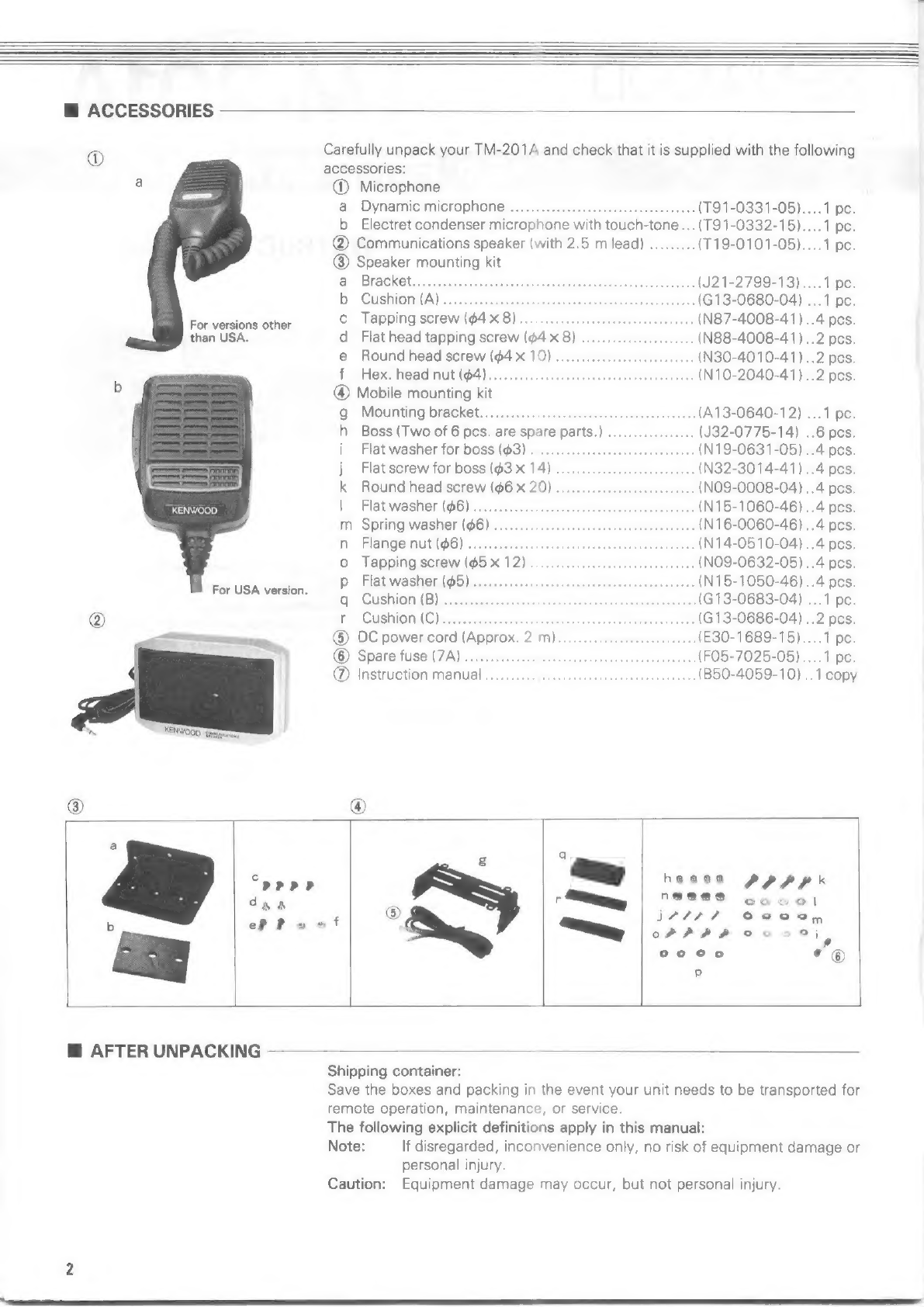
manuals.online logo
Brands
  1. Home
  2. •
  3. Brands
  4. •
  5. Kenwood
  6. •
  7. Transceiver
  8. •
  9. Kenwood TM-201A User manual

Kenwood TM-201A User manual

Other manuals for TM-201A

4

Other Kenwood Transceiver manuals

Kenwood TM-415A User manual

Kenwood

Kenwood TM-415A User manual

Kenwood NEXEDGE NX-820G User manual

Kenwood

Kenwood NEXEDGE NX-820G User manual

Kenwood TS-480 User manual

Kenwood

Kenwood TS-480 User manual

Kenwood TK-7302 User manual

Kenwood

Kenwood TK-7302 User manual

Kenwood TK-5210G K User manual

Kenwood

Kenwood TK-5210G K User manual

Kenwood TH-25 Series User manual

Kenwood

Kenwood TH-25 Series User manual

Kenwood ProTalk TK-3100 User manual

Kenwood

Kenwood ProTalk TK-3100 User manual

Kenwood TM-D700A User manual

Kenwood

Kenwood TM-D700A User manual

Kenwood TS-820 User manual

Kenwood

Kenwood TS-820 User manual

Kenwood TH-D75E User manual

Kenwood

Kenwood TH-D75E User manual

Kenwood TK-7100 User manual

Kenwood

Kenwood TK-7100 User manual

Kenwood TK-D200G User manual

Kenwood

Kenwood TK-D200G User manual

Kenwood TK-3202 User manual

Kenwood

Kenwood TK-3202 User manual

Kenwood TH-28A User manual

Kenwood

Kenwood TH-28A User manual

Kenwood TK-7180(H) User manual

Kenwood

Kenwood TK-7180(H) User manual

Kenwood TM-733A User manual

Kenwood

Kenwood TM-733A User manual

Kenwood TS-820 User manual

Kenwood

Kenwood TS-820 User manual

Kenwood TM-733A User manual

Kenwood

Kenwood TM-733A User manual

Kenwood TS-50S User manual

Kenwood

Kenwood TS-50S User manual

Kenwood TS-570D, TS-570S User manual

Kenwood

Kenwood TS-570D, TS-570S User manual

Kenwood NEXEDGE NX-300S User manual

Kenwood

Kenwood NEXEDGE NX-300S User manual

Kenwood NX-320 Series User manual

Kenwood

Kenwood NX-320 Series User manual

Kenwood TK-860G series Operating manual

Kenwood

Kenwood TK-860G series Operating manual

Kenwood TS-450S User manual

Kenwood

Kenwood TS-450S User manual

Popular Transceiver manuals by other brands

City Theatrical SHoW DMX SHoW Baby user manual

City Theatrical

City Theatrical SHoW DMX SHoW Baby user manual

Standart Horizont HX407 owner's manual

Standart Horizont

Standart Horizont HX407 owner's manual

B&G V90S quick start guide

B&G

B&G V90S quick start guide

VictelGlobal ALK300 series Operation manual

VictelGlobal

VictelGlobal ALK300 series Operation manual

Cactus Wireless Flash Transceiver V6 user manual

Cactus

Cactus Wireless Flash Transceiver V6 user manual

Yaesu FT-11R user guide

Yaesu

Yaesu FT-11R user guide

Skanti TRP 5000 instruction manual

Skanti

Skanti TRP 5000 instruction manual

ELECRAFT KX3 Installation and operation guide

ELECRAFT

ELECRAFT KX3 Installation and operation guide

American Lighting DMX512 quick start guide

American Lighting

American Lighting DMX512 quick start guide

Furuno FM-77 Operator's handbook

Furuno

Furuno FM-77 Operator's handbook

Yaesu FT-7B manual

Yaesu

Yaesu FT-7B manual

Mizuho MX-2 Operating & assembly instruction

Mizuho

Mizuho MX-2 Operating & assembly instruction

Blitz MJ-398U instruction manual

Blitz

Blitz MJ-398U instruction manual

Utilicom LongRanger 2050 Operator's manual

Utilicom

Utilicom LongRanger 2050 Operator's manual

Standart HX290UKA Service manual

Standart

Standart HX290UKA Service manual

Altronix Pace1PTM installation guide

Altronix

Altronix Pace1PTM installation guide

Kirisun PT2208 instruction manual

Kirisun

Kirisun PT2208 instruction manual

ELECRAFT KX2 manual

ELECRAFT

ELECRAFT KX2 manual

manuals.online logo
manuals.online logoBrands
  • About & Mission
  • Contact us
  • Privacy Policy
  • Terms and Conditions

Copyright 2025 Manuals.Online. All Rights Reserved.

KENWOOD
TM-201A
INSTRUCTION
MANUAL
KENWOOR,
Illustrated
is
the
USA
version.
You
are
the
owner
of
our
latest
product,
the
new
TM-201A
transceiver.
Please
read
this
instruction
manual
carefully
before
placing
your
transceiver
in
service.
The
unit
has
been
carefully
engineered
and
manufactured
to
rigid
quality
stan-
dards,
and
should
give
you
satisfactory
and
dependable
operation
for
many
years.
CONTENTS:
TDs,
«
FEAT
RES
ssn
dinassmpreedenelinadvanntivan
itn’
3
2.
CONTROLS
AND
THEIR
FUNCTIONS
........ccccccccseeerreee
4
3.
INSTALLATIONS
AND
CONNECTIONS
.............00cccccees
)
hes
NPP
TION:
aia
ns
apsislearene
each
daghareanaastritcananiutsan
armen
iieans
13
5.
MAINTENANCE
AND
ADJUSTMENT..............cs0eeeeenee
18
.
BECESSORIES
0:
swissswenneairannsh
dina.
apmuenteeterilemninteannue
tS
75
SBLOCKIDIAGHAM
snus
sstsns
saa
yialdasg
RUMOR
eens
22,23
8.
SPECIFICATIONS
@
ACCESSORIES
oO
Carefully
unpack
your
TM-201A
and
check
that
it
is
supplied
with
the
following
accessories:
a
@)
Microphone
a
Dynamic
Microphone
..............:2sceenneceereaw
swenne
(T91-0331-05)....1
pe.
b
Electret
condenser
microphone
with
touch-tone...(T91-0332-15)....1
pc.
@
Communications
speaker
(with
2.5
m
lead)
.........
(T19-0101-05)....1
pe.
@®
Speaker
mounting
kit
@
‘BraGhG
lias:
sinsunonuesdsneasteevsheliabbecetsncmemeannasssacicce
(J21-2799-13)....1
pe.
B:
(CUSHION)
cmreigadethwrds
aves
easmamyeerapmadaenatwse
(G13-0680-04)
...1
pe.
Forverdionsacher
c
Tapping
screw
(4x
8)...........
..
(N87-4008-41)
..4
pes.
than
USA.
d
Flathead
tapping
screw
($4
x
8)
(N88-4008-41)
..2
pes.
e
Round
head
screw
(64
X
10)
........
cece
seen
(N30-4010-41)..2
pes.
Ff
Aexcthede
MUtdS4
iscsi
vesciasauierssivveuniiesvadainwans
(N10-2040-41)..2
pes.
b
@
Mobile
mounting
kit
G
MOURNE:
DEACKEt.
incnererneseainicainnsiaiienanine’saiineins
(A13-0640-12)
...1
pe.
h_
Boss
(Two
of
6
pcs.
are
spare
parts.)
..
..
(J32-0775-14)
..6
pes.
i
Flat
washer
for
boss
(@3)
...........cccceeceeeeenee
een
ene
(N19-0631-05)..4
pes.
j
Flat
screw
for
boss
(63.
X
14)...
ccesceeceesaeeee
ees
(N32-3014-41)..4
pes,
k
Round
head
screw
(6
x
20)
.
..
(NO9-0008-04)
..4
pes.
KENWOOD
|
Flat
washer
(#6)...........
..
(N15-1060-46)
..4
pes.
m
Spring
washer
(#6)
.......
..
(N16-O0060-46)
..4
pcs.
n
Flange
nut
($6)
............
..
(N14-0510-04)
..4
pes.
©
Tapping
screw
($5
x
12)
..
(NO9-0632-05)
..4
pes.
’
p
Flat
washer
($5)...........
us
..
(N15-1050-46)
..4
pes.
ForUSA'version.
Cushion.(B),
...
eoaaetine
_.(G13-0683-04)
...1
pc.
f
CUSHIGR
WO)
icadapncsaitinsnen
ie
..
(G13-0686-04)
..2
pes.
®
DC
power
cord
(Approx.
2
m)...
.
(E30-1689-15)....1
pe.
©
Spare
fuse
(7A)
............
..(FO5-7025-05)....1
pe.
@
Instruction
manual
..(B50-4059-10)
..1
copy
haaaa
PPP
R*
q
wy
PPPrP
,
ey
"@@@8
gucoal
dig.
.
ee
;
®
jrrr7e
evo,
*
1.
“
oP
PPP
Coa),
e©oo°o
*
©
@
AFTER
UNPACKING
Shipping
container:
Save
the
boxes
and
packing
in
the
event
your
unit
needs
to
be
transported
for
remote
operation,
maintenance,
or
service.
The
following
explicit
definitions
apply
in
this
manual:
Note:
If
disregarded,
inconvenience
only,
no
risk
of
equipment
damage
or
personal
injury.
Caution:
Equipment
damage
may
occur,
but
not
personal
injury.
1.
FEATURES
¢
Compact,
slim
transceiver
for
easy
mobility
¢
Microcomputer
provides
multi-frequency
control
functions
©
Dual
function
keyboard
facilitates
memory
recall
(MR)
¢
High
reliability
by
using
PC
boards
for
each
unit;
high
sensitivity
(12
dB
SINAD
0.22
uV)
front-end
using
GaAs
FETs
©
Quality
sound
for
transmission
and
reception
¢
HI/LOW
switch
controls
output
power
©
Repeater
operation
¢
Extended
frequency
range*
1.
Coaxial
connector
with
cable
greatly
reduces
effective
depth
when
connec-
ting
an
antenna
cable.
2.
External
speaker
system
allows
installation
in
any
place.
3.
Remote
frequency
control
unit
(FC-10)
extends
your
operation
facility,
.
Five
channel
memories
plus
COM*
channel
can
be
recalled
at
will.
.
ALERT
function
monitors
memory
channel
1
(M1).
.
Memory
scan
operation
(MS)
from
memory
channels
1
through
5.
.
Programmable
scan
within
the
frequency
range
selectable.
.
1
MHz
step-up
function
(MHz).
.
VFO
A
in
5
kHz
(25
kHz;
for
European
and
British
versions)
steps;
VFO
B
in
5
kHz
steps.
7.
Beeper
indicates
each
of
7
modes.
aahWN—
ee
ee
|
Uy
i
|
Eieh
y
POWER/VOL
SQUELCH
a
.
External
communications
speaker,
77
mm
in
dia.,
supplied.
2.
Maximum
3%
modulation
distortion
ensures
good
quality
transmit
signal.
1.
COM"*
system
facilitates
access
to
repeaters
with
the
TU-3
unit*
(option)
in-
stalled.
2.
The
TU-3
2nd
tone
frequency
(one
of
37
frequencies
selectable)
intercon-
nected
with
the
TX
OFFSET
system
enables
access
to
a
repeater.
3.
The
REV
switch
monitors
direct
signal.
Covers
142.0~
149.0
MHz
in
5
kHz
steps.
*
European
and
British
versions
excluded.
2.
CONTROLS
AND
THEIR
FUNCTIONS
4
[-
7
IL
Note:
Illustrated
is
a
version
other
than
that
of
Europe/England.
(3)
@
@
ae
6
j
POWER/VOL
SQUELCH
@
FRONT
PANEL
@
Tuning
control
(VFO)
O)
VOL/POWER
©
©)
SQUELCH
@
Keyboard
(a)
MR/M1
(memory
recall)
key
ce
v1
|
fs)
(memory
scan)
Ss
V2]
LJ
Used
to
set
frequency
for
transmission
and
reception.
One
step
(depending
upon
VFO
step)
per
one
click
shifts
up
and
down.
During
memory
recall
opera-
tion,
turning
this
control
restores
the
operation
to
VFO
with
the
frequency
displayed.
Note:
One
click
rotation
shifts
the
displayed
frequency
one
step
up
or
down.
However,
the
frequency
step
may
not
be
changed
due
to
microcom-
puter
transient.
Power
ON-OFF
switch
and
volume
control
are
combined.
Turning
the
control
fully
counterclockwise
will
turn
the
power
OFF.
Clockwise
rotation
will
in-
creases
the
volume.
The
squelch
control
is
used
to
eliminate
noise
during
no-signal
time.
Normally,
this
control
is
adjusted
clockwise
until
the
noise
disappears.
For
scan
opera-
tion,
this
control
must
be
set
to
the
threshold
point.
Used
to
recall
memory
channe
When
depressed,
memory
channel
1
is
recalled.
The
MR
indicator
lights
to
show
the
memory
recall
is
in
operation.
When
recalling
one
of
the
memories
in
M2
~M5,
depress
the
MR/M1
key
then
the
corresponding
key
of
M2
~
M5.
Used
to
initiate
scan
for
memory
channels.
During
memory
recall
operation,
depressing
this
key
recalls
memory
CH2.
During
memory
scan,
depressing
this
key
recalls
the
next
memory
channels.
‘©
MHz/M3
(1
MHz
up)
key
M3
|
aaa
(d
M/M4
(memory
input)
key
rm
M4
|
aan
|
©)
AL/MS
(alert)
key
AC
ss]
(f)
A/B
(VFO
'A/B
selection,
scan
stop)
key
A/B
|
©
MIC
connector
(8
pin)
@
COM
(common
channel)
key
For
users
other
than
Europe
and
England.
COM
ES
TONE
switch
(For
British
version)
TONE
When
depressed,
the
displayed
frequency
shifts
up
1
MHz.
During
memory
recall
operation,
depressing
this
key
recalls
memory
CH3.
Used
to
store
the
desired
frequency
in
memory
channel
(and
in
COM
channel:
European
and
British
versions
excluded).
For
memory
input,
refer
to
page
15.
During
memory
recall
operation,
depressing
this
key
recalls
memory
CH4,
In
memory
CH4,
transmit
and
receive
frequencies
are
stored
independently
for
odd
split
operation.
When
depressed,
the
ALERT
indicator
lights
to
show
alert
operation
is
in
pro-
gress.
Depressing
this
key
again
releases
this
operation.
For
more
details,
refer
to
page
17.
During
memory
recall
operation,
depressing
this
key
recalls
memory
CH5.
Memory
channel
5
is
used
for
odd
split
operation
as
for
memory
channel
4.
The
frequencies
(transmit
and
receive)
stored
in
CH5
designate
frequency
range
limits
for
programmable
scan
operation.
For
more
details,
refer
to
page
15.
As
shown
in
the
table,
this
key
provides
three
types
of
operation.
Mode
A/B
key
functions
VFO
Each
time
the
key
is
depressed,
VFO
A
and
B
are
selected
alternately.
MR
When
depressed,
VFO
before
memory
recalled
is
restored.
SCAN
When
depressed,
scan
is
released.
Microphone
audio
input.
Frequency
UP/DWN
control
and
PTT
lines
are
includ-
ed.
Pin
assignments
of
the
MIC
connector
are
shown
below.
©
8C(+8Vv)
(@
UP
(10
mA
Load)
g—F
Vi
~~
@
DWN
(NC
ey
})
W
@'STBYIFTT)
Note:
Do
not
apply
voltage
to
@
GND
(MIC)
——MIE
pins
2, @,
and
@.
(8)
GND
The
pin
‘5
should
not
be
shorted
nor
applied
any
voltage.
FRONT
VIEW
When
the
key
is
depressed,
the
common
channel
can
be
recalled
any
time.
This
channel
can
be
changed
to
your
desired
frequency.
For
common
channel
replacement,
refer
to
page
15.
To
release
common
channel
operation,
depress
this
key.
No
other
key
can
release
the
operation.
When
the
optional
TU-3
tone
unit
is
installed,
the
1st
tone
frequency
is
emitted
when
operating
the
COM
channel.
When
this
switch
is
pressed,
the
repeater
control
tone
burst
signal
(1,750
Hz)
is
emitted
for
about
0.5
seconds
at
the
beginning
of
each
transmission.
TONE
switch
(For
European
version)
When
this
switch
is
pressed,
the
repeater
control
tone
signal
(1,750
Hz)
cir-
TONE
cuit
is
activated
and
the
unit
is
set
in
the
transmit
mode.
@
HI/LOW
switch
<=
—
LOW
@
Display
®
Frequency
display
Scan
indicator
VFO
B
indicator
MR
indicator
ALERT
indicator
ON
AIR
indicator
BUSY
indicator
S
&
RF
meter
Note:
Illustrated
is
a
version
other
than
that
of
Europe/England.
@
9@
|
POWER/VOL
SQUELCH
HI
setting:
This
setting
allows
the
transmitter
to
transmit
power
output
up
to
25
watts.
LOW
setting:
This
setting
allows
the
transmitter
to
transmit
power
output
approx.
5
watts.
(a)
(d
(e
p
SEN
TEMET
BANS
GEN,
MR
a0
ALERT
a8
ON
AIR
t
MO
oo
M0
®
©
&e
h
During
VFO
A
or
B,
frequency,
for
example,
145.02
is
displayed
in
four
digits
as
‘5.020
"',
5.020
During
MR
(M1
—
M5)
operation,
frequency,
for
example,
145.24
is
displayed
in
4
digits
as
‘'5.240"".
5.249
During
COM*
operation,
frequency
is
displayed
in
four
digits.
At
this
time,
zero
at
the
last
digit
is
half
size.
*
European
and
British
versions
excluded.
During
scan
operation,
this
dot
flashes.
n
operation
other
than
scan,
this
dot
lights
to
show
MHz.
Lights
when
VFO
B
is
in
operation.
Lights
during
memory
recall
operation
(M1
—
M5,
MS).
Lights
during
alert
operation.
Lights
when
transmitting.
Lights
during
reception
with
squelch
opened.
This
can
be
used
to
see
if
the
channel
is
busy
or
not.
ndicates
the
incoming
signal
strength
by
LEDs
during
reception.
During
transmission,
LEDs
light
to
show
the
RF
output
level
strength.
With
the
HI/LOW
switch
HI,
al!
LEDs
light.
With
the
HI/LOW
switch
LOW,
two
to
four
LEDs
light.
@
REV
switch
Used
to
reverse
the
repeater
shift
(+600
kHz)
to
monitor
a
signal
coming
to
a
REV
repeater.
Setting
this
switch
to
ON
in
simplex
operation
locks
the
displayed
fre-
O
quency
regardless
of
VFO,
keyboard,
and
COM*.CH
operations.
(*
European
and
British
versions
excluded.)
@
TX
OFFSET
switch
Used
to
set
transmit
frequency
(+600
kHz)
shifted
from
the
displayed
receive
frequency
when
transmitting.
For
operation
other
than
that
of
a
repeater,
place
this
switch
to
the
‘’S’’
posi-
fou
tion.
This
equalizes
the
transmit
frequency
with
the
receive
frequency.
aa
“4+
setting
shifts
+600
kHz;
‘‘—"’
setting
shifts
—600
kHz
from
the
receive
frequency
when
transmitting.
This
operation
is
only
effective
in
VFO
and
MR
(M1~M3)
operations.
If
a
shift
frequency
goes
beyond
the
operating
frequency
range
when
depress-
ing
the
PTT
switch
to
transmit,
a
beep
will
sound
three
times
to
indicate
the
misoperation.
However,
transmit
frequency
is
emitted
in
simplex
mode.
*With
the
optional
TU-3
tone
unit
installed,
either
‘‘+‘'
or
‘‘—"'
setting
of
the
TX
OFFSET
switch
interconnects
the
TU-3
2nd
tone
frequency
setting.
(*
European
and
British
versions
excluded.)
@
REAR
PANEL
©
®
@
ANT
connector
lead
Connect
a
50-ohm
antenna
to
this
terminal.
@
DC
Power
Terminal
DC
power
input
terminal.
Connect
the
supplied
power
cord
with
plug.
Input
voltage
is
13.8
V
DC.
Observe
plus
(+)
and
minus
(—)
polarity!
@®
SP
Terminal
Connect
the
supplied
8
ohm
speaker
to
this
jack.
@
RIGHT
SIDE
PANEL
@®
Remote
jack
Used
to
connect
the
optional
FC-10
unit,
controlling
the
operation
frequency.
7
@
MICROPHONE
(For
U.S.A.
version)
@®
UP/DWN
switches
@®
PTT
Switch
@
16
Touch-Tone
Keys
(Auto-
patch
operation)
H@
MICROPHONE
(For
versions
other
than
U.S.A.)
@®
UP/DWN
switches
@®
PTT
switch
1)
2)
3)
Mic-hook
button
Microphone
Touch-tone
encoder
Depressing
the
UP
or
DWN
key
momentarily
shifts
the
displayed
frequency
one
step
up
or
down.
Holding
the
key
depressed
continuously
shifts
the
frequency
up
or
down.
Holding
the
UP
or
DWN
key
depressed
for
about
one
second
initiates
scan
Operation.
The
scan
direction
depends
on
the
UP
or
DWN
key
operated.
Depressing
the
UP
or
DWN
key
during
MR
operation
will
change
the
opera-
tion
from
MR
to
VFO.
Press-to-talk
switch
is
used
for
transmission.
This
will
also
releases
scan
opera-
tion.
When
releasing
the
SCAN
operation,
transmission
is
inhibited.
Used
to
activate
the
touch-tone
encoder.
1)
2)
3)
®
|
Depressing
the
UP
or
DWN
key
momentarily
shifts
the
displayed
frequency
one
step
up
or
down.
Holding
the
key
depressed
continuously
shifts
the
frequency
up
or
down.
Holding
the
UP
or
DWN
key
depressed
for
about
one
second
initiates
scan
operation.
The
scan
direction
depends
on
the
UP
or
DWN
key
operated.
Depressing
the
UP
or
DWN
key
during
MR
operation
will
change
the
opera-
tion
from
MR
to
VFO.
Press-to-talk
switch
used
for
transmission.
This
will
also
release
scan
opera-
tion.
When
releasing
the
scan
operation,
transmission
is
inhibited.
3.
INSTALLATIONS
AND
CONNECTIONS
@
ANTENNA
The
performance
of
the
transceiver
depends
upon
the
type
of
antenna
to
be
us-
ed.
To
ensure
the
maximum
performance
of
the
TM-201A,
select
a
suitable
antenna
and
adjust
it
for
low
VSWR.
@
MOBILE
INSTALLATION
e
Interconnection
The
TM-201A
is
equipped
with
a
speaker.
Y
=
ie
I
JUULULUUU
AI
[
¢
Wiring
on_
installation
on
the
car.
Make
sure
the
positive
(+) and
negative
(—)
lead
polarities
are
correct
when
wiring
to
the
battery.
+)
Red
+
Red
a
Fuse
(20
A)
Engine
compartment
«——
H
———+
Passenger
compartment
|
‘Chassis
or
Fire
wall
Select
the
location
where
the
power
cable
is
protected
from
heat,
moisture
or
abrasion
secure
the
cable.
Make
sure
the
cable
does
not
directly
con-
tact
the
edge
of
the
hole
by
using
a
grommet.
Notes:
©
Before
installing
the
power
cable,
be
sure
to
remove
the
negative
lead
from
the
battery
for
safety.
e
After
installation
and
wiring,
be
sure
to
double
check
for
correct
installation
before
reconnecting
the
negative
lead
to
the
battery
terminal.
°
If
the
fuse
opens,
be
sure
to
check
that
each
conductor
has
not
been
damaged
by
short-circuiting,
etc.
Then
replace
with
a
new
fuse
of
the
same
rating.
°
After
completing
the
wiring,
wrap
the
fuse
holder
with
tape
to
protect
against
moisture.
*
Do
not cut
out
the
fuse
even
if
the
power
cable
is
too
long.
@
If
the
wiring
hole
in
the
fire
wall
or
chassis
is
too
small,
disassemble
the
fuse
holder
to
thread
the
wire
through
the
hole.
From
passenger
compartment
—=
a
The
lead
like
this
®
Installation
location
a
Using
the
supplied
mounting
bracket,
install
the
transceiver
under
the
dashboard
or
on
the
side
of
the
console
in
your
car
as
shown.
|
Console
lf
your
car
is
equipped
with
an
electronic
fuel
injector,
the
ae
uae
a4
of
transceiver
should
be
as
far
from
the
control
equipment
as
possible.
jashboar
Mi
COMMUNICATIONS
SPEAKER
INSTALLATION
Note:
To
keep
driving
safe,
do
not
install
the
speaker
to
the
ceiling.
Speaker
Cushion
(A)
Example
2-3
Securing
bracket
Example
2-2
Example
2-1
Pa
(to
$4)
a
A
‘7
Mounting
Mounting
surface
surface
oo
°
©
©}
Tapping
screw
foume)
fo)
5
|
Round
head
x8
screw
is
($4
10)
Bracket
Tapping
screw
(4x
8)
Faeroe
226
ae
1
2)
3)
®
Installation
procedure
4)
5)
Fig.
a
Boss
securing
Flathead
Boss
Flat
screw
washer
Be
sure
to
use
flat
washers.
Otherwise,
in-
stallation
to
the
mounting
bracket
is
not
done
well.
However,
when
stack
installation
with
the
TM-401
is
attempted,
do
not
use
these
washers
since
the
stack
plates
are
used.
we
Cushion
(A)
Cushion
(A)
Example
2-8
Speaker
B.
)
Tl
w
|
Cushion
(A)
Secure
the
bosses
on
each
side
with
4
flat
head
screws.
(Fig.
a)
Affix
the
cushion
(c)
on
each
side
of
the
mounting
bracket.
(Fig.
b)
Secure
the
mounting
bracket
to
a
car
chassis
as
shown
in
Fig.
c.
When
installing
the
bracket,
be
sure
the
front
part
of
the
bracket
faces
you.
Insert
the
transceiver
as
shown
in
Fig.
d
so
the
bosses
on
the
transceiver
slide
into
the
grooves
of
the
mounting
bracket.
To
stack
with
the
TM-401A
(70
cm),
first
secure
the
supplied
stack
plate
to
the
TM-201A
with
bosses
then
stack
the
TM-401A,
second
insert
the
stacked
transceivers
as
shown
in
Fig.
d
so
the
bosses
on
the
upper
transceiver
slide
into
the
grooves
of
the
mounting
bracket.
Fig.
b
Cushion
attachment
Affix
the
cushion
(B).
Affix
the
cushion
(C)
on
each
side.