Assa Abloy SecureComm HKC GSM-WIFI U User manual

www.hkcsecurity.com
Security
Safe & Secure
An ASSA ABLOY Group brand
Universal GSM/WiFi
IP Communicator

2
Setting-up SecureComm...........................................................................................3
Commissioning the GSM-WiFi U - Standalone Mode................................................3
How to commission u
...........................................................10
......11
Technical Specifications...........................................................................................26
sing the
he HKC APP...........................
......................................................
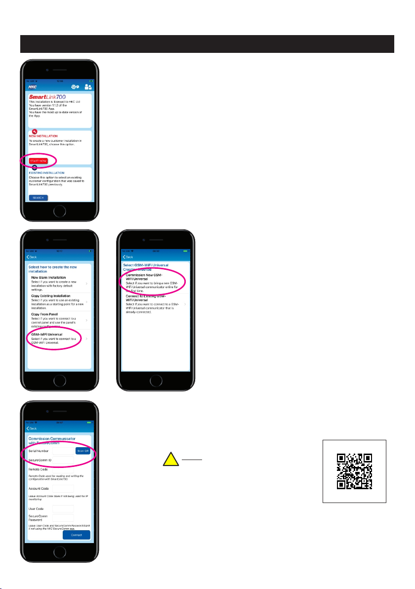
SmartLink700 app...........................................4
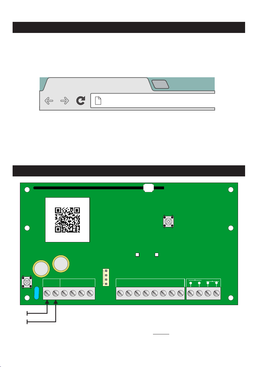
Downloading t ................................................8
GSM-WiFiU Inputs & Outputs......... ........9
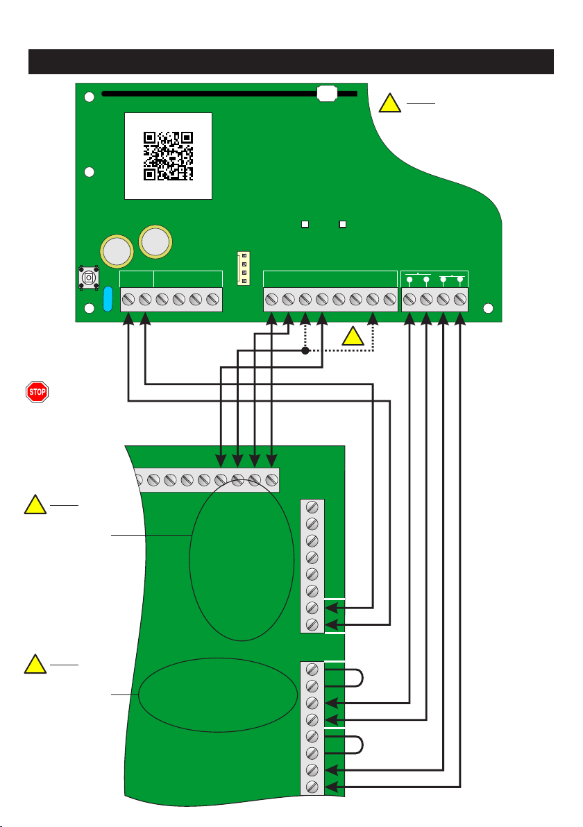
Example of Standalone Wiring........
Commissioning GSM-WiFi U - SecureWatch Mode.............................................
Wiring to SecureWatch Panel.....................................................................12
Menu Map for SecureWatch Panels.............................................................13
Communicators Menu - SecureWatch Panels.............................................14
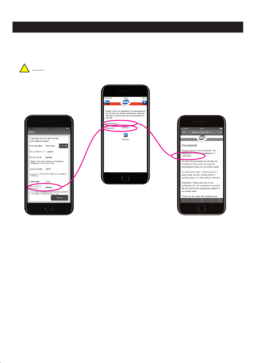
SecureComm Menu - SecureWatch Panels................................................16
Commissioning GSM-WiFi U - SecureWave Mode....................................................18
Wiring to SecureWave Panel.......................................................................19
Menu Map for SecureWave Panels..............................................................20
Communicators Menu - SecureWave Panels...............................................21
SecureComm Menu - SecureWave Panels..................................................23
GSM & WiFi Status LEDs.............................................................................26
Contents
WARNING
While this system has been designed to the highest standards it does not offer guaranteed protection against burglary, fire or carbon
monoxide. Any alarm system is subject to compromise or failure to activate for a variety of reasons. Therefore, good installation practices and
regular maintenance are essential to ensure continuous satisfactory operation of the system. The transmission of messages is dependent on
the telecom service provider. HKC Security Ltd. cannot guarantee successful messaging. Messages which remain undelivered when the
validity period expires are discarded. The validity period is the time the message is submitted plus 12 hours.
COPYRIGHT
© HKC Security Ltd. All Rights reserved. No part of this publication may be reproduced, transmitted, stored in a retrieval system or translated
in another language in any form or by any means - electronic, mechanical or otherwise without the prior written permission of HKC Security
Ltd.
DISCLAIMER
HKC Security Ltd. makes no representations or warranties with respect to the contents hereof and specifically disclaim any implied warranties
of merchantability or fitness for any particular purpose. Further, HKC Security Ltd. reserve the right to revise this publication and to make
changes from time to time in the contents hereof without obligation of HKC Security Ltd. to notify any person of such revision.
This marking certifies that this product has been tested in a representative system complying with the requirements laid down in EMC
directive 2014/30/EU, RE Directive 2014/53/EU, RoHS directive 2011/65/EU and their amendments.
GSM-WiFiU Installation Manual Rev 2. 11th of November, 2020

SecureComm is HKC’s cloud-based communications service which greatly
enhances the capabilities of your system.
There are essentially 3 phases to setting up SecureComm connectivity. The first is to
setup the billing arrangements with the end user. Go to your internet browser and
type securecomm.hkc.ie into the address bar as illustrated.
Power-up the communicator as illustrated then press and hold the
Connect/Reset button for 5 seconds approx. until the WiFi and
GSM Status LEDs flash red - then release. When the LEDs are a
solid red, the unit has been factory defaulted. Next, briefly press the Connect/Reset
button again. This forces the unit to establish a GSM link to the SecureComm server
in the background. Initially, the GSM Status LED flashes orange for 15 minutes.
Here you will find an intuitive series of prompts which sets up basic account details.
Once
the process is complete, you will be issued with an installation ID number.
The second phase involves physically configuring the system i.e. powering-up the
GSM-WiFi Unit - see below and the following pages:
Also, if the end user wants, take this opportunity to select IP Reporting
Keep this
number safe for the moment
.
, it will be required later.
Setting up SecureComm
New Tab
securecomm.hkc.ie
X
Commissioning the GSM-WiFi U - Standalone Mode
112
2 3 4 5
D6
C
Inputs Outputs
Connect/Reset
Button
Press 1 sec. to Connect
or
Hold to Default
GSM Status
WiFi Status
Tamper
7
+ B 8
-A
12V
0V
100811811
S/N#
3

Essentially, you now have 15 minutes to match the GSM-WiFiU
communicator being commissioned to the relevant
SecureComm account.
Using the SmartLink700 app press the New Installation
START NOW icon
Next, select the GSM-WiFi Universal
option followed by the Commission New
GSM-WiFi Universal option.
Then, either type-in the serial number or scan the QR code
pattern from the label fitted on the circuit board.
Note: To scan the pattern, press the
Scan QR icon and place the phone’s
camera in front of the label. The
Serial Number box will auto-populate.
Type-in the SecureComm installation ID number - the one you
got when you established the billing details (page 3).
Commissioning the GSM-WiFi U - Standalone contd.
100811811
S/N#
!
1234567
100811811
4

As a minimum, you will also need to enter a Remote Code. This
remote access code will be required should you need to
reconfigure the unit in the future. Minimum length is 4
characters. Maximum length is 16. The characters can be letters
or numbers.
If you are enabling IP reporting then contact your monitoring
company (ARC), get an account number and put it into Account
Code section here.
Note: Remember to select the IP reporting option in the
securecomm.hkc.ie portal.
If the end user wants the option of control via the HKC APP they
will need a 4 to 6 digit (i.e. numerals) User Code - similar to a
traditional arm/disarm code. The “0" digit may be used.
A SecureComm Password, chosen by the installation engineer,
must also be entered. The minimum length of the password is 4
characters. Maximum length is 16. The characters can be letters
or numbers.
when the HKC APP is being set up.
Keep this password safe for the moment, it will
be required
Finally, press the Connect icon.
Commissioning the GSM-WiFi U - Standalone contd.
1234567
1234567
100811811
100811811
18867
18867
2222
2222
Wait a few moments while the customer’s details are read from
the SecureComm server.
Note: If the unit cannot connect to the SecureComm server, you may
have to briefly press the Connect/Reset button again.
Note: When the unit is successfully commissioned the GSM Status LED
will flash green. Each flash represents 20% network coverage (e.g. 4
flashes = 80%).
1234567
100811811 !
!
!
5

Commissioning the GSM-WiFi U - Standalone contd.
The customer’s details will auto-populate the relevant fields.
When complete press the Save icon.
So far, the system is only setup using the GSM network. For full
connectivity it should also be connected to a WiFi network.
Therefore...
You will see the new site added to your customer list. To add
WiFi connectivity click on the customer in question - in this
example “Sheehan’s”.
Then click on the red cloud icon to connect to the communicator.
1234567
Sheehan’s
Vincent
Walsh
Mary Sheehan
Serial Number:
SecureComm ID:
Type:
Version: 1.0.0.19
GSM-WiFi Universal
1234567
100811811
6

Commissioning the GSM-WiFi U - Standalone contd.
Press the Scan WiFi Networks icon.
The system will take about 30 seconds to scan the premises for
WiFi routers. When complete, select the router in question, enter
the router’s password and press Connect.
Then go to COMMUNICATORS and select WiFi.
sheehan home (Signal Level: 5)
7
Note: When the unit is successfully connected, WiFi Status LED
will flash green. Each flash represents 20% WiFi coverage (e.g. 4
flashes = 80%).
!

Commissioning the GSM-WiFi U - Standalone contd.
1234567
100811811
1234567
End User’s phone
Installer’s phone Installer’s phone
Once the end user has downloaded the HKC APP they will be guided to a page
where they input the installation ID (the one from page 3 of this manual) and the
password chosen by the installation engineer (from page 5 of this manual).
When done, press the Connect icon. The HKC APP is now ready to go.
To login to the site, enter the User Code that was programmed on page 5.
The GSM-WiFiU unit is now live and ready for the 3rd and final phase which
involves the end user downloading the HKC APP from: Google play®, or Apple’s
App Store®.
Note: To find the HKC APP quickly, search for HKC SecureComm in both stores.
!
8

112
2 3 4 5
D6
C
Inputs Outputs
Connect/Reset
Button
GSM Status
WiFi Status
Tamper
7
+ B 8
-A
12V
0V
0V 0V 0V 0V 0V 0V 0V 0V
100811811
S/N#
Commissioning the GSM-WiFi U - Standalone contd.
When an input is pulled down to 0V as illustrated, it is in the normal Restored state.
Removing this 0V i.e. when a switch is opened, the voltage on the terminal will pull
up to 3V and will Activate the input. These inputs are fully programmable through the
SmartLink700 App. The input triggers can also be changed so that they will activate
when 0V is applied and restore when 0V is removed. It is also possible to apply 12V
to an input to activate it. Input activations can also be delayed by up to 60 minutes.
The default input types are:
There are also 2 relay Outputs on the unit. Output 1 is a programmable Normally
Open output that by default follows the onboard tamper switch, and will also open if
a fault is detected on the GSM or Wi-Fi path. This output will be closed when the
tamper is closed and there are no faults detected on the communication paths. This
output will open if power is lost to the unit.
These outputs are fully programmable through the SmartLink700 App. The outputs
can also be inverted if required.
Output 2 is normally closed-circuit. It can be wired into a Key input and can be
controlled by the HKC app i.e., when it goes open-circuit it will arm a typical control
panel and when it goes closed-circuit it will disarm the panel.
Ireland
1 Fire
2 Panic
4 Arm/Disarm
5 Zone Inhibit
6 Mains Fail
8 Tamper
3 Verified Alarm
7 Pre-Alarm
United Kingdom
1 Fire
2 Panic
4 Open/Close
5 Zone Omitted
6 Mains Fail
8 Tamper
3 Intruder Alarm
7 Confirmed Alarm
9
Note: Slightly different
phraseology used in
Ireland and the UK.
!

Example of Standalone Wiring - non-EN compliant
112
2 3 4 5
D6
C
Inputs Outputs
GSM Status
WiFi Status
Tamper
7
+ B 8
-A
100811811
S/N#
+
-
12V
Control Panel
Fire o/p
Panic o/p
Alarm o/p
Arm/Disarm o/p
Zone programmed
for “Line Fault”
Zone programmed
for “Key”
Note: Given
that a GSM or
WiFi fault is
more likely
than a tamper
activation,
choose this
zone for “Line
Fault”.
Note: Make
sure these are
programmed
as positive
trigger.
!
!
!
Note: Choose either input 3
or 7 depending on your
monitoring company’s
preferred “channel” for a
verified alarm signal.
!
10
Remove the
mains and
battery
supply before
fitting the
GSM-WiFiU
unit

Commissioning GSM-WiFi U - SecureWatch Mode
So far we have dealt with commissioning a standalone system. In this section we
will look at commissioning using a SecureWatch panel.
You will need to go to your
And if you want to control the system via the HKC APP then you will need to set it
up as per page 8.
However, one advantage of connecting the unit to a SecureWatch panel is that the
communicator can be commissioned through the panel’s engineering menu
structure. You can not use the SmartLink700 app for this task.
Wire the GSM-WiFiU communicator to the SecureWatch panel as illustrated in the
next page.
internet browser and type securecomm.hkc.ie as before
to setup the SecureComm billing arrangements - see page 3.
11

1
1
22
3
4
5D
6C
Inputs
Outputs
Tamper
7
+
B
8
-
A
100811811
S/N#
DCBA +
-
SW-812 or
SW-1212 or
SW-16120 Control Panel
Plug Comms
Card onto
Serial Port
Z6 Z7
Wiring to SecureWatch Panel
12V
12
Remove the
mains and
battery supply
before fitting the
GSM-WiFiU unit
Note: For SW-812 make sure software is V7.32 or later.
For SW-16120 make sure software is V2.0 or later.
Note: For tamper purposes,
wire as illustrated and
programme the zone input
of your choice as a Tamper
(go to Zone Types in the
Zone Menu).
!
!

Menu Map for SecureWatch Panels
9 Serial Port Menu
8 Sys. Opts. Menu
7 Outputs Menu
6 Timers Menu
5 Users Menu
4 Point Menu
3 Zone Menu
2 Devices Menu
1 Service Menu
2 Communicators
2 Options
2 WiFi
1 Comms Overview
1 Status
1 GSM
5 Default
4 Test SMS
3 SecureComm
3 IP Monitor
2 Comms Option Menu
1 Modem Card Menu
5 Comms Service Menu
4 Panel Print Menu
6 Dialler Menu
3 Remote User Menu
The GSM-WiFiU communicator can be commissioned through the panel’s
engineering menu structure - see above.
Go into the Engineer mode and scroll down to Serial Port Menu and press YES.
Next, scroll to Dialler Menu, press YES and scroll to Communicators - again,
press YES.
To get the full benefit of the unit, go to both the GSM and WiFi sections of the menu
and press YES in both instances. The first time you enter these sub-menus you will
be asked to enable the GSM and WiFi capabilities of the device.
2 IP Address
2 Disable GSM
2 Disable WiFi
2 Fault Delay
2 Fault Delay
2 Monitor Faults
2 WiFi
1 DHCP Enabled
1 Status
1 Status
1 Monitor Signal Yes
Yes
10m
10m
Yes
Yes
Yes
1 Monitor Signal
1 IP Settings
1 GSM
5 DNS Server
4 Gateway
4 GMS Network Scan
4 WiFi Network Scan
4 Tamper
3 Subnet Mask
3 Options
3 Options
3 Jam Detect
3 Tamper
If you enable the GSM first, the device
the SecureComm service in the background.
Note: You have to manually Scan for WiFi if you opt to only enable the WiFi system
You will be prompted to key-in the installation ID number - the one you got when you
established the billing details (page 3). You will then be prompted accept a randomly
generated 10-digit alphanumeric. This password can be changed by pressing NO.
Note: Passwords can be 6 to 16 alphanumerical characters in length. Lower & upper cases allowed
We recommend using a strong password and avoiding simple passwords such as “alarm”,
“1111" etc.
will automatically start to establish its links to
!
!
13

Communicators Menu - SecureWatch Panels
This sub-menu disconnects the GSM path from . SecureComm
When you select the GSM Network Scan sub-menu, the
system searches for GSM signals in your vicinity and connects
to the strongest.
Monitor Signal will flag a fault in the event of a GSM network
failure. By default it is set to YES.
You can delay the notification of a fault by going to the Fault
Delay sub-menu and keying-in a delay time in minutes. Useful
in areas of poor network coverage that are prone to occasional
brief dropouts. By default it is set to 15 minutes.
In this sub-menu you can turn off the Tamper signal from the
communicator. By default it is on i.e. YES.
Note: This Tamper switch is connected to Relay 1in SecureWatch Mode. A
Tamper condition will not be reported to the Panel via the Comms Card link.
Relay 1 should be wired to a Zone programmed as Tamper or wired to a Tamper
loop on a spare Zone. Turning off this option will disable the tamper switch and
keep Relay 1 permanently closed.
The GSM unit can detect and flag attempts at jamming the GSM
signal. In areas where the network is prone to high levels of
radio noise this feature can be turned off by deselecting Jam
Detect
Note: If you are using a GSM-WiFiU via the SecureComm service, the HKC
APP can notify you - on your smartphone - if there is jamming of the
GSM/GPRS path. SecureComm can also notify your monitoring centre. This
feature is enabled in the HKC APP.
96211 GSM Status
96212 Disable GSM
96213 Options
962131 Monitor Signal
962132 Fault Delay
962134 Tamper
96214 GSM N’work Scan
962133 Jam Detect
This sub-menu offers an overview of the SecureComm
connectivity and where you will find the Installation ID number.
!
!
Yes
10m
Yes
Yes
2 Disable GSM 2 Fault Delay2 WiFi
1 Status 1 Monitor Signal1 GSM
4 GMS Network Scan 4 Tamper
3 Options 3 Jam Detect
14

Communicators Menu - SecureWatch Panels - contd.
This sub-menu disconnects the WiFi path from . SecureComm
DHCP is enabled by default. This is an auto-configuration
protocol used on IP networks. When it is enabled, you do not
have to configure the other four sections i.e. the IP Address,
Subnet Mask, Gateway and DNS Server. We strongly
recommend that you leave the DHCP Enabled set to YES
unless you are installing the system on a site where the IT
department may want these configured in a particular way.
When you select the WiFi Network Scan sub-menu, the
system searches for WiFi signals in your vicinity for you to
choose from.
Monitor Signal will flag a fault in the event of a WiFi network
failure. By default it is set to YES.
You can delay the notification of a fault by going to the Fault
Delay sub-menu and keying-in a delay time in minutes. Useful
in areas of poor WiFi coverage that are prone to occasional
brief dropouts. By default it is set to 10 minutes.
In this sub-menu you can turn off the Tamper signal from the
communicator. By default it is on i.e. YES.
96221 WiFi Status
96222 Disable WiFi
96223 Options
96223 Options
962231 IP Settings
962232 Monitor Faults
9622321 Monitor Signal
9622322 Fault Delay
9622323 Tamper
This sub-menu offers an overview of the SecureComm
connectivity and where you will find the Installation ID
number.
2 IP Address 2 Disable WiFi
2 Fault Delay
2 Monitor Faults
2 WiFi 1 DHCP Enabled1 Status
Yes
10m
Yes
1 Monitor Signal
1 IP Settings
1 GSM
5 DNS Server
4 Gateway4 WiFi Network Scan
3 Subnet Mask3 Options
3 Tamper
96224 WiFi N’work Scan
15

2 Mains Delay
2 Timer
2 Test Period
2 Virtual RKP
2 GSM Poll Fault
2 Panic
2 Options
1 Alarm Delay
1 Message Call Monitoring
5s
1 Test Start
1 Password
55m
20s
Yes
Yes
Yes
Yes
Yes
Yes
Yes
Yes
1 LAN Poll Fault
1 Fire
1 Status
3 Notification
3 All Poll Fault
3 Alarm
x etc.
3 IP Monitor
2 Make Test Call
1 Account
5 IP Test Calls
4 Delays
6 Server Signals
7 AVI
3 Reports
SecureComm Menu - SecureWatch Panels
9631 SecureComm Status
This sub-menu offers an overview of the SecureComm
connectivity and where you will find the Installation ID
number.
If you need to change your SecureComm password then this
menu is where you can do this.
If you are enabling IP monitoring then contact your monitoring
company (ARC), get an account number and put it into
Account section here.
Note: Remember to select this option in the securecomm.hkc.ie
portal.
There is a virtual keypad available in the HKC APP. You may
want to disable this feature in which case you set Virtual
Keypad to NO. It is YES by default.
Normally the HKC APP will notify you of alarms and faults from
your system. You may want to disable this feature in which
case you set Notification to NO. It is YES by default.
Allows the installer to make a test call to the ARC without
having to create an event.
This is where the installer can tailor the report types to be sent
to the ARC. By default the following events are reported: Fire,
Panic, Alarm, Tamper, Mains, Low Battery, Faults and Inhibit.
The following are not: Set/Unset, Engineer Here, Tech. & Fire
Exit
9632 Options
9633 IP Monitor
96321 Password
96331 Account
96322 Virtual Keypad
96323 Notification
96332 Make Test Call
96333 Reports
!
16

2 Mains Delay
2 Timer
2 Test Period
2 GSM Poll Fault
2 Options
1 Alarm Delay
1 Message Call Monitoring
5s
1 Test Start
55m
20s
Yes
Yes
Yes1 WiFi Poll Fault
1 Status
3 All Poll Fault
3 IP Monitor
2 Make Test Call
1 Account
5 IP Test Calls
4 Delays
6 Server Signals
7 AVI
3 Reports
SecureComm Menu - SecureWatch Panels - contd.
By default, there is an Alarm Delay of 20 seconds. This is to
reduce false alarm reporting. Enter this sub-menu to change to
delay to a time (in seconds) of your choice.
By default, there is a Mains Delay of 55 minutes. During a
power-cut a mains fault will only be reported to an ARC if this
period is exceeded. Enter this sub-menu to change to delay to
a time (in minutes) of your choice.
During an installation, the installer can programme the system
to make its first test call to the monitoring centre at a specific
time into the future. Select Test Start and key-in the hours and
minutes of the first test call.
Following on from the first test call, subsequent test calls can
be made at a set interval. Select the number of hours of this
interval by keying-in a number in Test Period.
These settings allow the installer to tailor poll fault messages
being sent to the ARC. Depending on whether just one or both
of the GSM/WiFi communication paths are stable you may
choose to turn off a polling fail report.
WiFi Poll Fault: When enabled, if the Wi-Fi communicator
loses connection to the SecureComm Server for longer than
the poll fail time on the chosen IP monitoring package, the
SecureComm Server will send a "LAN Poll Fail" IP Signal to
the monitoring station.
GSM Poll Fault: When enabled, if the GSM communicator
loses connection to the SecureComm Server for longer than
the poll fail time on the chosen IP monitoring package, the
SecureComm Server will send a "GSM Poll Fail" IP Signal to
the monitoring station.
9633 IP Monitor
96334 Delays
96335 IP Test Calls
96336 Server Signals
17

18
SecureComm Menu - SecureWatch Panels - contd.
All Poll Fault: When enabled, if the GSM-WiFi Universal
communicator loses connection on all available paths to the
SecureComm Server for longer than the poll fail time on the
chosen IP monitoring package, the SecureComm Server will
send a "Heartbeat Loss" IP Signal to the monitoring station.
96336 Server Signals
(Continued)
The AVI Time (audio visual indicator), in seconds, is freely
programmable and is the length of time this feature remains
active when triggered.
If a valid signal is communicated to a ARC, after the system
has been unset the AVI message will display on the keypad
and the keypad buzzer will activate to advise the customer to
contact their monitoring station.
During an AVI event a message is displayed on the keypad.
This AVI Message is freely programmable. The default
message is Call Monitoring i.e. Call the monitoring centre.
96337 AVI
Commissioning GSM-WiFi U - SecureWave Mode
So far we have dealt with commissioning a standalone and a SecureWatch system.
In this section we will look at commissioning using a SecureWave panel.
You will need to go to your
And if you want to control the system via the HKC APP then you will need to set it
up as per page 8.
However, one advantage of connecting the unit to a SecureWave panel is that the
communicator can be commissioned through the panel’s engineering menu
structure and so you are not compelled to use the SmartLink700 app for this task.
Plus you also get the full complement of SecureComm options - more than with a
SecureWatch panel.
Wire the GSM-WiFiU communicator to the SecureWave panel as illustrated in the
next page.
internet browser and type securecomm.hkc.ie as before
to setup the SecureComm billing arrangements - see page 3.

19
1
1
22
3
4
5D
6C
Inputs
Outputs
Tamper
7
+
B
8
-
A
100811811
S/N#
Wiring to SecureWave Panel
EXT
BELL
INT
BELL
STROBE
OUTPUTS
Aux
12V
REMOTE RKP/EXP
1+
+++ +B
-
--- -A
2
T
A
M
P
S
A
B
B
R
E
T
N
H
O
L
D
DCBA
Plug Comms
Card onto either
Serial Port
SW-10270 Control Panel
+
-
12V
Z6 Z8 Z9 Z10Z7Z5Z4Z3Z2Z1
Remove the
mains and
battery supply
before fitting the
GSM-WiFiU unit
Note: For SW-10270 make sure software is V4.2 or later.
!

20
Menu Map for SecureWave Panels
9 Comms Menu
8 Sys. Opts. Menu
7 Outputs Menu
6 Timers Menu
5 Users Menu
4 Point Menu
3 Zone Menu
2 Devices Menu
1 Service Menu
2 WiFi
1 GSM
2 Communicators
1 Overview
5 Remote User Menu
4 SMS Menu
6 Panel Print Menu
7 Serial Port Equipment
8 SecureComm
3 Monitoring & Voice
The GSM-WiFiU communicator can be commissioned through the panel’s
engineering menu structure - see above.
Go into the Engineer mode and scroll down to Comms Menu and press YES. Next,
scroll to Communicators menu, press YES.
To get the full benefit of the unit, go to both the GSM and WiFi sections of the menu
and press YES in both instances. The first time you enter these sub-menus you will
be asked to enable the GSM and WiFi capabilities of the device.
If you enable the GSM first, the device
the SecureComm service in the background.
Note: You have to manually Scan for WiFi if you opt to only enable the WiFi system
You will be prompted to key-in the installation ID number - the one you got when you
established the billing details (page 3). You will then be prompted accept a randomly
generated 10-digit alphanumeric. This password can be changed by pressing NO.
Note: Passwords can be 6 to 16 alphanumerical characters in length. Lower & upper cases allowed
We recommend using a strong password and avoiding simple passwords such as “alarm”,
“1111" etc.
will automatically start to establish its links to
!
!
2 IP Address
2 Disable GSM
2 Disable WiFi
2 Fault Delay
2 Fault Delay
2 Monitor Faults
2 WiFi
1 DHCP Enabled
1 Status
1 Status
1 Monitor Signal Yes
Yes
10m
10m
Yes
Yes
Yes
1 Monitor Signal
1 IP Settings
1 GSM
5 DNS Server
4 Gateway
4 GMS Network Scan
4 WiFi Network Scan
4 Tamper
3 Subnet Mask
3 Options
3 Options
3 Jam Detect
3 Tamper
2 Options
1 Status
3 IP Monitor
Table of contents