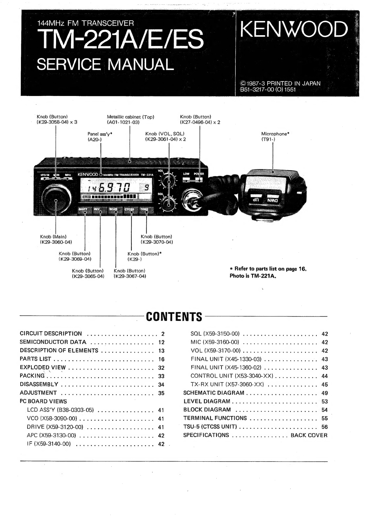
Kenwood TM-221A User manual
Other Kenwood Transceiver manuals

Kenwood
Kenwood TH-235A User manual

Kenwood
Kenwood TR-9500 User manual

Kenwood
Kenwood TS-850S User manual

Kenwood
Kenwood TK-8102H User manual

Kenwood
Kenwood TK-2402V User manual

Kenwood
Kenwood FleetSync TK-790 User manual

Kenwood
Kenwood TS-700A User manual

Kenwood
Kenwood TM-732A User manual

Kenwood
Kenwood TS-820 User manual

Kenwood
Kenwood TK-2217 User manual

Kenwood
Kenwood TK-2202 User manual

Kenwood
Kenwood TK-3202 User manual

Kenwood
Kenwood TK-3160 User manual

Kenwood
Kenwood TK-5210 User manual

Kenwood
Kenwood TM-201A User manual

Kenwood
Kenwood TS-780 User manual

Kenwood
Kenwood TK-380 User manual

Kenwood
Kenwood TH-K4AT User manual

Kenwood
Kenwood NX-1800HNU User manual

Kenwood
Kenwood NEXEDGE NX-411 User manual