Skanti TRP 5000 User manual

TRP 5000
INSTRUCTION MANUAL
CONTENTS
Page
1. INTRODUCTION
1 - 1
2. OPERATING INSTRUCTIONS
2.1 Distress Operation on 2182 kHz
2.2 Tuning to 2182 kHz
2.3 Tuning to a Frequency Other than 2182 kHz
2.4 Operating Controls and their Functions
2.5 Filter Cleaning
2 –1
2 –1
2 –1
2 –2
2 –2
2 –2
2 –5
3. INSTALLATION
3.1 Types of Installations
3.2 Removal of Units
3.3 Mounting the Cabinet
3.4 Connection to the Permanent Installation
3.5 Earth Connections
3.6 Antennas
3.7 Remote Speaker
3.8 Transmitter-on Indication
3.9 Replacement of Power Pack
3.10 Optional Terminal Strips
3.11 Programming of MEMOFIY /238\ , General
3.12 Ordering Programmed PROM’s
3.13 Instruction for use of PROGRAMMING IINIT /241\
3.14 Adjustment of Antenna Tuning
3 –1
3 –1
3 –1
3 –1
3 –1
3 –2
3 –3
3 –5
3 –5
3 –5
3 –5
3 –7
3 –8
3 –14
3 –17
4. TECHNICAL DATA
4 –1
5. TECHNICAL DESCRIPTION
5.1 Mechanical
5.2 Circuit Description General
5.3 Circuit Summary, Exciter E 5000
5.4 Circuit Description, Exciter E 5000
5.5 Circuit Summary, Transmitter Power Amplifier T 5000
5.6 Circuit Description, Transmitter Power Amplifier T 5000
5.7 Circuit Summary, 24 V DO Power Pack P 5000
5.8 Circuit Description, 24 V DC Power Pack P 5000
5.9 Circuit Summary, AC Power Pack P5001
5.10 Circuit Description, AC Power Pack P 5001
5 –1
5 –1
5 –1
5 –2
5 –3
5 –10
5 –10
5 –11
5 –12
5 –14
5 –14

TRP 5000
INSTRUCTION MANUAL
CONTENTS
Page
6. SIMPLE SERVICE
6.1 Incorrect Operation
6.2 Battery
6.3 Checking the Antenna Tuning
6.4 Using the CHECK SWITCH
6.5 Replacement of Fuses
6 - 1
6 - 1
6 –1
6 –1
6 –1
6 - 2
7. REPAIR AND ALIGNMENT
7.1 Introduction
7.2 Cross Slot Screws
7.3 Locating Sub-units and Components
7.4 Locating Faults
7.5 Test Points
7.6 AC Voltages
7.7 DC Voltages
7.8 Replacement of Valves
7.9 Adjustments
7.10 /232\ Realignment of 1.4 MHz EXCITER
7.11 /233\ Realignment of RF TRANSLATOFT
7.12 /234\ Realignment of CONTROL CIRCUIT AND TONE
GENERATORS
7.13 /235\ Realignment of HARMONIC GENERATOR
7.14 /236\ Realignment of VCO
7.15 /240\ Realignment of MASTER OSCILLATOR
7.16 /251\ Realignment of DRIVER
7.17 /254\ Realignment of VOLTAGE REGULATORS
7 - 1
7 - 1
7 - 1
7 - 1
7 - 1
7 - 1
7 - 1
7 –2
7 –2
7 –3
7 –4
7 –5
7 –8
7 –9
7 –10
7 –10
7 –10
7 –10
8. PARTS LISTS AND CIRCUIT DIAGRAMS
8.1 Numbering
8.2 Switches
8.3 Terminals
8.4 Voltages
8.5 Test Points
8.6 Symbol Explanation
8.7 Abbreviations
8.8 Parts Lists
8.8 Block diagram, Exciter E 5000
8 - 1
8 - 1
8 - 1
8 - 1
8 - 1
8 - 2
8 - 2
8 - 5
8 - 60

LIST OF ILLUSTRATIONS
Page
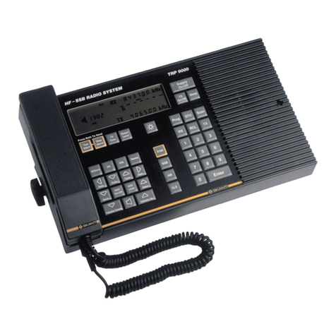
Front panel and operating controls
PROM-types which can be installed in the MEMORY /238\
Drilling plan for mounting of TRP 5000
TRP 5000 cabinet, standard version
TRP 5000 cabinet, optional terminal strips installed
Terminal Strip A
Terminal Strip B
Terminal Strip C
Terminal Strip D
Installation of external antenna relay
Initial tab settings, Lower GT band
Initial tab settings, Upper CT band
Initial tab settings, 4-6 MHz bands
Initial tab settings, 8-16 MHz bands
Initial tab settings, 22-25 MHz bands
T 5000 Tuning Chart
Programming Work Sheet
Function table for 234IC5
Function table for 235IC4
Location of circuit boards, E 5000
Location of circuit boards, T 5000
Location of circuit boards, P 5000
Location of circuit boards, P 5001
1-2
3-6
3-20
3-21
3-22
3-23
3-24
3-25
3-26
3-27
3-28
3-29
3-30
3-31
3-32
3-33
3-34
7-11
7-12
8-56
8-57
8-58
8-59

LIST OF DIAGRAMS
Page
Block Diagram, Exciter E 5000
Block Diagram, Transmitter Power Amplifier, T 5000
Block Diagram, 24 V DC Power Pack, P 5000
Block Diagram, AC Power Pack, P 5001
Keying circuit, simplified diagram, 24 V DC
Keying circuit, simplified diagram, AC
/230\ E 5000 Wiring Diagram, /231\ Motherboard
/232\ 1.4 MHz Exciter
/233\ RF Translator
/234\ Control Circuit and Tone Generators
/235\ Harmonic Generator
/236\ VCO
/237\ Frequency Dividers
/238\ Memory
/239\ Display and Keyboard
/240\ Master Oscillator
/241 \Programming Unit
/250\ T 5000 Wiring diagram
/251\ Driver
1252\ Meter Circuit
1253\ Band indicator
/254\ Voltage Regulators
/260\ P 5000 24 V DC Power Pack Wiring Diagram
/261\ Converter-driver, LT-rectifiers and Stabilisers
/262\ HT-rectifiers and Base Keying Circuit
/262\ Driver and Grid Voltage Stabilisers
/264\ input Voltage Sensor
/265\ P 5001 AC Power Pack Wiring Diagram
/266\ LT-stabilisers
/267\ HT-rectifiers
/268\ Driver and Grid Voltage Stabilisers
TRP 5000 Cabinet Wiring
Terminal Strip A
8-60
8-61
8-62
8-63
8-64
8-65
8-67
8-69
8-71
8-73
8-75
8-77
8-79
8-81
8-83
8-85
8-87
8-89
8-91
8-93
8-95
8-97
8-99
8-101
8-103
8-105
8-107
8-109
8-111
8-113
8-115
8-116
8-117

1. Introduction
1.1 The TRP 5000 is a single side band radiotelephone transmitter receiver
combination for duplex, semi-duplex and simplex telephone traffic in
the 1.6-4 MHz coastal telephone band and in the maritime mobile short
wave bands between 4 and 27.5 MHz. In addition the TRP 5000 provides
facilities for radiotelegraph and telex transmission and reception
The TRP 5000 is composed of the T5000transmitter power amplifier, the P
5000 (24 V DC) or the P 5001 (AC) power pack, the E 5000 exciter and
the R 5000 receiver. This instruction manual describes the Transmitter
Power Amplifier, the Exciter and the Power Packs, while the Receiver is
covered in a separate manual.
The transmitter is fully synthesised and provides keyboard selection of
up to 256 pre-programmed frequencies, which can be freely distributed
in the maritime frequency bands.
Silicon transistors and integrated circuits are used throughout except
for the transmitter power amplifier stage. These features in
conjunction with the fact that no crystal ovens are used enable the
transmitter to be ready for operation within 30 seconds after being
switched on.
The cabinet is a sturdy 19-inch rack construction containing all
necessary inter- connections.
Because we are constant processing the experience gained during the
production and operation of our equipment, it is possible for minor
modifications to occur relative to the information given in this
instruction manual. Wherever practicable, however, any corrections will
be listed on a correction sheet at the back of the front cover of this
manual.

1 - 1

1 - 2

2. Operating Instructions
2.1 Distress Operation on,2182 kHz
Set controls as fellows:
A SUPPLY to TRANSMIT
B C BANDs to 2182 kHz
D VOLUME clockwise
E SENSITIVITY fully clockwise
F MODE to TRANSMIT ALARM
G Press and release ALARM START
The alarm signal is now transmitted for approx. 45 seconds and may be
monitored in the handset earpiece. When the alarm signal ceases depress
handset key and, speaking clearly into microphone, transmit distress
message.
If it is required to repeat the alarm signal transmission, it Is only
necessary to press and release the ALARM START push button again.
An alarm signal transmission may be interrupted at any time by turning the
MODE switch to A3H.
NOTE: In the TRANSMIT ALARM mode on 2182 kHz the power output of the
transmitter is automatically set to FULL POWER SIMPLEX independent of
the setting of the POWER switch.
2.2 Tuning to 2182 kHz
1. Set SUPPLY switch to TRANSMIT.
30 seconds after switching on the transmitter is ready for operation.
2. Set BAND switch to 2182 kHz.
The band-indicator lamp will show constant light indicatingthat2182
kHz is selected. The FREQUENCY NO display will extinguish.
3. Press TUNE button and adjust TUNING control for maximum deflection on
ANTENNA CURRENT meter.
The tuning range on 2182 kHz is reduced so that power is transmitted
even when the TUNIN-G control is not adjusted.
The transmitter is now ready for operation.
NOTE: The type of service used on 2182 kHz is A3H, simplex. This mode is
automatically selected when the BAND switch is set to 2182 kHz, and the
MODE switch can therefore be set to any position except TESTALARM. The
equipment will also work in the simplex mode even if the POWER switch is
in a DUPLEX position.

2 - 1

2.3 Tuning to a Frequency Other than 2182 kHz
1. Set SUPPLY switch to TRANSMIT.
30 seconds after switching on the transmitter is ready for operation,
2. Set BAND switch to any band except 2182 kHz
3. Turn DIMMER control fully clockwise
4. If FREQUENCY NO display does not show zero, clear display using C key
of keyboard.
5. Look up desired frequency in frequency chart and read Frequency -No
6. Key Frequency No. into keyboard. The selected Frequency No. will be
displayed.
7. Set BAND switch to position indicated by flashing band indicator lamp.
If no flashing occurs the BAND switch is already correctly set.
8. Press TUNE button and adjust TUNING control for maximum deflection on
ANTENNA CURRENT meter.
9 Select desired type of service with MODE and POWER switches.
Transmitter is now ready for operation
NOTE: Transmission is inhibited if the mode setting does not correspond
with the frequency selected. On radiotelephone frequencies the transmitter
can be keyed only in the modes A3A, A3J, A3H, and TRANSMIT ALARM. On
wireless telegram frequencies the transmitter can be keyed only in the
modes Al, A2H, and Fl.
2.4 Operating Controls and their Functions
2.4.1 The SUPPLY switch has four positions
OFF Receiver and transmitter are switched off.
REGEIVE ONLY Power Pack is started up and supplies power to Receiver
(and grid bias to transmitter output valves). Remote
speaker of receiver is connected to receiver output.
STAND BY Power Pack supplies power to Receiver, Exciter, band
indicator, and filaments of transmitter output valves.
Remote speaker of receiver is connected to receiver
output.
TRANSMIT Transmitter can be keyed. Remote speaker of receiver is
disconnected.
NOTE:A built-in delay circuit protects the output valves of the
transmitter from being keyed for the first 30 sec. after switching to
STAND BY or TRANSMIT.
2 - 2

2.4.2. The POWER switch has six positions
LOW POWER
SIMPLEX
Transmitter is keyed from handset key, morse key, or
telex equipment dependent on mode of operation. Receiver
is muted while transmitting.
Transmitter can be driven to approx. 1/20 Of full output
power.
MEDIUM POWER
SIMPLEX
As above, but transmitter can be driven to approx. 1/4 of
full output power.
FULL POWER
SIMPLEX
As above, but transmitter can be driven to full power.
FULL POWER
DUPLEX
Transmitter is keyed constantly in the Fl, A3A, A3J, A3H
and TRANSMIT ALARM modes (provided the selected frequency
is in accordance with the mode setting). Receiver is on
but built-in speaker is disconnected.
In the A2H and Al modes the operation is simplex
independent of the setting of the POWER switch.
Transmitter can be driven to full output power.
MEDIUM POWER
DUPLEX
As above, but transmitter can be driven to approx. 1/4 of
full output power.
LOW POWER
DUPLEX
As above, but transmitter can be driven to approx. 1/20
of full output power.
NOTE: With the BAND switch set to 2182 kHz, simplex is automatically selected,
independent of the POWER switch setting, and if at the same time the MODE switch
is set to TRANSMITALARM, the transmitter is automatically set to full power.
The MODE switch has eight positions
A2H
Transmission of modulated radiotelegraphy. Only the
morse key input is open. The transmitter can only be
keyed if a telegraphy frequency is selected.
Al
Transmission of un-modulated radiotelegraphy. Only the
morse key input is open. The transmitter can only be
keyed if a telegraphy frequency is selected.
F1
Transmission of telex. Only the telex inputs are open.
Trans- mission is only possible if a telegraphy
frequency is selected.
TEST ALARM
The built-in two tone alarm generator is connected to
the receiver AF amplifier. Transmitter cannot be keyed.
A3A
Transmission of single-side band signal with reduced
carrier. Transmission is only possible if a radio
telephony frequency is selected. The transmitter can be
keyed from the hand set key or by setting the POWER
switch to DUPLEX.
A3J
As above, but carrier suppressed
A3H
As above, but full carrier.
TRANSMIT ALARM
The two-tone alarm generator is connected to the
receiver AF amplifier and the alarm generator is ready
for transmission of an alarm signal. The mode is A3H as
above.

2 - 3

2.4.4 The ALARM START push-button is used to start the alarm generator after
the MODE switch has been turned to the TRANSMIT ALARM position. The
push-button is depressed and released and the alarm signal will be
transmitted for approx. 45 seconds.
The push-button is also used for starting the alarm generator in the
TEST ALARM position.
2.4.5 The KEYBOARD is used for frequency selection. It controls the frequency
memory. The programmed frequencies are listed in the frequency chart.
Each frequency is supplied with a number and this number is keyed into
the keyboard. The frequency number selected is displayed on the
FREQUENCY NO display.
The display is cleared by using the C-key, which resets the display to
zero.
The display extinguishes when the BAND switch is set to 2182 kHz, but
keyboard entry is still possible and the display will show the selected
Frequency No. when the BAND switch is turned away from 2182 kHz.
If an un-programmed Frequency No is selected, the display will start to
flash, indicating that transmission is not possible.
2.4.6 The DIMMER controls the intensity of the FREQUENCY NO display.
2.4.7 The TUNING control is used for tuning the antenna circuit to maximum
antenna current indicated on the ANTENNA CURRENT meter.
2.4.8 The BAND switch has 16 positions:
2182 kHz The FREQUENCY NO display is extinguished and the band-
indicator lamp shows constant light indicating that 2182 kHz is
selected. The range of the TUNING control is reduced. The A3H,
simplex mode is automatically selected.
Bands A to H cover the coastal telephone band 1.6 to 4 MHz.
The 4 MHz, 6 MHz, 8 MHz, 12 MHz, 16 MHz, 22 MHz, and 25 MHz positions
cover the maritime short-wave bands.
A band indicator lamp at each position shows by flashing light where to
set the BAND switch in accordance with the Frequency No selected. The
light will extinguish when the BAND switch is set at the correct
position.
2.4.9 The TUNE push-button is used when tuning the antenna circuit. The
transmitter is keyed and a tune signal is generated. During tuning, the
receiver is muted.

2 –4

2.4.10 The CHECK SWITCH is not normally operative. Pulling the switch knob out
will switch the ANTENNA CURRENT meter to read the voltage or current
selected with the switch. When released, the knob will return to its
original position.
The switch has eight positions:
LEVEL Check of anode AG voltage swing
VA Check of anode DC voltage
Vs1 Check of screen grid voltage of valve no. 1
Vs2 Check of screen grid voltage of valve no. 2
VG Check of grid bias
I1 Check of cathode current of valve no. 1
I2 Check of cathode current of valve no. 2
VD Check of supply voltage to driver amplifier.
2.5 Filter Cleaning
The air filter on the transmitter power amplifier front panel should be
cleaned periodically. The filter element is easily removed without the
use of tools. Wash in warm water and dry thoroughly.

2 - 5

Installation
Correct installation of the equipment is important for maximum performance
and reliability. Antennas and earth connections must be installed with the
greatest care, especially where duplex telephony is desired.
3.1 Types of Installation
The TRP 5000 radiotelephone may be powered from either a
24V battery or from 110/115/120/220/230/240V-AC mains.
The TRP 5000 is composed of the following units:
For 24V battery operation:
Type T 5000 transmitter power amplifier
Type P 5000 power pack
Type E 5000 / E5001 exciter
Type R 5000 / R5001 receiver
For AC mains operation (single-phase or two-phase):
Type T 5000 transmitter power amplifier
Type P 5001 power pack
Type E 5000 / E5001 exciter
Type R 5000 / R5001 receiver
The units are connected together in the TRP5000 cabinet in which also the
connections to the permanent installation are made.
3.2 Removal of units
After removal of the front-panel screws, the units may be pulled out as
far as the built-in stops permit. The cables may be unplugged and the
individual units removed entirely from the cabinet after having released
the stop latches. This is done by pushing the unit slightly back into the
cabinet (approx. 10 mm) and pressing the two nylon knobs of the latches at
the sides of the unit while pulling the unit out.
For ease of removal of the units start with the lowest and proceed
upwards. The reverse order is used when refitting the units.
3.3 Mounting the Cabinet
The cabinet is supplied with shock absorbers. The drawing on page3-
20showsthe drilling plan for the necessary holes.
3.4 Connection to the Permanent Installation
Check that the correct power pack is installed in the equipment and, in
case of AC operation, set f or the correct mains voltage. The drawing of
Terminal strip A on page 3-23 shows the marking of the terminals to be
used for the installation. Necessary cable cross sections are also
indicated. All cables except the transmitter antenna and earth leads are
brought through the cut out in the cabinet rear wall in a loop that is
large enough to take up any play between the equipment and the bulkhead.
3 –1

A mains switch and fuses are to be provided in the supply leads. External
fuse ratings are listed in Table 3.1.
Power Pack
Supply Voltage
External Fuses
P 5000
24V
DC
5OA
P 5001
110V
115V
120V
50-60
Hz
20A
P 5001
220V
230V
240V
50-60
Hz
15A
Table 3.1
3.4.1 Supply Voltage Changing in P 5001 (AC operation) :
Voltage Changing in the P 5001 power pack is carried out by unsoldering
the connections to and between the terminals of the two transformers
265 TI and 265 T2.
The necessary connections are shown on the diagram of P 5001.
When changing voltage it is also necessary to replace the fuse in the
power pack input lead. Fuse rating is given on the P 5001 diagram.
3.5 Earth Connections
As the transmitter earth connection is always a part of the total
antenna system, it is of the utmost importance that the earth
connection is constructed to have the smallest possible RF-impedance.
Losses in the earth connection will result in a decrease in radiated
power which means that the range of the transmitter will be reduced. A
poor earth connection will further impede or even make duplex
communication impossible.
3.5.1 Transmitter Earth Terminal:
The transmitter earth terminal is located on the top of the cabinet.
3.5.1.1 Steel Ships:
From the transmitter earth terminal a 100x0.5 mm copper strap is run
un-interrupted to two 1/2" bolts welded to the hull as close to the
equipment as possible

3 –2

3.5.1.2 Wooden Ships:
From the transmitter earth terminal a 100x0.5 mm copper strap is run,
preferably uninterrupted, to an earth bolt welded to an earth plate
having a minimum area of 1 m2 mounted under the water line. Should it,
however, be necessary to break the copper strap, for example to pass
through a deck, two 1/2" bolts should be used for this feed through.
The copper strap should then be continued below deck, after connection
to the same two bolts.
The copper strap must not be passed through iron pipes and should be
kept a minimum distance of 0.5 m from iron parts of some extent. If
this minimum distance cannot be kept the copper strap must be
effectively connected to these parts using a strap having the same
dimensions.
On wooden ships having a superstructure of metal, this superstructure
should also be effectively connected to the copper strap.
5.2.2 Receiver Earth Terminal
The receiver earth terminal is located on terminal strip A at the
cabinet rear wall
3.5.2.1 Steel Ships
A flexible 2.5 MM2earth wire is run from the receiver earth terminal to
a separate/2" earth bolt welded to the hull as close to the equipment
as possible. This earth bolt must not be used for earthing other
equipment, and the receiver earth wire shall be as far as possible from
the transmitter copper strap.
3.5.2.2 Wooden Ships
A flexible 2.5 MM2 earth wire is run from the receiver earth terminal
directly to the transmitter earth bolt on the earth plate. The earth
wire should be run a minimum distance of 0.5 m from the transmitter
copper strap.
3.5.3 Other Cables
Other cables should be placed as far away as possible from the
transmitter and receiver earth leads and under no circumstances
parallel with the transmitter copper strap closer than 0.7 meter and,
for the receiver earth lead, closer than 0.2 meter.
3.5.4 Earthing the Battery
RF earth connections will cause neither battery nor mains leads to be
connected to the hull. If it is desired to connect the battery to the
hull, it is important to make the connection right at the battery,
never in the transmitter. In cases where the installation is carried
out so as to include the facility for charging during operation through
a dropping resistor from a balanced ship's mains (110/220V DC), the
battery must not be earthed.
3.6 Antennas
In order to minimise duplex noise, the transmitting and receiving
antennas should be kept as far away from each other as possible. Stays,
wires, steel masts etc. should either be earthed effectively or
insulated.
Table of contents
Other Skanti Transceiver manuals