Kessel 80888 User manual

MONTAGEHINWEIS
Ersatzteil Sonde + Ada ter (Art. Nr. 80888)
Für alle Staufix Premium Systeme und Ecolift für folgende Schaltgeräte:
80073, 28073, 80071, 28071, 21071 und Ersatz Sonden 80085, 80086, 80087, 80088
Sach-Nr. 010-880 Stand 2013/03
Page 1
Page 4
Page 7
Pagina 10
Pagina 13
Strona 16
Beachten Sie die Sicherheitshinweise und weitere Beschreibung in den zugehörigen EBAs.
• Für den Ersatz der Pumpensonde ist der rote Adapter (der Rote
Adapter entspricht der alten Sonde 80086!) richtig aufzustecken
(Bajonettverschluss, 1/4 Umdrehung gegen den Uhrzeigersinn) und
den roten Aufkleber am Sondenkabel in Steckernähe anbringen –
siehe Bild 1-3.
• Für den Ersatz der Motorsonde ist der schwarze Adapter richtig auf-
zustecken – siehe Bild 4-6.
• Diese Erhöhungen verhindern
einen Fehlverbau und müssen
beim Verschrauben am Rück-
stausystem nach oben zeigen.
①②③④
Lieferumfang
Wenn bauseits erforderlich (z. B. Kabelleerrohr, Länge ändern, etc.)
Schwarze
Verschraubung
abschrauben
Stecker abziehen Rückstände entfernen
Kabel bis Anschlag
einführen
Montagehinweis Adapter:
Alte Kontaktstellen entfer-
nen und neu abisolieren
Gültig ab Baujahr 01/2011
⑤⑥
Fortsetzung Seite 2
010-880_6SPRACHIG_DIN_A5.QXP_ ayout 1 05.03.13 13:38 Seite 1

2
Kabel Steckerposition
Blau 1
Weiß 2
Schwarz 3
Gültig bis Baujahr 1996
Belegung der Adern am Stecker:
Blauer Draht auf blaue Markierung, weißer Draht auf weiße Mar-
kierung, schwarzer Draht auf schwarze Markierung.
Gültig von Baujahr 1996-2010
Wenn bauseits erforderlich (z. B. für Kabelleerrohr, Länge ändern)
Adern gemäß
Belegung einklemmen
Überstehendes
Kabel bündig
abschneiden
Schwarze Ver-
schraubung
aufschrauben
Zubehör:
Verlängerungset für Sonde (10 m)
Art. Nr. 80889
ACHTUNG: Anschluss Sonde nur bei Schaltgeräten bis Bj. 1996
rote und grüne Platine
Pfeil zu Nase
Fortsetzung Seite 3
010-880_6SPRACHIG_DIN_A5.QXP_ ayout 1 05.03.13 13:38 Seite 2

3
①Gültig ab 01/2011
Adapter für alle Pumpensonden
Gültig bis 12/2010
Adapter für alle Sonden Staufix®FKA und Pumpfix®F
mit Nennweite DN 100
②Gültig ab 01/2011
Adapter für alle Motorsonden
③Gültig bis 12/2010
Adapter für alle Sonden Staufix®FKA und Pumpfix®F
mit Nennweite DN 125 und DN 150
• Diese Erhöhungen verhindern einen Fehlverbau
und müssen beim Verschrauben am Rückstau-
system nach oben zeigen.
① ② ③
Montagehinweis Adapter:
Allgemein: Die Adapter dienen zur Befestigung der neuen Sonden ohne Befestigungslaschen.
• Hier ist auf ordentlichen Sitz des O-Ringes
zu achten.
Verwendung der einzelnen Addapter abhängig vom Sondentyp bzw.
vom Rückstausystem (siehe 1-3)
010-880_6SPRACHIG_DIN_A5.QXP_ ayout 1 05.03.13 13:38 Seite 3

4
INSTALLATION INSTRUCTION
Re lacement Probe + Ada tor (Art.No. 80888)
For all Staufix Premium and Ecolift backwater valves / pumps for the following control units
80073, 28073, 80071, 28071, 21071
and replacement probe 80085, 80086, 80087, 80088
lease follow the safety and product information contained in the Install. and User's manual
• When replacing the pump probe the red plastic adaptor must be pro-
perly connected (attached and turn a quarter turn counter clockwise).
Also take the small red sticker and stick it to the probe cable near the
connection plug (see photos 1-3).
• When replacing the motor probe the black plastic adaptor must be
connected (see photos 4-6)
• These raised tips prevent
the probe from being con-
nected improperly and must
always point upward.
①②③④
Contents of delivery
If required on-site (ex. for conduit pipes, cable length changes, etc.)
Unscrew the
black connector.
Remove plug. Remove any residue.
Insert cables until they
contact back of plug.
Adaptor installation instructions:
Restrip cables.
Valid beginning Jan 2011
⑤⑥
Continued page 5
010-880_6SPRACHIG_DIN_A5.QXP_ ayout 1 05.03.13 13:38 Seite 4

5
Cable Jack
blue 1
white 2
black 3
Valid up to 1996
Cable description:
Blue cable on blue mark, white cable on white mark, black cable
on black mark
Valid from 1996 to 2010
If required on-site (for example for conduit pipes, cable length changes, etc.)
Connect cables to pro-
per position (see des-
cription to the right)
Cut off any cable
portions which are
sticking out
Re-screw the
black connector to
the plug
Accessories:
10 meter probe cable extension -
Article Number 80889
Attention: connection of probe on for control units up to 1996
Red and green circuit board
Arrow on plug
should match
triangular tip on
threads.
Continued page 6
010-880_6SPRACHIG_DIN_A5.QXP_ ayout 1 05.03.13 13:38 Seite 5

6
①For models January 2011 and newer
Adaptor for all pump optical sensors
For models up to December 2010
Adaptor for all Staufix FKA and Pumpfix F
optical sensors for DN 100 (OD 110 mm) models
②For models January 2011and newer
Adaptor for all motor optical sensors
③For models up to December 2010
Adaptor for all Staufix FKA and Pumpfix F optical sen-
sors for DN 125 (OD 125 mm) and DN 150 (OD 160
mm) models.
Must be used in combination with the red adaptor
(adaptor ① is inserted into the top of adaptor ③).
• The raised edge on the adaptors are to assure the adaptor ist installed properly
and should always be pointing up.
① ② ③
Installation note adaptor:
General: The adaptors are used to fasten the new Probes without mounting brackets.
Use each adaptor depending on probe type and the backwater system (see 1-3)
010-880_6SPRACHIG_DIN_A5.QXP_ ayout 1 05.03.13 13:38 Seite 6

7
AVIS DE MONTAGE
Pièce de rechange sonde + ada tateur (Réf. n° 80888)
Approprié à tous les systèmes Staufix Premium et Ecolift pour les boîtiers de commande suivants :
80073, 28073, 80071, 28071, 21071 et les sondes de rechange 80085, 80086, 80087, 80088
Observez les consignes de sécurité et autres descriptions données dans les instructions de
montage respectives.
• Emboîtez l'adaptateur rouge (l'adaptateur rouge correspond à l'an-
cienne sonde 80086 !) correctement (emboîtement à baïonnette, 1/4
de tour contre le sens des aiguilles d'une montre) et fixez l'autocollant
rouge sur le câble de la sonde à proximité directe de la fiche si vous
devez remplacer la sonde de la pompe – voir figure 1-3
• Emboîtez l'adaptateur noir correctement si vous devez remplacer la
sonde du moteur – voir figure 4-6
• Ces compensations de hauteur
préviennent le risque d'une pose
erronée et doivent pointer vers le
haut après le vissage sur le sys-
tème de protection anti-retour.
①②③④
Fournitures
Si nécessaire sur site (p. ex. pour conduit de câbles, la modific. de la longueur etc.)
Dévissez le
vissage noir
Retirez la fiche Éliminez les dépôts
Introduisez le câble
jusqu'à la butée
Avis de montage de l'adaptateur :
Enlevez les vieux contacts
et réisolez
Valable à partir de l'année de construction 01/2011
⑤⑥
Suite à la page 8
010-880_6SPRACHIG_DIN_A5.QXP_ ayout 1 05.03.13 13:38 Seite 7

8
Câble osition sur la fiche
Bleu 1
Blanc 2
Noir 3
Valable jusqu'à l'année de construction 1996
Occupation des conducteurs de la fiche :
conducteur bleu sur le repère bleu, conducteur blanc sur le re-
père blanc, conducteur noir sur le repère noirwarze Markierung.
Valable à partir de l'année de construction 1996-2010
Si nécessaire sur site (p. ex. pour un conduit de câbles, la modification de la longueur etc.)
Serrez les conducteurs
conformément à l'occu-
pation (voir à droite)
Coupez le câble
excédentaire à
franc-bord
Vissez le vissage
noir
Accessoire :
kit de rallonge pour sonde
(10 mètres) Réf. n° 80889
ATTENTION : raccordement de la sonde uniquement pour boîtiers de
commande jusqu'à l'année de construction 1996.
platine rouge et verte
Flèche vers le
tenon
Suite à la page 9
010-880_6SPRACHIG_DIN_A5.QXP_ ayout 1 05.03.13 13:38 Seite 8

9
①Valable à partir de 01/2011
Adaptateur pour toutes les sondes de pompe
Valable jusqu'à 12/2010
Adaptateur pour toutes les sondes Staufix FKA et
Pumpfix F d'un diamètre nominal DN 100
②Valable à partir de 01/2011
Adaptateur pour toutes les sondes du moteur
③Valable jusqu'à 12/2010
Adaptateur pour toutes les sondes Staufix FKA et
Pumpfix F d'un diamètre nominal DN 125 et DN 150
• Ces compensations de hauteur préviennent le
risque d'une pose erronée et doivent pointer
vers le haut après le vissage sur le système de
protection anti-retour.
① ② ③
Avis de montage de l'adaptateur :
En général : les adaptateurs servent à la fixation des nouvelles sondes sans languettes de fixation.
• Apportez une importance particulière au lo-
gement correct du joint torique.
Utilisation des différents ada tateurs en fonction du ty e de sonde et / ou du système de ro-
tection anti-retour (voir 1-3)
010-880_6SPRACHIG_DIN_A5.QXP_ ayout 1 05.03.13 13:38 Seite 9

10
ISTRUZIONI ER IL MONTAGGIO
Pezzo di ricambio sonda + adattatore (n. art. 80888)
Per tutti i sistemi Staufix Premium ed Ecolift per le seguenti centraline:
80073, 28073, 80071, 28071, 21071 e sonde di ricambio 80085, 80086, 80087, 80088
Rispettare le avvertenze sulla sicurezza e lʼulteriore descrizione nelle relative istruzioni per il
montaggio.
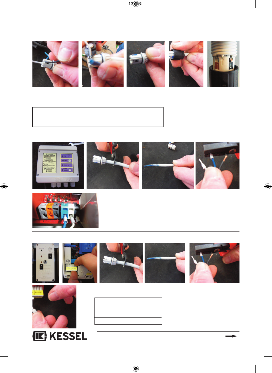
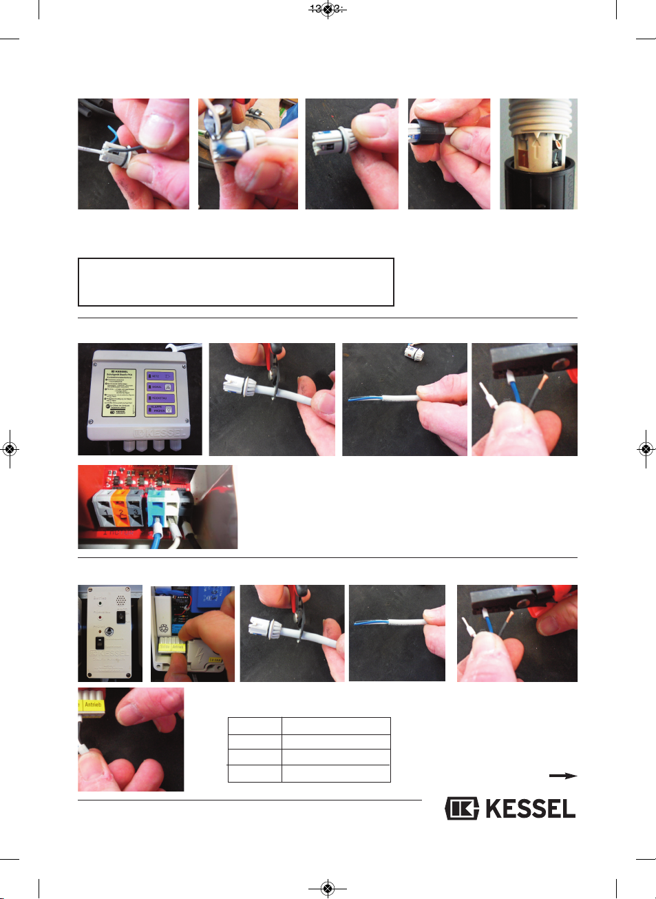
• Per la sostituzione della sonda della pompa applicare correttamente
l’adattatore rosso (che corrisponde alla vecchia sonda 80086!) (chiu-
sura a baionetta, ¼ di giro in senso antiorario) e l’adesivo rosso sul
cavo della sonda vicino alla spina – vedi illustrazione 1-3
• Per la sostituzione della sonda del motore applicare correttamente
l’adattatore nero – vedi illustrazione 4-6
• Questi rialzi impediscono un
montaggio errato e durante
l’avvitamento sul sistema an-
tiriflusso devono essere rivolti
verso l’alto.
①②③④
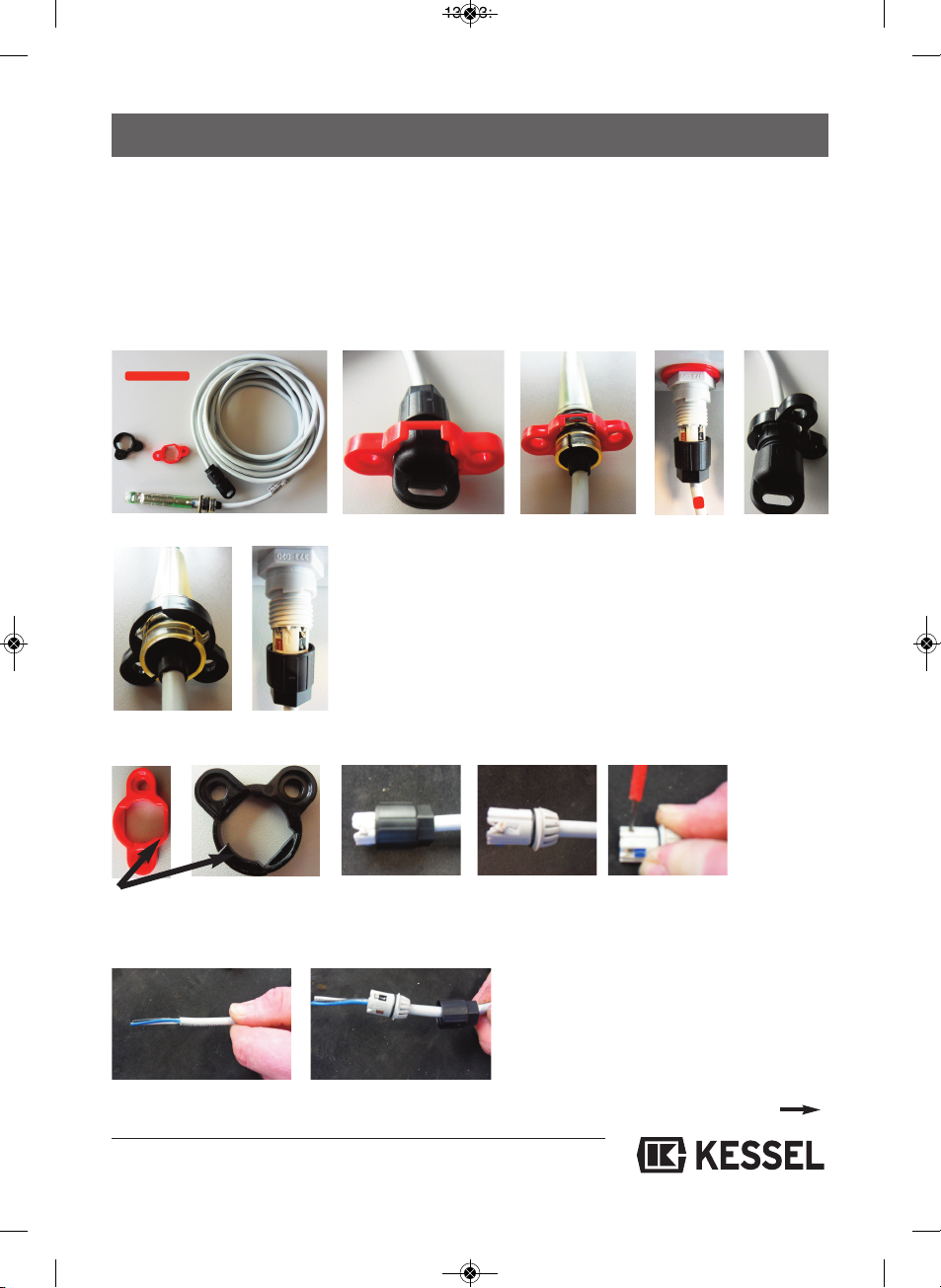
Volume della fornitura
Se necessario a cura del committente (p.es. per tubo vuoto per
cavi, modificare la lunghezza, ecc.)
Svitare il
raccordo a vite
nero
Staccare la spina Eliminare i residui
Introdurre il cavo fino
all’arresto
Istruzioni per il montaggio
dellʼadattatore:
Eliminare i punti di contatto
vecchi e rispelare
Valido dallʼanno di costruzione 01/2011
⑤⑥
Continua a pagina 11
010-880_6SPRACHIG_DIN_A5.QXP_ ayout 1 05.03.13 13:38 Seite 10

11
Cavo osizione spina
blu 1
bianco 2
nero 3
Valido dallʼanno di costruzione 1996
Occupazione dei fili sulla spina:
filo blu sul contrassegno blu, filo bianco sul contrassegno bianco,
filo nero sul contrassegno nero.
Valido dallʼanno di costruzione 1996-2010
Se necessario a cura del committente (p.es. per tubo vuoto per cavi, modificare la lunghezza)
Collegare i fili secondo
l’occupazione (vedi
destra)
Tagliare a paro il
cavo sporgente
Avvitare il rac-
cordo a vite nero
Accessori:
set di prolungamento per sonda
(10 m) n. art. 80889
ATTENZIONE : collegamento sonda solo per centraline fino all’anno di
costruzione 1996
scheda rossa e verde
Freccia verso il
nasello
Continua a pagina 12
010-880_6SPRACHIG_DIN_A5.QXP_ ayout 1 05.03.13 13:38 Seite 11

12
① Valido dallo 01/2011
Adattatore per tutte le sonde delle pompe
Valido fino al 12/2012
Adattatore per tutte le sonde Staufix FKA e Pumpfix F
con diametro nominale DN 100
②Valido dallo 01/2011
Adattatore per tutte le sonde dei motori
③Valido fino al 12/2010
Adattatore per tutte le sonde Staufix FKA e Pumpfix F
Con diametro nominale DN 125 e DN 150
• Questi rialzi impediscono un montaggio
errato e durante l’avvitamento sul sis-
tema antiriflusso devono essere rivolti
verso l’alto.
① ② ③
Istruzioni per il montaggio dellʼadattatore:
In generale: gli adattatori servono al fissaggio senza linguette delle nuove sonde.
• Qui si deve assicurare un posizionamento
corretto della guarnizione OR.
Uso dei singoli adattatori secondo tipo di sonda o sistema antiriflusso (vedi 1-3)
010-880_6SPRACHIG_DIN_A5.QXP_ ayout 1 05.03.13 13:38 Seite 12

13
MONTAGE-INSTRUCTIE
Onderdeel sonde en ada ter (art.nr. 80888)
Voor alle Staufix Premium systemen en Ecolift voor de volgende schakelapparaten: 80073, 28073,
80071, 28071, 21071 en reservesonden 80085, 80086, 80087, 800888
Neem de veiligheidsinstructies en overige omschrijvingen in de bijbehorende EBAs in acht.
• Om de pompsonde te vervangen moet de rode adapter (de rode
adapter komt overeen met de oude sonde 80086!) correct worden
ingestoken (bajonetsluiting, 1/4 omdraaiing tegen de wijzers van de
klok in) en moet de rode sticker op de sondekabel in de buurt van de
stekker worden aangebracht – zie afbeelding 1-3.
• Om de motorsonde te vervangen moet de zwarte adapter correct
worden ingestoken – zie afbeelding 4-6.
• Deze verhogingen voorkomen
foutieve installatie en moeten
bij het vastschroeven aan het
opstuwingssysteem aan de
bovenkant zitten.
①②③④
Leveringsprogramma
Wanneer op locatie noodzakelijk (bv. voor lege kabelbuis, lengte
veranderen, enz.)
Zwarte schroef-
koppeling
afschroeven
Stekker uittrekken Residuen verwijderen
Kabel tot aanslag inbrengen
Montage-instructie adapter:
Oude contactpunten ver-
wijderen en opnieuw
isoleren
Geldig vanaf bouwjaar 01/2011
⑤⑥
Voortzetting pagina 14
010-880_6SPRACHIG_DIN_A5.QXP_ ayout 1 05.03.13 13:38 Seite 13

14
Kabel Stekkerpositie
Blauw 1
Wit 2
Zwart 3
Geldig tot bouwjaar 1996
Indeling van de leidingdraden bij de stekker:
blauwe draad op blauwe markering, witte draad op witte
markering, zwarte draad op zwarte markering.
Geldig vanaf bouwjaar 1996-2010
Wanneer op locatie noodzakelijk (bv. voor lege kabelbuis, lengte veranderen)
eidingdraden
conform indeling (zie
rechts) inklemmen
Uitstekende kabel
gelijk afsnijden
Zwarte schroef-
koppeling
opschroeven
Accessoires:
Verlengset voor sonde (10 m)
Art.nr. 80889
ATTENTIE: Aansluiting sonde uitsluitend bi schakelapparaten tot
bouw aar 1996
Rode en groene printplaat
Pijl naar uitstul-
ping
Voortzetting pagina 15
010-880_6SPRACHIG_DIN_A5.QXP_ ayout 1 05.03.13 13:38 Seite 14

15
①Geldig vanaf 01/2011
Adapter voor alle pompsonden
Geldig tot 12/2010
Adapter voor alle sonden Staufix FKA en Pumpfix F
met nominale doorlaat DN 100
②Geldig vanaf 01/2011
Adapter voor alle motorsonden
③Geldig tot 12/2010
Adapter voor alle sonden Staufix FKA en Pumpfix F
met nominale doorlaat DN 125 en DN 150
• Deze verhogingen voorkomen foutieve
installatie en moeten bij het vastschroe-
ven aan het opstuwingssysteem aan de
bovenkant zitten.
① ② ③
Montage adapter:
Algemeen: De adapters dienen ter bevestiging van de nieuwe sonden zonder bevestigingsstrips.
• Hier moet op goed zitten
van de O-ring worden gelet
Gebruik van de afzonderlijke adapters afhankelijk van het sondetype resp. van het opstuwingsys-
teem (zie 1-3)
010-880_6SPRACHIG_DIN_A5.QXP_ ayout 1 05.03.13 13:38 Seite 15

16
WSKAZÓWKA MONTAŻOWA
Cz
ęść
zamienna – Sonda + adapter (nr art. 80888)
Do wszystkic systemów Staufix Premium oraz Ecolift dla następującyc sterowników:
80073, 28073, 80071, 28071, 21071 i zamiennyc sond 80085, 80086, 80087, 80088
rzestrzegać wskazówek bezpieczeństwa oraz dalszych opisów w odpowiednich dokumentach
Instrukcja instalacji.
• W celu wymiany sondy pompy należy prawidłowo zatknąć czerwony
adapter (czerwony adapter odpowiada starej sondzie 80086!) (zamek
bagnetowy, 1/4 obrotu przeciwnie do ruc u wskazówek zegara) i
następnie czerwoną naklejkę znajdującą się na kablu sondy umieścić
w pobliżu wtyczki – patrz rysunek 1-3
• W celu zastosowania sondy silnikowej należy prawidłowo zatknąć
czarny adapter – patrz rysunek 4-6
• Te przewyższenia zapobiegają
błędnemu montażowi i w przy-
padku dokręcania do systemu
przeciwcofkowego muszą
wskazywać kierunek do góry.
①②③④
Jeśli jest to konieczne w miejscu montażu (np. dla rury kablowej,
zmiany długości itp.)
Odkręcić czarne
połączenia śru-
bowe
Odłączyć wtyczki Usunąć pozostałości
Kabel wprowadzić aż do
ogranicznika
Wskazówka montażowa dla
adaptera:
Usunąć wszystkie styki i
zaizolować je od nowa
Obowiązuje do roku produkcji 01/2011
⑤⑥
Kontynuacja – strona 17
Zakres dostawy
010-880_6SPRACHIG_DIN_A5.QXP_ ayout 1 05.03.13 13:38 Seite 16

17
Kabel ozycja wtyczki
Niebieski 1
Biały 2
Czarny 3
Obowiązuje do roku produkcji 1996
Obłożenie żył na wtyczce:
niebieski przewód na niebieskie zaznaczenie, biały przewód na
białe zaznaczenie, czarny przewód na czarne zaznaczenie.
Obowiązuje od roku produkcji 1996-2010
Jeśli jest to konieczne w miejscu montażu (np. dla rury kablowej, zmiany długości
Żyły wpiąć zgodnie z
ich obłożeniem (patrz
po prawej stronie)
Wystający kabel
równo odciąć
Nakręcić czarne
połączenie
śrubowe
Akcesoria:
zestaw przedłużania dla sondy
(10 m) Nr art. 80889
UWAGA! Przyłączenie sondy tylko w sterownikach do roku produkcji 1996
czerwona i zielona płytka
Strzałka do
noska
Kontynuacja – strona 18
010-880_6SPRACHIG_DIN_A5.QXP_ ayout 1 05.03.13 13:38 Seite 17

①Obowiązuje od 01/2011
Adapter do wszystkich sond do pomp
Obowiązuje do 12/2010
Adapter do wszystkich sond Staufix FKA i Pumpfix F
o szerokości znamionowej DN 100
②Obowiązuje od 01/2011
Adapter do wszystkich sond silnikowych
③Obowiązuje do 12/2010
Adapter do wszystkich sond Staufix FKA i Pumpfix F
o szerokości znamionowej DN 125 i DN 150
• Te przewyższenia zapobiegają
błędnemu montażowi i w przypadku
dokręcania do systemu przeciwcof-
kowego muszą wskazywać kieru-
nek do góry.
① ② ③
Wskazówka montażowa dla adaptera:
Informacje ogólne: adaptery służą do mocowania nowych sond bez uchwytów mocujących.
• Należy tu uważać na prawid-łowe
zamocowanie pierścienia.
Zastosowanie poszczególnych adapterów uzależnione od typu sondy lub systemu przeciwcofko-
wego (patrz 1- 3)
18
010-880_6SPRACHIG_DIN_A5.QXP_ ayout 1 05.03.13 13:38 Seite 18

19
010-880_6SPRACHIG_DIN_A5.QXP_ ayout 1 05.03.13 13:38 Seite 19

010-880_6SPRACHIG_DIN_A5.QXP_ ayout 1 05.03.13 13:38 Seite 20
Other manuals for 80888
1
Table of contents
Languages:
Popular Receiver manuals by other brands

Safeguard Supply
Safeguard Supply ERA-PBDCR owner's manual

Philips
Philips Streamium SL50i Upgrade instructions

GRAUPNER
GRAUPNER GR-10C manual

Williams Sound
Williams Sound TGS R30 Specifications

Sony
Sony VTX-D800U operating guide

Lexicon
Lexicon RV-8 V1.10 - SERIAL COMMUNICATIONS PROTOCOL DEFINITION REV... manual

TerraTec
TerraTec AIR BEATS HD Quick setup guide

SG Security Communications
SG Security Communications MLR2-DG installation manual

Panasonic
Panasonic SC-HT270 Operating operating instructions

Kramer
Kramer WP-28 user manual

PRAXSYM
PRAXSYM 5500 user manual

Sony
Sony STR-DE695 - Fm Stereo/fm-am Receiver Dimensions