Assembly Instructions
Kewaunee C-Leg Table
page 4 Kewaunee C-Leg Table — Assembly Instructions 05/20 page 1
Kewaunee C-Leg Table — Assembly Instructions 05/20
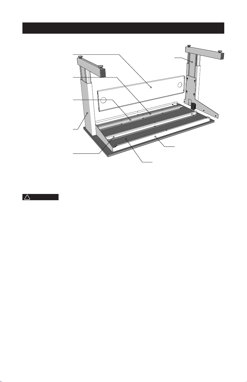
Do not attempt to assemble this product if you do not understand these instructions or you have
any doubts about the safety of the installation. Please call a qualified technician. Check carefully
for missing, damaged, or defective parts. Improper installation may cause damage or serious
injury. Do not use this product for any purpose that is not explicitly specified in this manual and do
not exceed weight capacity. The manufacturer and distributor cannot be liable for damage or injury
caused my improper mounting, incorrect assembly or inappropriate use.
WARNING
!
1200 lbs
544.3 kg
DO NOT EXCEED WEIGHT CAPACITY
Failure to do so may result in serious injury
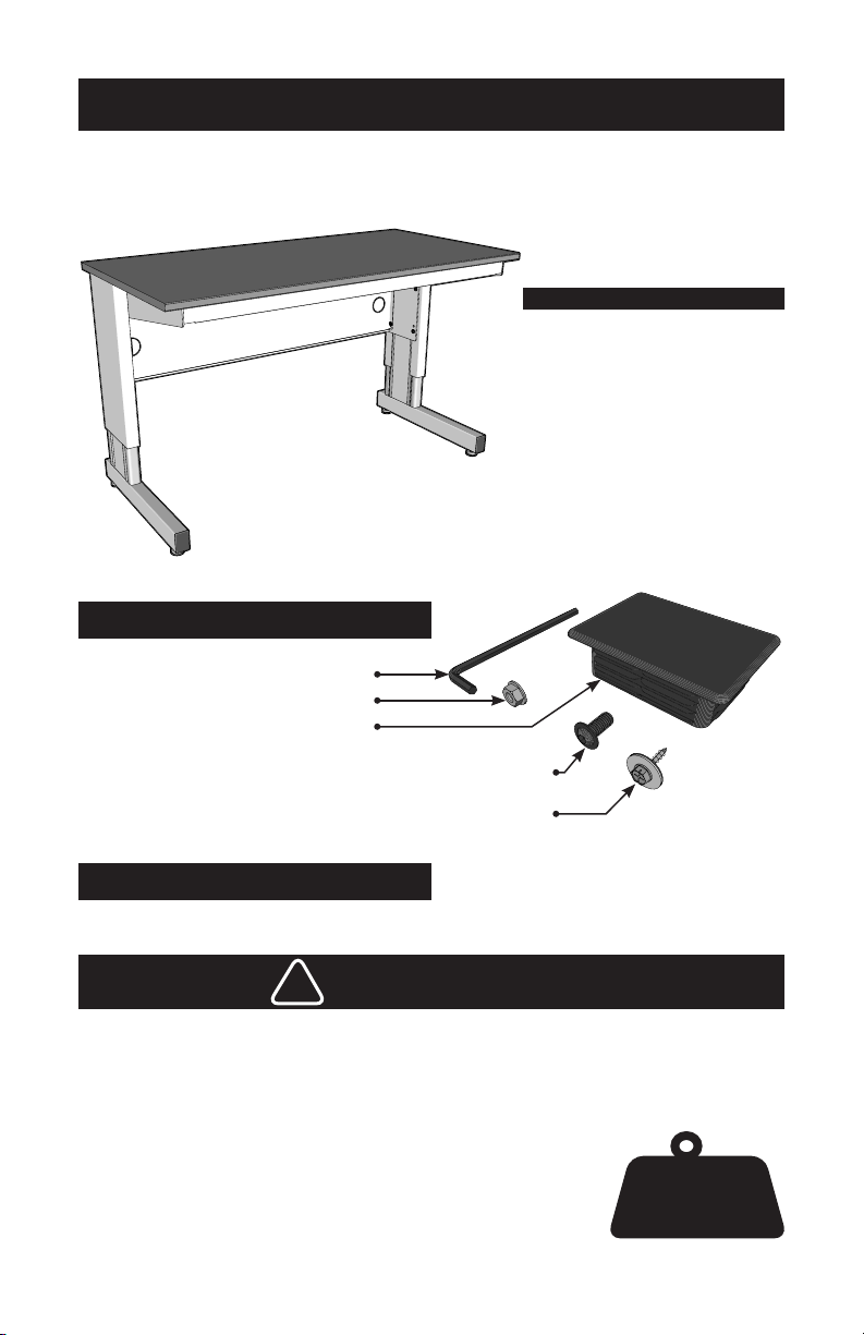
7/16" Box Wrench or Socket
Included Tools & Hardware
Tools Required (not included)
Shipped Loose
Installed on Assembly
3/16" Allen Wrench Hex Key (1)
1/4"-20 Flanged Locknut (6)
Black Plastic Access Cover (2)
5/16"-18 x 5/8" Flanged Button Head Socket Cap Screw (8)
(installed on Leg Assemblies - (4) each leg assembly)
Hex Head Screw with Neoprene Bonded Washer (11)
(fastens rails to work top)
(1/4"x 3/4" for Epoxy Top) – (1/4" x 1/2" for Phenolic Top)
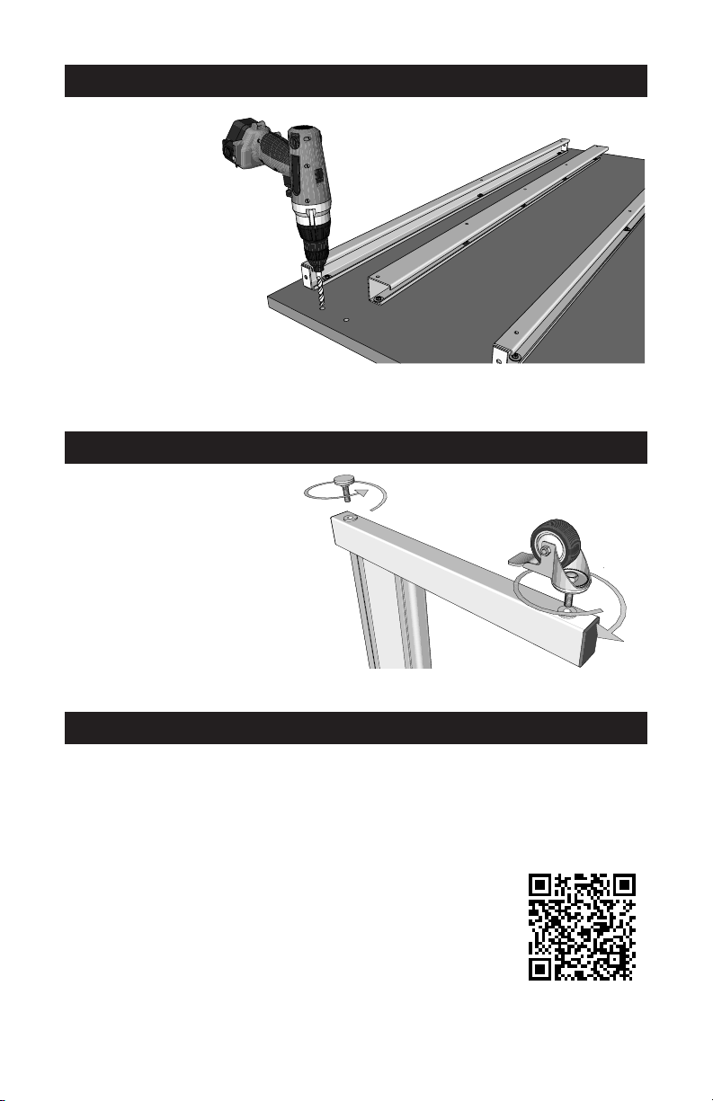
1. Before assembling
table, bore through
the 3/8" pilot holes
in the back of work
top using a 3/8"
diameter masonry bit.
(Total of 4 holes)
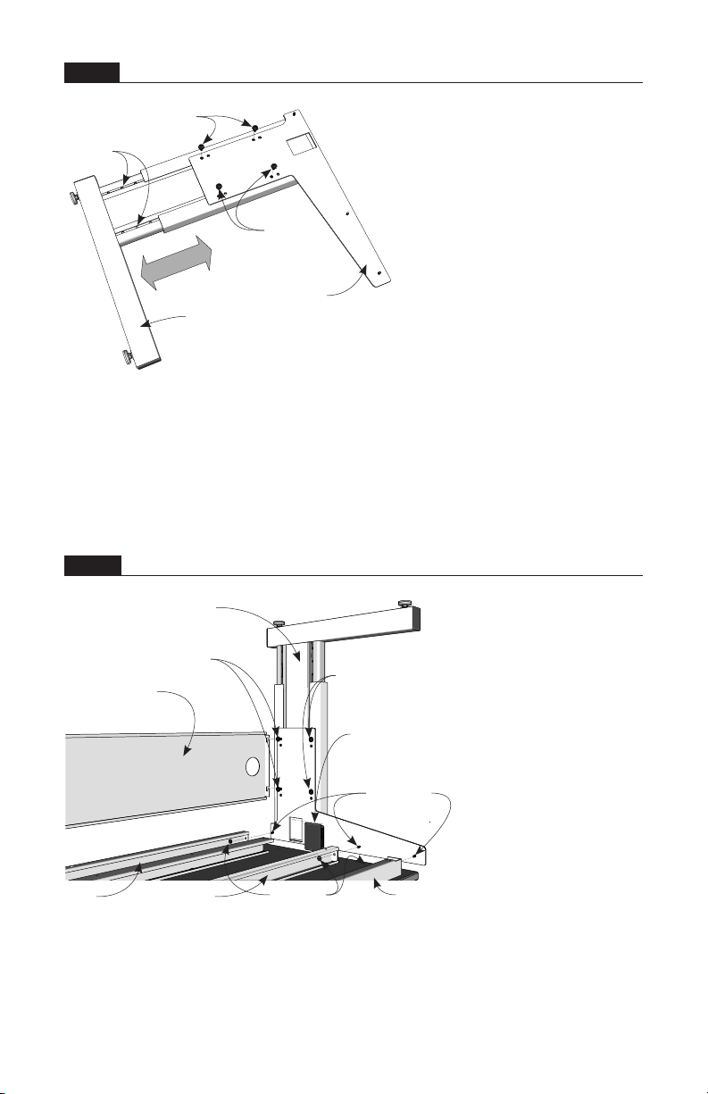
2. After table is assembled,
fasten Shelving Uprights to
top of table using (4) 1/4"-20
x 1-1/2" Hex Head Bolts
with washers as shown in
Table Shelving Assembly
Instructions.
1. Remove Glides from bottom of
Column Foot by turning counter-
clockwise. (total of 4)
2. Replace with Casters by turning the
caster stems clock-wise. Make sure
casters are fully tightened. (total of 4)
Shelving Assembly Installation
Caster Option Installation
SCAN QR CODE for
INSTRUCTION VIDEOS
Installation Manual Part No. 930090
Epoxy Top Phenolic Top
DCLT20R3036 DCLT20T3036
DCLT20R3048 DCLT20T3048
DCLT20R3060 DCLT20T3060
DCLT20R3072 DCLT20T3072
DCLT20R3636 DCLT20T3636
DCLT20R3648 DCLT20T3648
DCLT20R3660 DCLT20T3660
DCLT20R3672 DCLT20T3672