Key West Boats 230 Bay Reef User manual

Quick Guide and Schematics
230 Bay Reef

Welcome to the Key West Family!
Dear New Boat Owner,
On behalf of every employee at Key West Boats, we are pleased to welcome you to the Key West Family! For over 25
years, Key West Boats has continuously set new standards in safety, construction, and design. Our skilled team, from our laminators
and riggers to our sales and engineering department, are dedicated to every boat we build and we are constantly working to improve
our product. Our dedication to each boat and inspiration for new ideas comes from the most the important people, our customers. We
value your input and encourage you to share your thoughts with us as well as the memories you make aboard your 230BR! Owning a
boat is an amazing experience and we dedicate ourselves to making sure your 230BR will be the best experience you have on the
water…
Like all Key West Boats, the 230BR was designed and built to provide owners with unmatched safety that includes but
not limited to, its upright and level floatation that makes the 230BR both unsinkable and guaranteed to remain upright if swamped.
Although extremely safe by design, your 230BR is only as safe as the manner in which it is operated. Regardless of your experience, we
encourage you to read the generic manual we have provided with your boat and other resources for information on rules of the road
and safe boating practices to ensure you are operating your boat safely and within the rules at all times.
Like all Key West Boats, the 230BR was designed to be low maintenance, ergonomic and an efficient boat to maintain
and operate. Familiarizing yourself with the boats systems and working closely with your dealer will go a long way in providing that.
We are pleased to provide you with this guide and schematics of the systems in the 230BR to ensure you are confident before you step
aboard for your first memorable trip! Following the information in this guide and your dealer’s service plan will help to provide you
with many years of reliable service so that you can consistently enjoy your time on the water, experience things only possible with and
discover the joy that owning a 230BR brings!
Finally and most importantly, like all Key West Boats, your 230BR was built by a dedicated and experienced team who
gave it a unique and personalized story that started when you and your dealer gave it a unique and one of a kind character. 25+ years
and over 20,000 boats later, we still look at each boat we build as having its own unique character, story and as an important part of
our family. Your 230BR is not just another “Unit” and becoming the owner of this 230BR does not make you just another “customer”.
It makes you a part of our family, a family we have been dedicated to for over 25 years and is over 20,000 unique and personalized
stories strong. We are honored to have you part of our family and write another unique and personalized story…Safe passages and
Tight Lines!
Sincerely,
The Key West Team

Fuel System
The 230BR is equipped with a single, 80 Gallon, pressurized fuel tank. The tank is of Polyethylene construction and is insulated with foam during
the construction of the boat. The tank is located on centerline between the aft livewell and aft end of the console. There is a sending unit installed
in the tank. Inspection ports in the deck and head compartment provide access to tank fittings.
There is a fuel pickups installed in the tank. The pickup incorporates a shut off valve along with an anti-siphon valve than can be accessed through
the in deck inspection plate under the leaning post.
There is an on deck fuel fill located on the port side of the boat, just forward of the console. Access to the fill is provided through an inspection
port. The tank vents through an EPA Carbon Canister, located in the anchor locker, which than vents overboard through a vent fitting on the
starboard side of the hull. Access to the vent is provided through an inspection port. It is recommended that these connections be inspected
annually.
The 230BR will come pre-rigged from the factory with an engine matched fuel water separator. The fuel water separator is installed in the bilge
and accessed through the bilge access hatch located in the engine pod. The fuel water separator should be checked periodically to ensure the fuel
is free of water. Fuel should be disposed of in an approved waste collection device when servicing/replacing. The filter must be filled with fuel
after servicing/replacing them in order to prime the engine.
A primer bulb for the engine is located in the engine pod. It is used to prime the system before starting the engine. This should be done after
service or after long periods of downtime for the boat.
All components of the 230BR Fuel System are approved for use with ethanol blended fuels up to 10%. E85 fuel should never be used. Key West
recommends using non ethanol fuels whenever possible to reduce the risk of moisture retention in the fuel system, especially in areas of high
heat/humidity.
When refueling the 230BR, whether on trailer or at a marina, the pressurized system will prevent overfilling. During fueling, check to ensure air is
escaping from the tank vent on the starboard side. Any blockage of the vent, vent line and/or orifice line will prematurely trigger the shut off on
the fuel nozzle and will prevent you from filling the tank completely.
Due to the emission requirements of the EPA, certified fuel tanks and systems will not fill to the top of the tank. Instead, there will be a ullage in
the top 10% of the tank. The specified capacity of the tank (100 Gallons) accounts for this ullage, however it is important to note that fuel senders
do not account for this. Therefore, filling the tank to 100 Gallons will not indicate “Full” on the gauge. When using your boat, it is a good practice
to keep a log and a running count of how much fuel you’ve used. Do not rely on the fuel gauge exclusively as variations will occur.


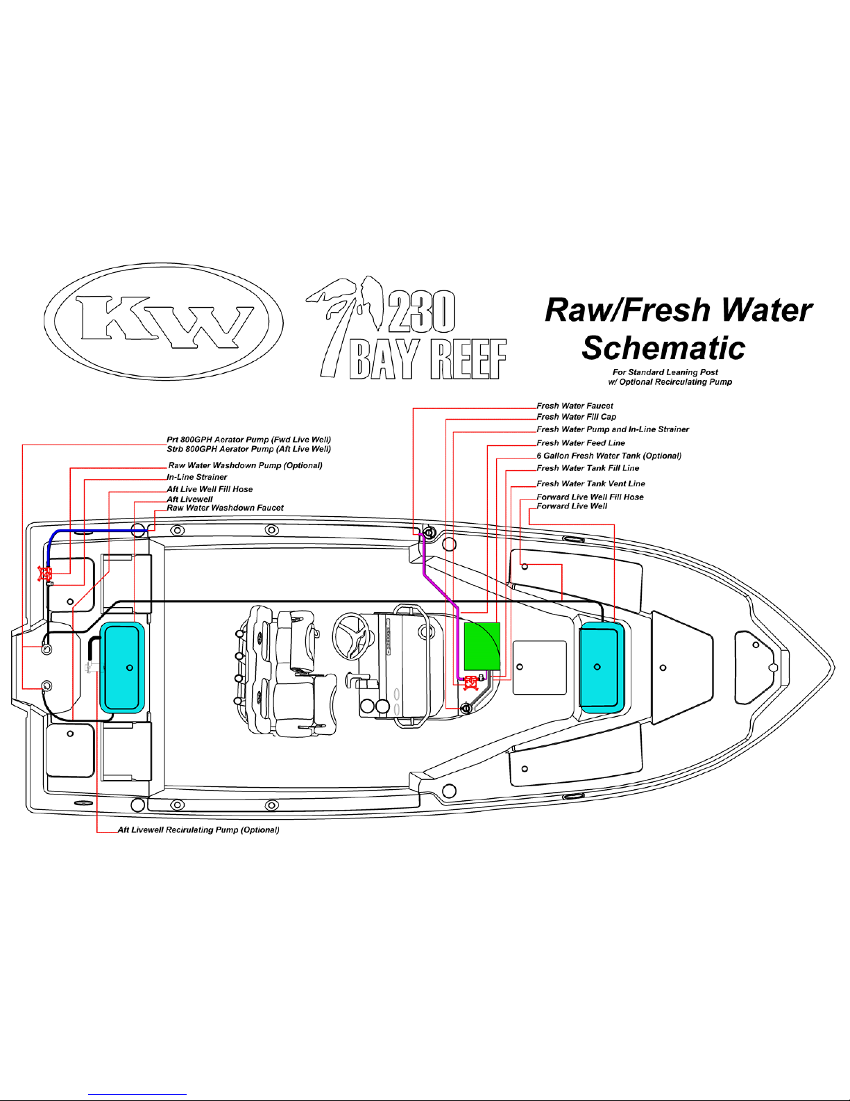
Raw Water System (Livewells)
The 230BR features a raw water system for the aft and forward livewells, optional leaning post livewell, optional raw water washdown system and
optional aft livewell recirculating system.
Raw Water Supply
The 230BR features two high speed venturi pickups for raw water intake. The pickups incorporate a seacock. Before using the boat, it is important to
note the location of the seacocks and the means to achieve access to them. In the event of a rupture in a raw water line or pump that allows unrestricted
flow of water into the bilge, shutting the seacock will be critical. Seacocks should be checked periodically and the valves moved to verify operation and
unrestricted movement. If problems are found, they should be addressed immediately by your dealer.
Forward and Aft Livewell Fill System
There are two 800GPH livewell pump. They are directly mounted to the seacocks. The port pump provides raw water to the forward livewell. The
starboard pump provides raw water the aft livewell and the optional leaning post livewell. The pumps have a independent switches and circuit breakers
(See Electrical Schematics). To use the livewells, it is important to check and verify the seacocks are open. Failure to open the seacocks may result in
pump failure if the pump is run dry for an extended period of time. The livewell pumps have a pressure regulator that will shut the pump off if the
livewell fill valves are not open. If trailering the boat or using the boat after an extended period of downtime, it will be necessary to prime the pumps.
Before activating the pumps, make sure the livewell fill valves are open and than switch on the pumps. When the system is free of air, you can either
shut the fill valve in the livewells or shut off the pumps. It is important to check the livewell pumps annually and periodically spray it/them with a
corrosion inhibitor.
Aft Livewell Recirculating Pump (Optional)
The 230BR can be equipped with a recirculating pump for the aft livewell. A recirculating pump is a pump that pulls water from the bottom of the
livewell, aerates it and than returns it to the top of the livewell. The normal livewell system does this, however it is continuously replacing water by
drawing it from the raw water intake. In deeper water, this is the best way to keep water fresh and cool. However, when operating in shallow water
where the water is muddy or sandy, the recirculating pump allows you to recirculate and aerate clean water so that you are not drawing in dirty water
that could harm your bait. In the 230BR, the recirculating pump is mounted directly to the aft end of the livewell. The return from the pump is in the
top aft corner of the livewell. The pump is an 800GPH pump and has an independent switch and circuit breaker (See Electrical Schematic). The pump
will prime itself whenever water is above the intake screen of the pump. To use the pump, activate the switch. There are no valves to open. Water will
begin circulating immediately provided there is enough water in the livewell. Never run the pump without a sufficient amount of water in the livewell.
Running the pump dry for extended periods of time may damage the pump resulting in failure. The recirculating pump can be run in conjunction with
the aft livewell pump to provide increased circulation and aeration, however it is not necessary.
Leaning Post Livewell (Optional)
For anglers who want an additional and larger livewell, the 230BR can be equipped with a Livewell Leaning Post. The Livewell Leaning Post provides
great flexibility to anglers, especially tournament anglers because it allows the aft livewell to be used as release well if they wish, capable of circulating
water either via the livewell fill system and/or the optional recirculating pump. Raw water to the livewell leaning post is supplied via the starboard
livewell pump. A T-Connector is installed so that raw water can be used by both the aft and leaning post livewell. The livewell features a fill valve,
identical to the forward and aft livewell. This allows you to fill and use the aft livewell, the leaning post livewell, or both depending on your fishing
needs. To use the Livewell Leaning Post, engage the aft livewell pump and open the fill valve in the livewell.

Raw Water System
Standard Raw Water Wash System
The 230BR is equipped with a raw water wash system. The system uses the starboard livewell pump to provide raw water to the provided washdown
hose. Please note though that using the system does not allow use of the aft livewell. To use the system, unscrew the livewell fill valve in the aft livewell
and thread the hose onto the inlet. The livewell pump is pressure regulated so that the pump can be left on, even when not using the wash down. If
trailering the boat or using the boat after an extended period of downtime, it will be necessary to prime the system. Before activating the aft livewell
pump, depress the nozzle on the washdown hose and than switch on the pump. When the system is free of air and a steady stream of water is coming
from the hose, the system is bled.
Optional High Pressure Washdown system
The 230BR can be equipped with an optional high pressure, raw water washdown system. The system is fed by a pump that is located in the aft end of
the port transom dry storage compartment. The pump is controlled by a switch and circuit breaker (See Electrical Schematics). Water is supplied to the
pump off of the accessory port on the port livewell pump(lower hose connection on the livewell pump). Using the raw water washdown does not
require the livewell pump to be on however the port seacock must be open. Failure to open the port seacock may result in pump failure/damage if the
pump is run dry for an extended period of time. The raw water pump features an in-line strainer for collecting any debris that could damage the pump.
The strainer should be checked before using the pump. The strainer features a clear cap for easy inspection. If any debris is found, remove the strainer
screen by untwisting the clear cap and clean the screen. The pump features a built in pressure regulator that will shut the pump off when pressure is
achieved in the system. The raw water washdown faucet is located on the port side side under the gunwale cap, adjacent to the port jump seat. If
trailering the boat or using the boat after an extended period of downtime, it will be necessary to prime the washdown pump. Before activating the
pump, open the washdown faucet and than switch on the pump. When the system is free of air, you can either close the faucet or shut off the pump. It is
important to check the washdown pump annually and periodically spray it with a corrosion inhibitor.
System Operation and Maintenance
When using any of the two/three raw water pumps, it is important to pay attention to the water you are operating the boat in. Operating the pumps in
shallow/muddy water or water with high amounts of floating debris such as grass or trash may result in ingestion and damage the pumps. Loss of
pressure in pumps may be the result of containments blocking the thru hulls, binding of the pumps impellor, clogged strainer basket and/or blockage in
lines. When operating in the contaminated water, check the supply of and quality of water to the livewells or washdown frequently. Any loss of
pressure or flow should be addressed immediately to prevent damage. If fishing and installed, use the aft livewell recirculating pump to circulate and
aerate the water so that you can continue to fish with fresh bait without worry of damaging the raw water pumps.

Raw Water System Troubleshooting
Baitwell and/or Raw Water Pumps Run, but do not pump water
•Pickup(s) is blocked and is preventing water from reaching the pumps. Put boat in reverse to clear the intake. If
problem persists, do not continue to operate pumps. Clean intake when boat is out of water to remove debris
•There is air in the raw water washdown system. Prime the system as described on previous page
•Seacock is not open. Open Valve
•Raw Water Pump Strainer is clogged. Clean Strainer
Baitwell and/or Raw Water pumps run but water flow is reduced
•Seacock is not fully open. Open seacock valve fully
•Debris is partially blocking raw water intake. Clear debris
•Raw Water Pump Strainer is partially clogged. Clean Strainer
•Baitwell sprayer head Valve is not fully open. Open Valve fully
•Raw Water Faucet is not fully open. Open Valve Fully
•Hose(s) are damaged and are either leaking and or sucking air. Check hoses
•Low Voltage to Pump(s). Check connections for loose or corroded wiring. Check battery voltage
•Pump(s) are damaged or defective. Replace Pump(s)
The Raw Water washdown pump continues to run, even after faucet is closed
•The intake hose going to the pump is damaged and is sucking air. Replace hose
•Intake hose is loose causing a leak and loss of pressure to the pump. Inspect connections at both the livewell pump
and washdown pump to ensure they are tight.
•Discharge hose from pump to faucet is loose causing a leak and drop of pressure. Inspect connections and fittings
at both the pump and faucet to ensure they are tight and not damaged. Replace if damaged
•Strainer is clogged. Clean Strainer
•Pressure switch on pump is defective. Replace pump or pressure switch
•Voltage to the pump is low. Check connections for loose or corroded wiring. Check battery voltage
•Pump is damaged or defective. Replace Pump

Fresh Water System (Option)
Fresh Water Supply
Fresh water is stored in a 6 gallon tank located under the console floor, directly below the console cooler box. Access to the tank is achieved through a
hatch inside the console. The tank features a fill line, vent line and supply line. These fittings should be checked annually. It is critical that only potable
water be used in the tank. Failure to do so will require overhaul of the entire freshwater system.
Fresh Water Fill and Vent
The fresh water tank is filled from a fill deck plate marked “WATER”. It is located on the starboard side of the console cooler seat. Before filling the tank,
verify the quality of the water and make sure area around the fill is free of containments that could enter the tank. While filling, verify the tank is venting
through the tank vent which is located on the front side of console seat. An absence of air escaping from the vent may indicate a blockage or kink in the
vent line. This will result in the tank failing to fill all the way which will show in water flowing out of the fill well before coming out of the vent. It will
also diminish the performance of the fresh water system as a blocked vent will create a vacuum in the tank as water is used, thereby resulting in less
water to the pump, continuous cycling of the pump and loss of water pressure. This could ultimately result in damage to the pump. Check the vent line
periodically to ensure there are no kinks or blocks.
Washdown Pump
The fresh water washdown system is fed by a pump that is located adjacent to the water tank. The pump is controlled by a switch and circuit breaker
(See Electrical Schematics). Water is supplied to the pump from the tank outlet located on the bottom of the tank and is gravity fed from the weight of
the water in the tank. This allows all 6 gallons to be used. The fresh water pump features an in-line strainer for collecting any debris that could damage
the pump. The strainer should be checked periodically and features a clear cap for easy inspection. If any debris is found, remove the strainer screen by
untwisting the clear cap and clean the screen. The pump features a built in pressure regulator that will shut the pump off when pressure is achieved in
the system. The fresh water washdown faucet is located on the port side under the gunwale cap, just forward of the console. If the system has not been
used for a period of time, it may be necessary to prime/bleed the system of any air. Before activating the pump, open the fresh water washdown faucet
and than switch on the pump. When the system is free of air, you can either close the faucet or shut off the pump. It is important to check the
washdown pump annually and periodically spray it with a corrosion inhibitor.
Hardtop Mister Pump (Optional)
As an optional upgrade for boats with hardtops, the 230BR can be equipped with a mister system. The Mister system uses its own pump, separate from
the freshwater washdown pump. The freshwater pump does not need to be on to use the mister system. The pump is located adjacent to the fresh
water pump in the console. The pump is controlled by a switch and circuit breaker (See Electrical Schematic). Fresh water is supplied to the mister
pump from a T-Connector in the main supply line from the tank. The mister pump features an in-line strainer for collecting any debris that could
damage the pump. The strainer should be checked periodically and features a clear cap for easy inspection. If any debris is found, remove the strainer
screen by untwisting the clear cap and clean the screen. The pump does not feature a pressure regulator and will run continuously when switched on.
System Operation and Maintenance
Only use potable fresh water in the system. Always verify there is sufficient quantity of water in the tank before activating either the washdown or
mister system. Insufficient water quantity will cause the pumps to run dry and may lead to failure/damage. Before using the freshwater system for the
first time on the water, fill the tank and cycle all the water out to ensure the tank is clean and free of contaminants. Afterwards check strainer(s) for
debris and clean if necessary.

Fresh Water System Troubleshooting
Fresh Water Pump Runs, but does not pump water
•Water Tank is empty. Fill the Tank
•Intake hose from the tank to the pump is damaged causing the pump to suck air. Check Hose
•Strainer is clogged. Clean Strainer
Fresh Water Pump Run, but flow is reduced
•Intake hose from the tank to the pump is damaged causing the pump to suck air. Check Hose
•Water Tank vent line is kinked or blocked creating a vacuum in the tank. Check Vent Line
•Strainer is partially clogged. Clean Strainer
•Fresh Water Faucet is not fully open. Open Valve fully
•Partial block or kink in hoses between pump and faucet. Check hoses
•Low Voltage to Pump. Check connections for loose or corroded wiring. Check battery voltage
•Damaged or defective pump. Replace pump
The Fresh Water washdown pump continues to run, even after faucet is closed
•Intake hose from the tank to the pump is damaged causing the pump to suck air. Check Hose
•Water Tank vent line is kinked creating a vacuum in the tank. Check Vent Line
•Strainer is clogged. Clean Strainer
•Pressure Regulator in pump is defective. Replace pump or pump regulator
Fresh Water Tank runs out of water excessively fast
•Leak in the tank or leak in intake hose going to the pump. Check tank integrity by filling all the way and inspect for
leaks. If Leak is found, consult dealer regarding repair/replacement. Check connections on intake hose to the
pump for leaks.
•A kink/block in the Water tank vent line can cause the tank to fill up prematurely, even though it isn’t full due to
lack of air escaping. Check tank vent line and ensure it is not blocked or kinked.


Drainage System
General Overview
All water in the 230BR is drained either via gravity or pump. It is either drained directly overboard or to the aft bilge where it can be drained out either
via the garboard drain plug or the bilge pump. It is important to check the drainage system frequently to verify water flows freely, hoses are secure and
there are no leaks. The drains and discharge pumps are as follows starting at the bow:
Anchor Locker –Gravity drain along centerline of hull to aft bilge
Port Bow Locker –Gravity drain to bilge
Starboard Bow Locker –Gravity drain to bilge
Center Bow Box Drain –Gravity drain to bilge
FWD Livewell Overflow Drain –Gravity drain connects via T-Connector to FWD Livewell Drain
FWD Livewell Drain –Gravity drain to starboard transom 1-1/8” Thru Hull
Bucket Box Lip Drain –Gravity drain runs to 1-1/8” Transom Drain
Bucket Box Drain –Gravity Drain to Bilge
Console Recess Drain –Gravity drain, drains directly to the bilge
Livewell Leaning Post Overflow Drain (Optional) –Gravity drain connects via T-Connector to Livewell Leaning Post Drain
Livewell Leaning Post Drain (Optional) –Gravity drain to Centerline 1-1/8 Thru Hull on transom.
Port Cockpit Drain –Gravity drain to port transom 1-1/2” Thru Hull
Starboard Cockpit Drain –Gravity drain to starboard inboard 1-1/2” Thru Hull
Port/Starboard Transom Storage lockers–Gravity drain directly to aft bilge
Aft Livewell Overflow Drain –Gravity drain connects via T-Connector to aft Livewell Drain
Aft Livewell Drain –Gravity drain to port transom 1-1/8” Thru Hull
Bilge Pump –Located in aft bilge, discharges to aft port thru hull near transom


Floor Drain Overview
Two of the most important pieces of equipment on your 230BR are the cockpit floor drains as their operation is integral to
your safety on the water. At 1-1/2” in diameter, they are designed to allow massive quantities of water to leave the cockpit of your boat in a
very short period of time in the event of a swamping or extreme down flooding event. All the drains in your 230BR operate this way,
however, the floor drains are designed so that water can only flow in one direction; out of your boat. The drain features a unique design
that acts like a check valve thereby preventing backflow of water into the cockpit of your boat.
The design of the drain and its operation is solely dependent on the foam ball and seal ring. Any degradation in the foam will
compromise the balls ability to seal against the seal ring. Therefore, do not apply power washers or any cleaning chemicals directly to the
drain area as this will compromise the foam in the ball. When using chemical cleaners in your boats interior, use a sufficient quantity of
water to dilute the chemical(s) when spraying off so that they do not affect the foam ball when draining out.
The seal ring needs to be kept free of debris so that foam ball will seal flush. The drain features a grate so that debris cannot
flow into the drain. In the event that a sufficient amount of debris collects around the seal, the grate and top of the drain assembly can be
removed. Use a spanner wrench to unscrew the top of the drain and clean the drain assembly. This will also provide access to the foam
ball which can than be removed and replaced if necessary. Only do this if it becomes evident that ball is not sealing properly. This will be
manifested by small amounts of water coming through the drain when the boat is sitting at rest in the water. DO NOT remove the drain
while the boat is in the water.
Whenever the thru hulls are
submerged below water, back
pressure seals ball against seal ring,
creating a watertight seal and
prevents backflow of water from the
thru hulls.
Under normal conditions when
the thru hulls are above water,
the ball is below the seal ring
thereby allowing water to flow
out of the cockpit and
overboard

Drainage System Troubleshooting
Reduction in water flow from bilge pump
•Blue Intake screen on bottom of pump is clogged with debris. Clean Intake Screen
•Voltage to the pump is low. Check for corrosion and loose connections. Check battery Voltage
•Discharge hose is blocked or kink. Check discharge hose and clean/repair
•Pump is defective. Replace Pump
Bilge Pump continues to run even though bilge is dry
•Float switch on pump is stuck due to debris or build up on switch. Ensure float switch is clean and free of debris
Bilge is full of water and pump is not running
•The Inline Fuse for the automatic bilge pump is blown. Replace the Fuse
•The battery is dead. Check voltage and charge if necessary
•The pumps impeller is clogged by debris. Clean pump impeller
•The connections/wires to the pump are corroded. Check and replace connections/wires
•The Built-In float switch is defective. Replace Pump
•The Pump is defective. Replace Pump
Bilge pump will not run when the manual switch on the helm is engaged
•Circuit breaker below the pump’s switch is tripped. Reset circuit breaker.
•The battery switch is off or the battery is disconnected. Turn on battery switch/reconnect battery
•The pumps impeller is clogged by debris. Clean pump impeller
•Switch is defective. Replace the switch
•The connections/wires to the pump are corroded. Check and replace connections/wires
•Pump is defective. Replace Pump

Electrical System
General Overview
The 230BR is equipped with a 12V DC Electrical system that can be equipped with an optional AC battery charger. The 230BR can only be
rigged for a single motor. If the boat is rigged without an optional battery selector switch, the boat will be rigged for x1 Group 27 battery. If
the battery selector switch is installed, the boat will be rigged for x2 Group 27 batteries. The battery(s) will provide power to the engine,
house and optional windlass system.
12V power is distributed to the 12V factory installed systems through individual circuit breakers located beneath their respective switches
on the main switch panel. All 12V systems are grounded individually to a grounding block located inside the console. The grounding block
is than grounded directly to a battery. A 50amp main circuit breaker is installed in the console to protect the house systems from overload
and is connected either directly to the batteries or the optional battery selector switch. Additional circuit breakers for the auto bilge pumps
and stereo memory are wired directly to either the battery or battery selector switch.
The system is designed so that turning the battery switch off will still allow the bilge pump to function in an automatic mode. Key West
recommends that boats that are going to be left in the water or in a boat lift, where access to the drain plug is not feasible, be installed with a
battery charger to prevent discharge by the bilge pump. Trim Tabs are connected directly to the battery and feature overcurrent protection.
They do not energize until the engine ignition switch is turned to the “On” position.
Battery Selector Switch (Optional)
As an option, a battery selector switch can be installed. The battery selector switch is installed on the starboard side of the console. The
battery switch provides power to the engine and 12V accessories. The switch is a dual circuit switch and has 4 positions (OFF, 1, 2, Both).
This allows power to be supplied by either battery 1, battery 2, or both simultaneously. The switch also directs the charging current from
the engines alternator.
If position “1”, is selected on the switch, the engine and 12V accessories will receive power from Battery 1 and the engine’s alternator will
charge Battery 1. Battery 2 will be isolated and in reserve. If position “2”, is selected on the switch, the engine and 12V accessories will
receive power from Battery 2 and the engine’s alternator will charge Battery 2. Battery 1 will be isolated and in reserve. If position “Both”
is selected, the switch connects the batteries in parallel and the engine and 12V accessories will receive power from both batteries. The
engine’s alternator will charge both batteries simultaneously as well. When the boat is underway, placing the switch in the “Both” position
is recommended so that both batteries charge. When the boat is moored (Engine Off) and 12V accessories are being used, it is
recommended to select position “1” or “2” so that one battery is isolated and can be used to crank the engine. When using the windlass, it is
recommended to place the battery switch in the “Both” position due to the high power demand.

Electrical System
Optional T-Top/Hardtop
If your 230BR is installed with an optional canvas T-Top or Fiberglass Hardtop, it will be rigged with spreader lights and additional courtesy lights.
These lights are controlled by switches located on the port side of the electronics box. A Fuse block with ATC fuses is installed inside the
electronics box to provide overcurrent protection. Power is supplied to T-Top/Hardtop accessories via a single red wire that is connected to the
50amp house breaker inside the console. It connects to the fuse block where power is than distributed to the T-Top/Hardtop accessories through
their respective fuses. All T-Top/Hardtop accessories are grounded to a grounding post on the fuse block that is connected directly to a ground on
one of the two batteries via a single black wire.
Battery Charger
As an option, a battery charger can be installed that will charge one or both batteries, depending on the battery installation. The battery charger
converts AC power into DC power that is used to charge the batteries. The charger is powered by a plug on the console that receives a standard
110V plug from the female end of a 110V extension chord. It allows you to plug the boat into a regular 110V outlet. Please consult the battery
charger’s manual before using your charger for the first time. If the optional Battery selector switch is installed, it does not need to be on to direct
the charge from the battery charger.
Trolling Motor Packages
The 230BR comes from the factory pre-rigged with a trolling motor harness so you can add a trolling motor at any time. If you choose to, a 24V or
36V trolling motor can be installed at the factory. Both packages come with a battery charger that will charge the trolling motor batteries. 24V
trolling motors will be rigged with two batteries in series that are located inside the console. 36V trolling motors will be rigged with three
batteries in series. Two will be located in the console and the third located in the port transom storage box. A circuit breaker is installed in the
console that allows you to disconnect the batteries from the trolling motor harness whenever the boat is stored or the trolling motor is not being
used. The trolling motor harness features a plug and receptacle located in the bow. To use your trolling motor, insert the plug into the receptacle
and make sure the trolling motor circuit breaker is closed. The trolling motor’s electrical system is completely isolated from the 12V House and
engine systems. The charging system on the engine is not designed to charge the trolling motor batteries. The trolling motor batteries can only be
charged via the battery charger that comes with the trolling motor package. If you anticipate using your trolling motor, fully charge the batteries
before each use. Low voltage in any of the two or three batteries will cause the motor to not function properly. Please see “Dealer Installed
Equipment” section on next page for further information regarding battery installation.

Electrical System
Electrical System Maintenance
All connections in the electrical harness feature deutsche connectors and heat shrink butt connectors to minimize corrosion. Key West
recommends that all connections and terminals be checked at least twice a year and sprayed with a corrosion inhibiting spray at least once a year
to protect and maintain the integrity of electrical connections.
Dealer Installed Equipment
When your 230BR arrives at your dealer, the dealer will install batteries and may install additional equipment. It is important to check with your
dealer regarding the batteries installed in your boat. The three common types of batteries are Wet Cell, Gel Cell and AGM Batteries. Gel Cell and
AGM batteries are sealed and maintenance free. If your boat is equipped with Wet Cell batteries, they will require the following inspections and
service. Regularly check the electrolyte levels in the batteries and add DISTILLED WATER if needed. If a battery charger is used regularly, the
electrolyte levels will need to be replenished more often. Fluid level should be just above the plates in the battery. Do not overfill. Only use
distilled water. If your boat is installed with a battery charger, before using the charger, make sure the charge mode is set to the battery type (Wet,
Gel, or AGM) installed on your boat. If a battery needs to be replaced, make sure it is the same type as the other battery. It is ok to install a larger
or smaller battery provided it is the same type (Wet, Gel, or AGM) as the other battery in the boat.
Consult with your dealer regarding wiring and installation of electronics installed at the factory. If equipment is connected to available accessory
switches on the dash panel, your dealer’s service department should verify the capacity of the circuit breaker and current demands of the
equipment being installed so that proper overcurrent protection is provided. Verify that installed equipment does not overload the capacity of the
50amp main breaker installed inside the console when all 12V accessories are running.

This manual suits for next models
1
Table of contents
Other Key West Boats Boat manuals

Key West Boats
Key West Boats 189/203 family sportsman User manual

Key West Boats
Key West Boats 2014 KW 211 DC User manual

Key West Boats
Key West Boats 239DFS User manual

Key West Boats
Key West Boats 244 CC BLUEWATER User manual

Key West Boats
Key West Boats 1720CC User manual

Key West Boats
Key West Boats 239FS User manual

Key West Boats
Key West Boats 239DFS User manual

Key West Boats
Key West Boats 2015 176BR User manual

Key West Boats
Key West Boats boats Manual

Key West Boats
Key West Boats Family Sportsman Series User manual