KEYA DC12/48RT100BL-XW User manual

DC12/48RT100BL-XW
Driver Operation Manual
Jinan Keya Electronic Technology Co., Ltd.

Please read this operation manual thoroughly before using this device.
Any failures and damages caused by non-compliance of precautions stipulated in this operation and
installation manual are beyond the scope of warranty and the manufacturer disclaims any
responsibility for them. This manual must be carefully kept. In case of any question, please contact
us!
Safety precautions
·Installation, connection and commissioning of this device shall be carried out by professionals.
·Do not install, remove or replace device circuit under charged circumstances.
·Please make sure that necessary protectors are mounted between power input end of this device
and power supply (storage battery) to avoid accidents or fatal damages; Devices need to be
mounted: over-current protector, fuse, emergency switch.
·Isolation and insulation protection between device and ground as well as devices shall be well
equipped.
·In case that charged commissioning of this device is really needed, well-insulated nonmetal
special screwdriver or special commissioning tools shall be used.
·This device shall be installed in well-ventilated environment.
·This device shall not be directly exposed to abnormal environments with high humidity, dust,
corrosive gas and intense vibration.
This picture identify an important notice or warning.

Overview:
Keya - DC12/48RT100BL-XW is a kind of intelligent high-power DC motor driver. This driver
uses high-performance MCU, adopts advanced motion control algorithm and is applicable to
situations having special functional requirements and has external analog quantity, pulse-width
control and potentiometer speed governing functions. It can sets soft start and stop as well as
maximum current and motor torque, separately selects forward and backward rotations of motor and
separately controls forward limit and backward limit. This driver is also equipped with fault alarm
output end to effectively protect the reliability and safety of device package and can be widely used
in automation control industry.
II. Specifications and Model:
Max. Max. DC voltage
Output current Output voltage Input range
Model AC: (A) DC: (V) DC: (V)
DC12/48RT100BL-XW 100 50 10- 50
III. Characteristics:
◆Small size.
◆Wide voltage input.
◆Multiple control modes: Potentiometer, analog control, pulse-width control
◆Independent forward & backward control.
◆Independent forward &backward limit
◆Brake control.
◆Maximum current limit.
◆Protections started under abnormal conditions: Over-current, over-heat, over-voltage,
under-voltage, short circuit, etc.
◆LED fault alarm status indicator, fault alarm output.
IV. Performance index:
1. Supply voltage: 10—50VDC.
2. Standby current: 6mA.
3. Continue working current: 50A High instant current: 100A-60S.
4. Working frequency: 2KHZ.
5. Out+5VDC Power supply (can be supplied to potentiometer): 5V DC 20mA
6. Input range of analog quantity: 0-- 5VDC or 0-10VDC

7. Soft starting time: 0-5S
8. Soft stopping time: 0-5S
9. Pulse input frequency: 250Hz
10. Input range of duty ratio: 0-- 100%
11. Digital quantity output interface: Maximum load capacity is 50v 1A.
12. Temperature protection status: stops output at 80℃
13. Operating temperature:-30℃-- +60℃
14. Environment humidity: relative humidity≤80RH.
15. Boundary dimension: L * W * H = 210mm * 115mm * 63mm
16. Weight: 975g
V. Boundary dimension:
Boundary Dimensional Drawing

Note: 4*Φ5mm mounting hole is equipped on the bottom of driver housing to facilitate horizontal
installation.
This driver shall be kept away from dust, high-humidity environment and accidental contact shall
also be avoided. Enough space shall be reserved around the driver for ventilation and regulation.
When fixed, this driver shall be kept away from other heat source. Guarantee that this drive works
within the range of specified environment temperature. Installed on equipments with intense
vibration is not recommended; if not, please take precautions against vibration.
I. Wiring requirements:
1. Do not connect wire under charged circumstances.
2. Insulated wire and shielded wire matching well with driver’s voltage and current shall be selected
for the device; Specifications of power input line and motor connecting line selected for the driver
are shown in following table:
Table 1 Specification and length of wires
Current (A) Wire specification (
2
mm
) Max. length (m)
Power input line: 100 10 15
Motor output line: 100 10 15
WARNING
In any cases, signal line and logic control wire is not allowed to be bound, mixed or wired with
power input wire, output wire (motor wire) and other power lines, induced voltage generated
may cause interface, malfunction or direct damages upon the driver.
3. As driver does not have internal protection of opposite connection, please be sure to guarantee
that positive and negative poles of power input are consistent with that of external power supply,
otherwise, damages may be caused.
4. Please use proper tools for wiring and guarantee its correctness.
VII. Terminal connection diagram:

WARNING
All output connecting lines which control the terminal shall be kept away from wires
at power supply end and output end.
As output voltage supplied by the driver is 5V and current is 20 mA (small), other
external loads (such as data display instrument, indicator light) shall not be
connected, otherwise, damages may be caused.
n order to reduce unnecessary electronic signal interference, length of connecting
lines which control the terminal shall be shortened as much as possible, in case that
length of connecting line exceeds 0.5m, shielded wire shall be adopted.
VIII. Potentiometer control:
Potentiometer control: a 2W/10K potentiometer shall be used to control speed governing of the
driver; wiring diagram is shown below.
Installation method:

WARNING
Be sure to use shielded wire for signal input and shielding net shall be single-ended grounded.
Be sure to use shielded wire for all control signal connecting lines and shielding net shall be
single-ended grounded.
IX. Analog quantity control: External 0-5V control
WARNING
Be sure to use shielded wire for standard signal input and shielding net shall be single-ended
grounded.
Be sure to use shielded wire for all control signal connecting lines and shielding net shall be
single-ended grounded.
X.Pulse control: duty ratio regulation, frequency is 250 HZ, amplitude is 5V

WARNING
Be sure to use shielded wire for signal input and shielding net shall be single-ended grounded.
Be sure to use shielded wire for all control signal connecting lines and shielding net shall be
single-ended grounded.
XI. Motor forward and backward control:
Forward start Backward start
Forward start: FW and COM shall be shorted connected, i.e. forward run.
Backward start: BW and COM shall be shorted connected, i.e. backward run.
Note:
In case that COM terminal is not shorted connected with FW or BW terminal, driver is inoperative.
In case that COM terminal is shorted connected with FW and BW terminal at the same time, driver
is inoperative.
XII. Brake control:
Brake control
Brake control: STOP and COM terminal shall be shorted connected, i.e. motor will be immediately
stopped.
Note: In case of forward brake, if link between STOP and COM is not disconnected, backward start

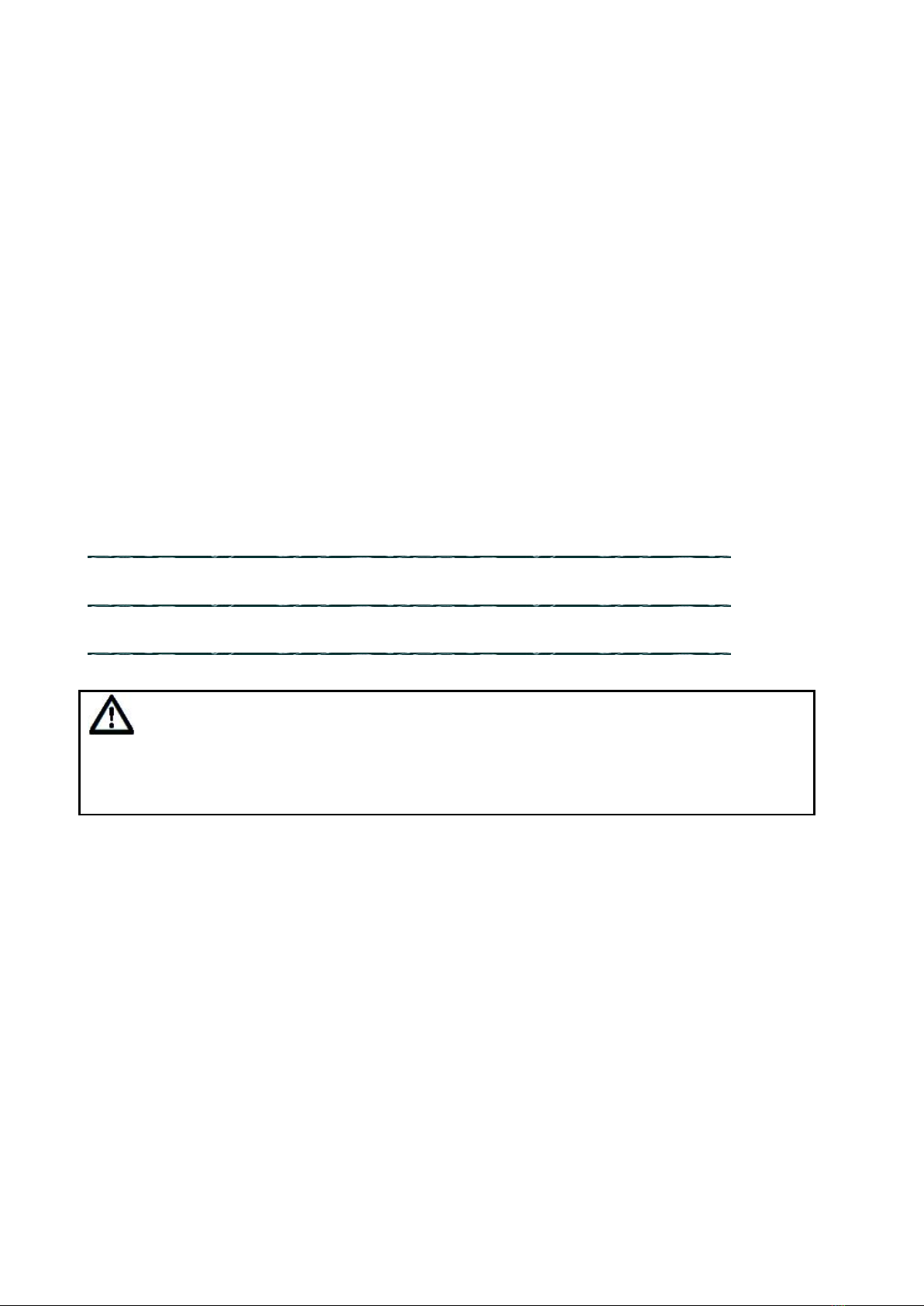
is allowed, in order to restore forward start, disconnect STOP and COM terminal, and then
disconnect FW and COM terminal, reconnect them and forward start is restored. And so on for
backward brake.
XIII. Motor forward and backward limit:
Forward limit Backward limit
Forward limit: LIMIT FW and COM shall be shorted connected, i.e. forward limit.
Backward limit: LIMIT BW and COM shall be shorted connected, i.e. backward limit.
Note: in case of using limit function, need to know the details of logical relationship between
forward & backward start and forward& backward limit.
Control logic:
Firstly, confirm that COM terminal is not shorted connected with LIMIT FW or LIMIT BW, if
required by switch functions, limit direction which is opposite to moving direction shall be selected
for shorted connection.
Back and forth movement of motor:
Supposing that initial position will move forward, firstly, disconnect forward limit and connect
backward limit, and then connect forward start, motor is in direct motion; when it move forward to
certain position, disconnect backward limit, connect forward limit, motor will be immediately
stopped; after this, disconnect forward start, connect backward start, motor is in opposite running,
when it move backward to certain position, disconnect forward limit, connect backward limit, motor
will be immediately stopped. After the completion of above-mentioned actions, a cycle of control
logics has been finished, if repetition is required, above-mentioned control logic need to be
circulated.
XIV. Fault alarm:

Alarm output end
This port is fault alarm output end. It is in high level (DC5V) under working condition and in lower
level (DC0V) under alarm condition.
XV. Connection and description of DC motor:
1. The driver provides motor with voltage by “M1”“M2”terminal blocks.
Note: in case that forward start port is connected on control terminal, however, motor runs in
opposite direction, so the driver shall be disconnected, and then interchange “M1” and “M2” wiring,
motor will be in direct motion.
2. Please confirm that rated voltage of the motor matches well with output voltage of the driver.
XVI. Connection of main power:

WARNING
No reverse polarity protection is provided for power input end of this driver. Storage battery (+)
shall be connected to “IN+” and storage battery (-) shall be connected to “IN-”.
1. As there is no internal fuse, a quick-fused fuse and battery main emergency switch shall be
mounted between power input end and storage battery to protect the driver from emergency power
off when necessary.
(Note: Selection of quick-fused fuse and battery main switch: ratio of rated current value of battery
main switch to rated current value of motor is: 1:3)
Confirm whether the battery voltage can meet driver’s working voltage requirements and whether
battery capacity can bear the load of motor
XVII. Status description of LED indicator light:
Working condition (POWER Green light,STATUS Red light)
Status indicator
Mode description
L1(POWER) Green Light-----Constant light
Electrical connection
L2(STATUS) Red light-----A flicker after powered up
Power on self test
Fault state (POWER Green light,STATUS Red light)
Status indicator
Fault description
L2(STATUS) Red light-----Constant light
Over-current protection
L2(STATUS) Red light-----Quick flashing
Instant over-current

L2(STATUS) Red light-----Four flickers
Over-voltage protection
L2(STATUS) Red light-----a flicker
Temperature protection
XVIII. Description of driver’s protection functions: controller provides overvoltage,
under-voltage, overheat and over-current protection
1. Over voltage, under-voltage protection: when external power supply is higher or lower than
pre-set voltage value threshold, output of controller will be cut off. The range of normal
working voltage is 10-50v. Meanwhile, under-voltage & over voltage value can be set
according to customer’s requirements.
2. Overheat protection: Controller contains an internal temperature detection circuit, when
detected temperature exceeds 80℃, output stage of controller will be fully off.
3. Over-current protection: controller contains an internal current detection circuit, when
detected output current of controller reaches to over-current protection threshold, controller will
enter into over-current protection state.
Note: supposing that driver is under forward start status, when detected working current exceeds the
current threshold, driver will immediately cut off the power stage and stop output. After
troubleshooting, disconnect forward start, connect them again to remove protection.
Jinan Keya Electronic Technology Co., Ltd.
Address: No.78, West Luohe Road, Beiyuan Street, Tianqiao District, Jinan, Shandong, China
250033
Tel: 0531-88975137 88601737 88601217
Fax: 0531-85898028
Website: www.jnky.com
Table of contents
Popular DC Drive manuals by other brands

Rockwell Automation
Rockwell Automation Allen Bradley Kinetix 7000 2099-BM06-S Design guide

HAUTAU
HAUTAU EKA 45-400 Mounting and operating instructions

LUST DRIVETRONICS
LUST DRIVETRONICS FLP Series Service instructions

Aerotech
Aerotech Automation1 iXL2e Hardware manual

Masterflex
Masterflex P/S 850-3010 operating manual

Lenze
Lenze 520 Series Technical description

AOpen
AOpen CD-952E/TKU manual

Parker
Parker Compax3H C3H1xxV4 Series installation manual

ABB
ABB ACS355 series Quick installation guide

Vicon
Vicon V390APT Instructions for installation and operation

Siemens
Siemens PXC00-PE96.A installation instructions

Siemens
Siemens SINAMICS PERFECT HARMONY GH180 Reference manual