KEYES ROSTOK User manual


Guide & Manual for ROSTOK 3D Printer
Content
1. Product manual................................................................................................................................1
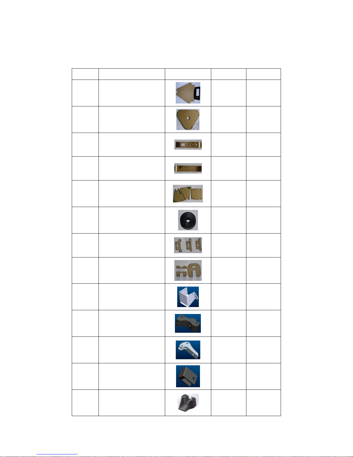
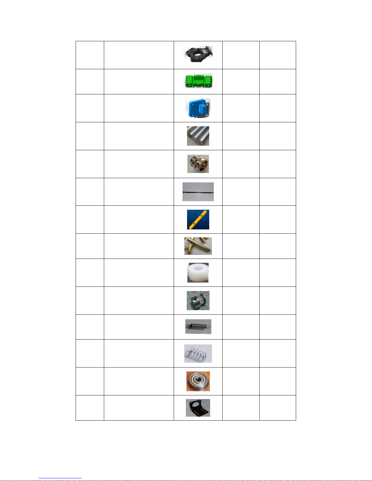
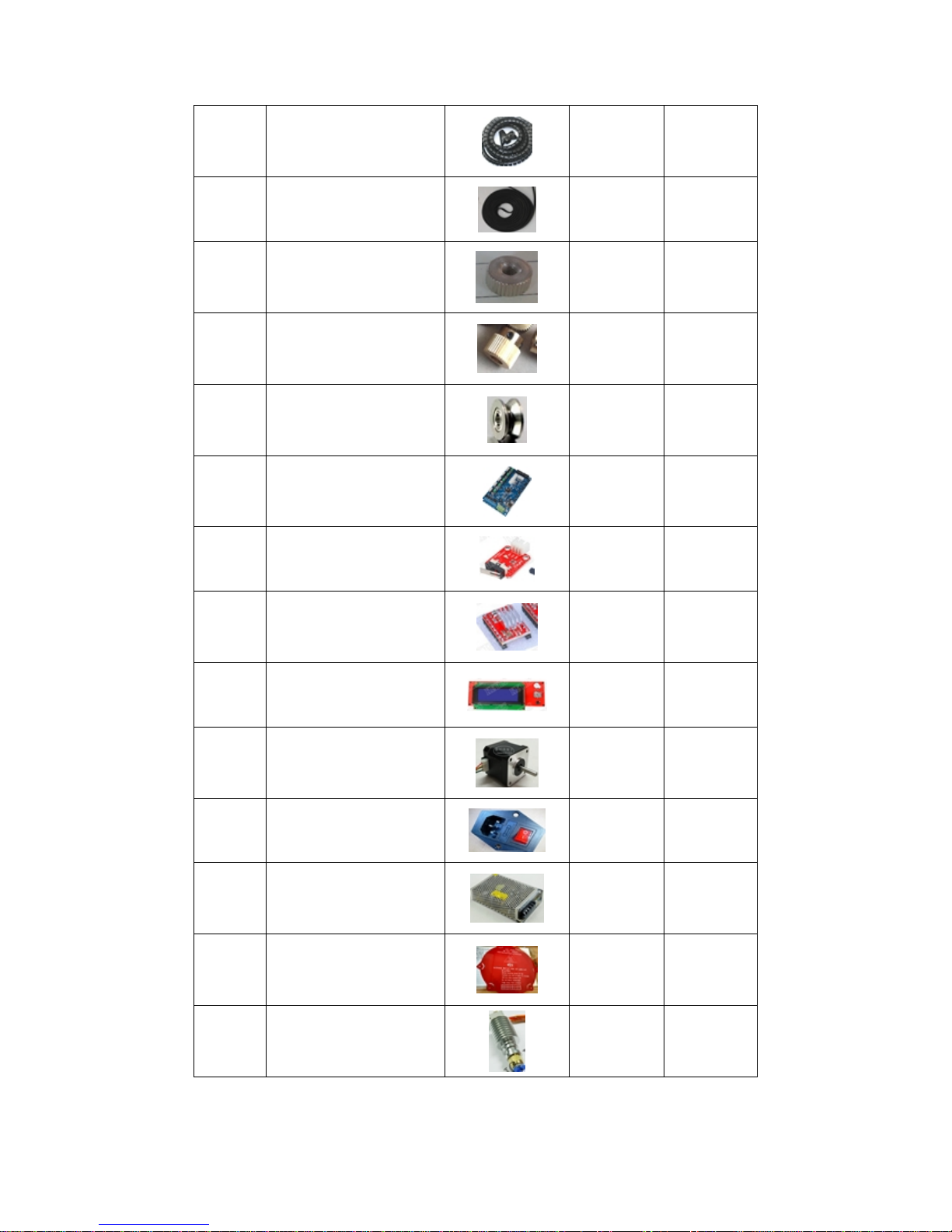
2. BOM................................................................................................................................................4
3. Technical Manual for Installation................................................................................................... 9
I. Installation procedures.............................................................................................................9
1. Installing bottom bracket................................................................................................ 9
2. Installing bottom fixed plate of the frame.................................................................... 10
3. Installing motor............................................................................................................. 12
4. Installing sliding block..................................................................................................14
5. Installing top fixed plate of the frame...........................................................................15
6. Installing power supply.................................................................................................18
7. Installing 3D V1.2 mainboard.......................................................................................19
8. Installing 2004 display.................................................................................................. 21
9. Installing nozzle............................................................................................................ 22
10. Installing hotbed..........................................................................................................23
11. Installing side shield....................................................................................................25
12. Connecting nozzle with sliding block.........................................................................26
13. Installing collision board.............................................................................................27
14. Installing synchronous belt and its regulator.............................................................. 29
15. Installing extruder....................................................................................................... 30
16. Installing material rack................................................................................................32
II. Connecting components:...................................................................................................... 34
4. Connection diagram...................................................................................................................... 37
5. ROSTOK Manual Leveling.......................................................................................................... 37
6. Height adjustment for 3D printer nozzle and hotbed....................................................................46
7. Easy use of Repetier-Host software.............................................................................................. 49
1. Repetier-Host overview........................................................................................................ 49
2. slicing.................................................................................................................................... 56
1)parameter setup for Slic3r...........................................................................................56
2)CuraEngine Settings....................................................................................................66
8. G-code........................................................................................................................................... 72
Content...................................................................................................................................... 73
Introduction............................................................................................................................... 77
RepRap G-code fields............................................................................................................... 78
Comments..................................................................................................................................79
9. LCD Menu details....................................................................................................................... 101

1
1. Product manual
Before you use the printer, please first finish the installation. Before the installation, please
carefully read through manuals of installation, manual leveling etc. After the installation, please
carefully read through the manuals again to check if the printer is correctly installed and correctly
wired. If it is not correctly installed and wired, it may lead to machine malfunction.
Safety note:
Hotbed and nozzle are high temperature parts, do not touch in case of getting burnt.
Power supply part has potential danger, touching may lead to harm.
Attention:
1. For the printer, please prevent contact with water and other liquid. Otherwise, it may lead to
machine damage.
2. When loading the model, please do not turn off the power. Otherwise, it may lead to data loss of
model.
3. During the printer debugging, there will be filament coming out of the nozzle. please make sure
there is at least 50mm distance between the nozzle and the printing platform. Otherwise, it will
lead to nozzle blockage.
4. Normal working temperature of the printer is room temperature, and humidity 20% - 50%.
Exceeding the range can affect forming quality. During the operation of the equipment, there may
be odor in the extrusion process due to material difference. Please keep the air well circulated. If
you feel discomfort, please stop using immediately and seek for corresponding treatment in the
hospital.
5. The SD card supports FAT32 file system. You can store G-Code into it for offline printing.
6. One of the keys to successfully print a model lies in the printing platform. If you are using ABS
material, hotbed platform should be preheated to 90 degrees Celsius, keep the hotbed platform
clean to increase adhesion. If you are using PLA material, you can apply glue (recommend UHU
glue) to the hotbed platform, or preheat hotbed platform to 50 degrees Celsius.
7. During the printing, temperature control of nozzle is also important. If you are using ABS
material, recommended temperature of nozzle is 220-240 degrees Celsius. If you are using PLA
material, recommended temperature of nozzle is 80-210 degrees Celsius. Please set up the
temperature according to material during actual printing.
8. Please note the baud rate is 250000 when connecting the printer to the computer.
9. When you print for the first time, first tighten the nozzle; when the temperature reaches 170
degrees, tighten the nozzle again. In this way, blockage of nozzle will be unlikely. Also, change
the step per mm to 92 as below picture.

2
10. To make the forming quality better, please set up a reasonable printing speed. Higher printing
speed can reduce the printing time, but can result in poor forming quality; lower printing speed
results in longer printing time, but higher forming quality.
11. After using the printer for a period of time, you need to check critical parts such as the
synchronous belt, push rod and screws if they are loosened.
Printer parameters:
Forming size: 140mm*140mm*250mm
Forming principle: FDM (Fused Deposition Modeling)
Material type: 1.75mm ABS or 1.75 PLA
Printing speed: 10-100mm/S
Recommended layer thickness: 0.1-0.3mm
Connection method: USB/SD card
Power supply: AC 110-240V
Software: Repetier-Host
Nozzle: 0.4mm diameter/single nozzle

3
Clearing of fault:
Failure
Solution
Power indicator light out
Check whether the power supply is normal
Whether DC power cord is reversely connected during
installation
Cannot connect to computer
Check whether USB port connection is normal
Check whether USB port corresponds to the software COM
port
Check if software baud rate is set to 250000
Shut off the power and restart the printer
USB cable does not work
Restart the computer
Hotbed cannot reach specified
temperature
Poor connection of temperature sensor
Temperature sensor is damaged, change the sensor
Restart the printer
Nozzle cannot reach specified
temperature
Poor connection of temperature sensor
Temperature sensor is damaged, change the sensor
Restart the printer
Nozzle blockage/ filament
blockage
Clear up the nozzle
Change to a new nozzle
Model deflecting (distorted)
Loose belt, adjust the belt
Motor getting loose from the synchronizing wheel
Poor adhesion between model
and hotbed
Too high distance from nozzle to hotbed
Hotbed temperature does not accord to recommended
temperature of the material
Display showing maximum
temperature
Short circuit of nozzle temperature sensor
Damage of nozzle temperature sensor
Display showing minimum
temperature
Open circuit of nozzle temperature sensor
Damage of nozzle temperature sensor
Display showing maximum
temperature of hotbed
Short circuit of hotbed temperature sensor
Damage of hotbed temperature sensor
Display showing minimum
temperature of hotbed
Open circuit of hotbed temperature sensor
Damage of hotbed temperature sensor

4
2. BOM
No.
Name
Picture
QTY
Unit
1
Top fixed plate of the frame
1
PCS
2
Bottom fixed plate of the
frame
1
PCS
3
Side shield 1
1
PCS
4
Side shield 2
1
PCS
5
Material rack 1
1
Set
6
Hotbed bakelite
6
PCS
7
Collision fixed plate
3
PCS
8
Nozzle fixed plate
1
Set
9
Air-deflecting block
1
PCS
10
Plastic part 1 for extruder
1
Set
11
plastic part 2 for extruder
1
Set
12
Belt regulator
3
PCS
13
Bracket holder
6
PCS

5
14
Movable platform
1
PCS
15
Slider
3
PCS
16
Belt clip
3
PCS
17
Sliding rod
6
PCS
18
Self-lubricating copper bush
6
PCS
19
Push rod
6
PCS
20
45mm copper pillar
6
PCS
21
25mm copper pillar
4
PCS
22
Nylon tube
12
PCS
23
Synchronous wheel
3
PCS
24
Tension spring
3
PCS
25
Spring
1
PCS
26
Flange bearing
6
PCS
27
L-type motor holder
1
PCS

6
28
Winding pipe
1
PCS
29
Synchronous belt
3
PCS
30
Nut
1
PCS
31
Extruder gear
1
PCS
32
V-type bearing
1
PCS
33
3D V1.2
1
PCS
34
Collision board
3
PCS
35
A4988 motor drive board
4
PCS
36
2004 display
1
PCS
37
42 stepper motor
4
PCS
38
Power socket
1
PCS
39
12V switch power supply
1
PCS
40
Hotbed
1
PCS
41
Nozzle
1
PCS

7
42
Teflon hose
1
PCS
43
Pneumatic quick connector
1
PCS
44
2510 cooling fan
1
PCS
45
8025 cooling fan
1
PCS
46
Air blower
1
PCS
47
USB cable
1
PCS
48
USB extension cord
1
PCS
49
Power line
1
PCS
50
Connecting line
2
PCS
51
X axis limit line
1
PCS
52
Y axis limit line
1
PCS
53
Z axis limit line
1
PCS
54
AC power line (short)
1
PCS
55
AC power line (long)
1
PCS

8
56
DC power line (long)
1
PCS
57
Stepper motor power line
(short)
3
PCS
58
Stepper motor power line
(long)
1
PCS
59
Material rack 2
1
PCS
60
Ribbon
20
PCS
61
Adjustable cap
1
PCS
62
M3 screw
a few
PCS
63
M4screw
a few
PCS
64
M3 nut
a few
PCS
65
M4 nut
a few
PCS
66
Self-tapping screw
a few
PCS

9
3. Technical Manual for Installation
I. Installation procedures
ROSTOK 3D printer is easy to install due to its simple hardware structure. Below
are some tips and suggestions for installation.
Before installation, please keep necessary tools on hand. Tools needed are a set of allen
driver for repair, M3, M4 screw tap, nipper pliers, wire stripper and etc. Please be careful
with the pressure you apply during installation in case components were damaged due to
overexertion.
The mechanical structure of the printer is mainly comprised of slider, acrylic board, fixed
units, belt and various attachments. Each component has its own specific installation
position and plays an important role, so please be sure to install in a proper way. You must
also pay close attention to installation procedures. The whole printer structure is not
complicated indeed, but if you don’t follow certain steps, you might risk wasting lots of
precious time. Now let’s move on to specific installation procedures and methods of
ROSTOK 3Dprinter .
1. Installing bottom bracket:
Materials needed are shown in below pic 1:
List:
6pcs Slider
3pcs Bracket holder

10
12pcs M3*14 Hexagon socket head cap screws
12pcs M3 nut
Install as following pic 2 shows: Install slider and softly strike the slider into bracket holder
with small hammer, then screw it down with M3*14 screw. Please mind the pressure you
apply, otherwise, the bracket holder may be broken due to overexertion. Please pay extra
attention to the direction shown in below pictures, the direction must not be taken
conversely. The slider and the bottom of bracket holder must be in one line(as pic 3
shows).
2. Installing bottom fixed plate of the frame:
Materials needed are shown in below pic 4:

11
List:
1pc bottom fixed plate of the frame
12pcs M4*14 screw
12pcs M4 nut
Install as following pic 5&6 shows: Install bottom fixed plate of the frame and screw it down
with screws. Please pay extra attention to the direction of bottom fixed plate of the frame.

12
3. Installing motor:
Materials needed are shown in below pic 7:
List:
3pcs 42 stepper motor
12pcs M3*12 screw
12pcs M3 shim
3pcs synchronous wheel
Install as following pic 8 shows: Install synchronous wheel. Don’t screw it down too tight
because it will be readjusted during belt installation later.
Install as following pic 9 shows: Mount the stepper motor onto bracket holder. Please pay
extra attention to the direction of motor connection ports, it should point at the left or
right of below pic 10 for easy connection.

13

14
4. Installing sliding block:
Materials needed are shown in pic 11:
List:
3pcs Slider
3pcs belt clip
3pcs self-lubricating copper bush
3pcs 45mm copper pillar
3pcs M3*16 screw
6pcs M3*25 screw
6pcs M3*30 screw
12pcs M3 nut
Install as following pic 12 shows: Install self-lubricating copper bush and softly strike it into
slider(the side with chamfer should face down).
Install as following pic 13 shows: Install belt clip and copper pillar, the position pointed out by
red arrow should be screwed down with M3*30 screw; the position pointed out by yellow
arrow should be screwed down with M3*25 screw. Please pay extra attention to the

15
direction of belt clip during installation.
Install as following pic 13 shows: Install one M3*16 screw at the position pointed out by red
arrow in pic 12.
Install as following pic 14 shows: Let the side with leveling screw face up and put slider into it.
The side with belt clip faces the outside of the frame.
5. Installing top fixed plate of the frame:
Material needed are shown in below pic 16:

16
List:
1pc top bracket fixed plate
3pcs bracket holder
12pcs M3*14 screw
12pcs M4*14 screw
12pcs M3 nut
12pcs M4 nut
Install as following pic 17 shows: Install bracket holder onto the slider.
Install as the following pic 18 shows: Install top bracket fixed plate onto bracket holder in the
direction indicated by the arrow in pic 18. The top bracket fixed plate and the slider should be
kept in the same horizontal level.
Install as following pic 19 shows: the part point out by red arrow should be screwed down
with M4*14 screw; the part pointed out by green arrow should be screwed down with M3*14
screw.
Pic 16

17

18
6. Installing power supply:
Materials needed are shown in below pic 20:
List:
1pc switch power supply
4pcs plastic sleeve
4pcs M3*20 screw
Install as following pic 21&22 shows: Install power supply onto top bracket fixed plate in the
direction indicated by pic 21 and screw it down as pic 22 shows.
Table of contents