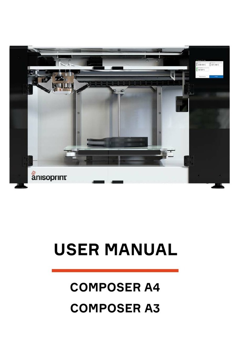
ANISOPRINT COMPOSER A4 User manual

USER MANUAL
COMPOSER A4
COMPOSER A3


TABLE OF CONTENTS
DISCLAIMER 2
SAFETY INSTRUCTIONS 3
COMPLIANCE STATEMENT 5
OVERVIEW 7
BASIC SPECIFICATIONS 7
DELIVERY PACKAGE 8
COMPOSER OPERATIONS 9
MAIN SCREEN 9
INSTALLATION 13
LOADING MATERIALS 13
BUILDPLATE CALIBRATION 13
NETWORK BRIDGE SOFTWARE UPDATING 20
MAINTENANCE 21
PLASTIC NOZZLE REPLACEMENT 21
PLASTIC NOZZLE CLEANING 22
PRINTING MATERIALS 25
PLASTICS 25
SOFTWARE 27
INTERFACE 27
SYSTEM REQUIREMENTS 30

DISCLAMER
This User Manual is the main document for Composer CFC printers, it is provided with the delivery package. The Manual guides
correct operation, maintenance, and troubleshooting of Composer CFC printers manufactured by Anisoprint.
Please follow this User Manual when operating and maintaining the equipment. Failure to follow the guidelines may lead to poor
quality of printed parts, damage to the printer, or cause injury, please read the User Manual carefully.
2anisoprint.comv1.9

SAFETY INSTRUCTIONS
ELECTROMAGNETIC COMPATIBILITY
class A device, which means it can cause additional electromagnetic interference when used at home.
GENERAL PRECAUTIONS
Carefully study all precautions before using the printer. When in operation the user should follow all operation precautions for
electrical equipment.
An explanatory note to graphic symbols:
Basic precautions:
WARNING
RESULT IN SERIOUS INJURY OR FATAL OUTCOME.
CAUTION
RESULT IN MINOR OR MODERATE INJURY.
NOTE
WARNING:
WARNING:
WARNING:
CAUTION:
CAUTION: AVOID PENETRATION OF WATER IN ELECTRONIC COMPONENTS OF
CAUTION:
MAINTENANCE.
CAUTION:
CAUTION:
CAUTION:
AREAS.
NOTE:
NOTE:
NOTE:
NOTE:
MATERIALS ARE REMOVED.
NOTE:
3anisoprint.com
v1.9

PRECAUTIONS WHEN WORKING WITH CARBON FIBER
I
cause splinters.
sure to wear safety glasses and protecting mask.
WARNING SYMBOLS
For reasons of safety the following symbols can be found on the printer case.
WARNING:
AND LABORATORY POWER SUPPLY SOURCES IN ORDER TO AVOID IGNITION
OF CARBON FIBER. CARBON FIBER IS A GOOD ELECTRICAL CONDUCTOR.
WARNING:
AND MAY CAUSE SKIN BURNS
PLACES OF GROUNDING CONNECTIONS
WARNING:
anisoprint.comv1.9

COMPLIANCE STATEMENT
provided the product is not used for anything other than the intended purpose according to the rules and recommendations described
in this User Manual.
NOTE:
CAUTION:
equipment and devices. This equipment must be disposed of in accordance with the applicable local
waste and safety regulations. To ensure safety when disposing the equipment it is necessary to follow
generally accepted practices for safe operation when disposing of equipment and devices.
5anisoprint.com
v1.9

COMPOSITE FIBER COEXTRUSION
is for plastic. The CF goes through central channel and is coated by molten plastics supplied through the lateral channel into the heat
plastics.
The technology allows to use various plastics with processing temperatures up to 270°C. You can use ABS, PLA, PETG, PA, and PC
plastics. The material can be varied to achieve the best operational or economic parameters of the parts depending on the goals.
anisoprint.comv1.9

OVERVIEW
BASIC SPECIFICATIONS
chamber.
provided the product is not used for anything other than the intended purpose according to the rules and recommendations described
in this User Manual.
4 3
Printing technology
P 29 9
Layer thickness, min.
Print head
ter 0.
Print speed for FFF 10 mmsec – 80 mmsec
Print speed for CFC 1 mmsec – 10 mmsec
ter 1.75 mm
Compatible plastics Plastics with processing temperatures up to 27
Reinf Anisoprint CCF
Buildplate surface Glass
TEMPERATURE
Print head operating
temperature, max. 27
Buildplate operating
temperature, max. t
Ambient operating
temperatures
SOFTWARE
Slicer Anisoprint Aura
OS support Windows 7 and later
POWER REQUIREMENTS
Voltage
Frequency 50
Maximum consumption 800 W 1000 W
INTERFACE
LCD 3.5'' touchscreen .3'' touchscreen
Input
PHYSICAL CHARACTERISTICS
Print
Net weight
P
Gross weight
7anisoprint.com
v1.9

DELIVERY PACKAGE
Items in the package:
1. Composer CFC Printer– 1 pc.
2. Plastic filament spool – 2 pc.
3. Anisoprint CCF-1.5k fiber spool – 1 pc.
4. Tool kit – 1 pc.
5. Personal protective equipment kit– 1 pc.
6. Spare parts kit– 1 pc.
7. Memory card SD – 1 pc.
8. User Manual
8anisoprint.comv1.9

COMPOSER OPERATIONS
MAIN SCREEN
After switching on the Composer printer, you will see the main screen, which brief description is given below.
1 – Plastic extruder temperature settings button
2 – Buildplate temperature settings button
3 – Composite extruder temperature settings button
C – Printer connection settings
9anisoprint.com
v1.9

Also, you can control material supply. To do it press Extruders
Use axes movement control buttons to move by axes Select movement increment
Use home positioning buttons for tool homing
buildplate
10 anisoprint.comv1.9

F – Printer settings button.
Control material feed coordinates Change active extruder
NOTE:
11anisoprint.com
v1.9

12 anisoprint.comv1.9

INSTALLATION
Your Composer requires several assembly steps before you can start printing.
for any unevenness of the surface if needed.
1. Remove blue transportation tape to release the doors and print head
3. Using a hex key from the Tool kit, attach the spool holders to the back mount of the printer
may vary with the printer model
13anisoprint.com
v1.9

5. Plug in the power cable
Buildplate
LOADING MATERIALS
NOTICE: Plastic can leak out of the composite heat block inlet during plastic filament loading in the composite extruder. Just
remove the leaked plastic with tweezers to prevent dripping of the plastic on the printed part.
BUILDPLATE CALIBRATION
may need to go through the entire calibration procedure after the printer installation.
NOTICE: Clean and preheat the nozzles and the buildplate to its printing temperatures before all the calibration procedures
(buildplate, Z axis, Z-offset) to prevent incorrect calibration.
You need to go through the buildplate calibration procedure after any changes affecting the positioning of the buildplate, e.g.
shaking or moving the printer. While printing a large part occupying the whole buildplate area, you can notice layer thickness varies
from one end of the part to another, which as well means the buildplate requires recalibration.
the left and right corners are tuned manually by adjusting the regulation screws. Second, the procedure is to be repeated for
must be sliding in the gap with a slight friction.
It is recommended to calibrate the Z axis right after the buildplate calibration.
onto the holders.
2. On the Composer screen, click
and choose the material
you want to load. Follow instructions on the screen.
anisoprint.comv1.9

Z AXIS CALIBRATION
layer of the print.
Press
Z-OFFSET CALIBRATION
due to improper plastic layup, go through this procedure. Also, it is recommended to go through this procedure every time you replace
On the screen of the printer, press
procedure by following the instructions on the screen.
15anisoprint.com
v1.9

XY OFFSETS CALIBRATION
shown in the picture below.
You can also download it from
To change these values, go to
middle of the central cells, like it is shown in the scheme below:
central cells, like it is shown in the reference scheme below, you
anisoprint.comv1.9

central cells.
TEST PRINT
• After the print start, both extruders, plastic and composite, start to heat. When the composite extruder reaches the extrusion
surface and look smooth and uniform
• Inspect the printed part paying special attention to side walls quality. Check the surface smoothness visually and compare to
1 – Fiber perimeters
3 – Outer plastic perimeters
17anisoprint.com
v1.9

IN-SITU TUNING OF PRINTING SETTINGS
Some basic operations with the printer are still available during the printing.
process pressing CONTROL button.
After the print is paused, the print head and buildplate will return to its default positions. Extruders stay hot during the pause. You
can see all the control capabilities over the paused print at the picture below.
1 — Cancel the print
2 — Cool or heat up extruders and buildplate
18 anisoprint.comv1.9
Other manuals for COMPOSER A4
1
This manual suits for next models
1
Table of contents
Other ANISOPRINT 3D Printer manuals