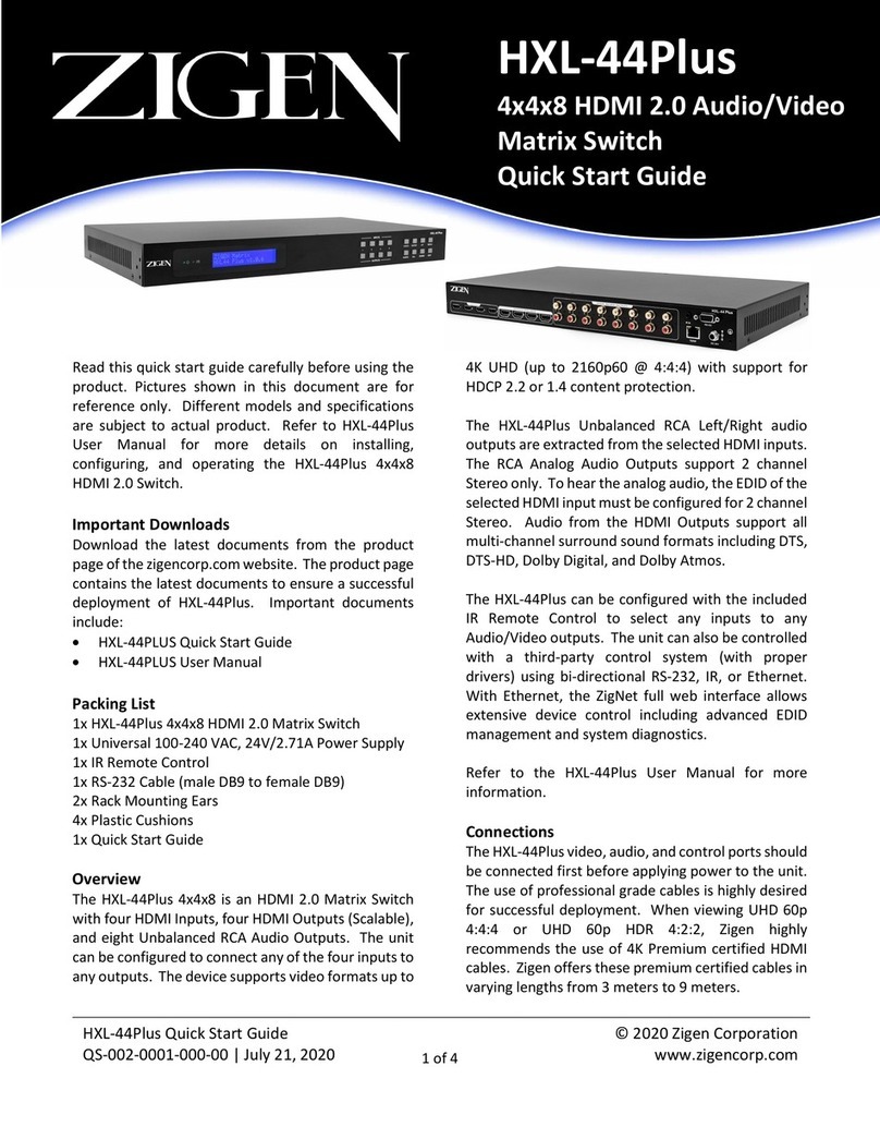
Keysight Technologies U3020AH37 Manual

User’s and
Service Guide
Keysight Technologies
U3020AH37
Notice: This document contains references to
Agilent. Please note that Agilent’s Test and
Measurement business has become Keysight
Technologies. For more information, go to
www.keysight.com.

Notices
© Keysight Technologies, Inc. 2017
No part of this manual may be
reproduced in any form or by any
means (including electronic storage
and retrieval or translation into a
foreign language) without prior
agreement and written consent
from Keysight Technologies, Inc. as
governed by United States and
international copyright laws.
Trademark
Acknowledgments
Manual Part Number
U3020-90017
Edition
Edition 1, February 2017
Supersedes: None
Printed in USA/Malaysia
Published by:
Keysight Technologies
1400 Fountaingrove Parkway Santa
Rosa, CA 95403
Warranty
THE MATERIAL CONTAINED IN
THIS DOCUMENT IS PROVIDED “AS
IS,” AND IS SUBJECT TO BEING
CHANGED, WITHOUT NOTICE, IN
FUTURE EDITIONS. FURTHER, TO
THE MAXIMUM EXTENT PERMITTED
BY APPLICABLE LAW, KEYSIGHT
DISCLAIMS ALL WARRANTIES,
EITHER EXPRESS OR IMPLIED WITH
REGARD TO THIS MANUAL AND
ANY INFORMATION CONTAINED
HEREIN, INCLUDING BUT NOT
LIMITED TO THE IMPLIED
WARRANTIES OF
MERCHANTABILITY AND FITNESS
FOR A PARTICULAR PURPOSE.
KEYSIGHT SHALL NOT BE LIABLE
FOR ERRORS OR FOR INCIDENTAL
OR CONSEQUENTIAL DAMAGES IN
CONNECTION WITH THE
FURNISHING, USE, OR
PERFORMANCE OF THIS
DOCUMENT OR ANY INFORMATION
CONTAINED HEREIN. SHOULD
KEYSIGHT AND THE USER HAVE A
SEPARATE WRITTEN AGREEMENT
WITH WARRANTY TERMS
COVERING THE MATERIAL IN THIS
DOCUMENT THAT CONFLICT WITH
THESE TERMS, THE WARRANTY
TERMS IN THE SEPARATE
AGREEMENT WILL CONTROL.
Technology Licenses
The hardware and/or software
described in this document are
furnished under a license and may be
used or copied only in accordance
with the terms of such license.
U.S. Government Rights
The Software is “commercial
computer software,” as defined
by Federal Acquisition Regulation
(“FAR”) 2.101. Pursuant to FAR
12.212 and 27.405-3 and
Department of Defense FAR
Supplement (“DFARS”) 227.7202,
the U.S. government acquires
commercial computer software
under the same terms by which
the software is customarily
provided to the public.
Accordingly, Keysight provides
the Software to U.S. government
customers under its standard
commercial license, which is
embodied in its End User License
Agreement (EULA), a copy of
which can be found at
http://www.keysight.com/find/
sweula The license set forth in
the EULA represents the
exclusive authority by which the
U.S. government may use,
modify, distribute, or disclose the
Software. The EULA and the
license set forth therein, does
not require or permit, among
other things, that Keysight: (1)
Furnish technical information
related to commercial computer
software or commercial
computer software
documentation that is not
customarily provided to the
public; or (2) Relinquish to, or
otherwise provide, the
government rights in excess of
these rights customarily provided
to the public to use, modify,
reproduce, release, perform,
display, or disclose commercial
computer software or
commercial computer software
documentation. No additional
government requirements
beyond those set forth in the
EULA shall apply, except to the
extent that those terms, rights, or
licenses are explicitly required
from all providers of commercial
computer software pursuant to
the FAR and the DFARS and are
set forth specifically in writing
elsewhere in the EULA. Keysight
shall be under no obligation to
update, revise or otherwise
modify the Software. With
respect to any technical data as
defined by FAR 2.101, pursuant
to FAR 12.211 and 27.404.2 and
DFARS 227.7102, the U.S.
government acquires no greater
than Limited Rights as defined in
FAR 27.401 or DFAR 227.7103-5
(c), as applicable in any technical
data.
Safety Notices
A CAUTION notice denotes a hazard.
It calls attention to an operating
procedure, practice, or the like that,
if not correctly performed or adhered
to, could result in damage to the
product or loss of important data. Do
not proceed beyond a CAUTION
notice until the indicated conditions
are fully understood and met.
A WARNING notice denotes a hazard.
It calls attention to an operating
procedure, practice, or the like that,
if not correctly performed or adhered
to, could result in personal injury or
death. Do not proceed beyond a
WARNING notice until the indicated
conditions are fully understood and
met.

Contents-1
Table of Contents
U3020AH37
Description. . . . . . . . . . . . . . . . . . . . . . . . . . . . . . . . . . . . . . . . . . . . . . . . . . . . . . . . . . . . . . . . 1
Verifying the Shipment . . . . . . . . . . . . . . . . . . . . . . . . . . . . . . . . . . . . . . . . . . . . . . . . . . . . . . 2
Available Options . . . . . . . . . . . . . . . . . . . . . . . . . . . . . . . . . . . . . . . . . . . . . . . . . . . . . . . . . .2
General Performance. . . . . . . . . . . . . . . . . . . . . . . . . . . . . . . . . . . . . . . . . . . . . . . . . . . . . . . . 3
Dimensions and Space Requirements . . . . . . . . . . . . . . . . . . . . . . . . . . . . . . . . . . . . . . . 3
General RF Switch Specifications. . . . . . . . . . . . . . . . . . . . . . . . . . . . . . . . . . . . . . . . . . . 3
RF Channel Performance . . . . . . . . . . . . . . . . . . . . . . . . . . . . . . . . . . . . . . . . . . . . . . . . . 4
Front and Rear Panel Features . . . . . . . . . . . . . . . . . . . . . . . . . . . . . . . . . . . . . . . . . . . . . . . . 6
Controlling the Test Set . . . . . . . . . . . . . . . . . . . . . . . . . . . . . . . . . . . . . . . . . . . . . . . . . . . . 10
Controlling the Test Set and Making Measurements. . . . . . . . . . . . . . . . . . . . . . . . . . . 10
LAN Connection Using Your Company’s Internet. . . . . . . . . . . . . . . . . . . . . . . . . . . . . . 10
Test Set Control Commands. . . . . . . . . . . . . . . . . . . . . . . . . . . . . . . . . . . . . . . . . . . . . . 11
Operation Verification. . . . . . . . . . . . . . . . . . . . . . . . . . . . . . . . . . . . . . . . . . . . . . . . . . . . . . 13
Equipment Required . . . . . . . . . . . . . . . . . . . . . . . . . . . . . . . . . . . . . . . . . . . . . . . . . . . . 13
Equipment Setup . . . . . . . . . . . . . . . . . . . . . . . . . . . . . . . . . . . . . . . . . . . . . . . . . . . . . . 13
Measurement Setup . . . . . . . . . . . . . . . . . . . . . . . . . . . . . . . . . . . . . . . . . . . . . . . . . . . . 14
Switched Receiver and Source Signal Path Checks. . . . . . . . . . . . . . . . . . . . . . . . . . . . 14
Thru-Path Receiver and Source Signal Path Checks . . . . . . . . . . . . . . . . . . . . . . . . . . . 14
Service Information . . . . . . . . . . . . . . . . . . . . . . . . . . . . . . . . . . . . . . . . . . . . . . . . . . . . . . . . 16
Electrostatic Discharge Protection . . . . . . . . . . . . . . . . . . . . . . . . . . . . . . . . . . . . . . . . . 17
Theory of Operation . . . . . . . . . . . . . . . . . . . . . . . . . . . . . . . . . . . . . . . . . . . . . . . . . . . . 18
Key Test Set Components. . . . . . . . . . . . . . . . . . . . . . . . . . . . . . . . . . . . . . . . . . . . . 18
Controller Module and Power Supply. . . . . . . . . . . . . . . . . . . . . . . . . . . . . . . . . . . . 20
39495EXT Module. . . . . . . . . . . . . . . . . . . . . . . . . . . . . . . . . . . . . . . . . . . . . . . . . . . 20
Distribution Board . . . . . . . . . . . . . . . . . . . . . . . . . . . . . . . . . . . . . . . . . . . . . . . . . . . 20
Power Divider . . . . . . . . . . . . . . . . . . . . . . . . . . . . . . . . . . . . . . . . . . . . . . . . . . . . . . 20
Power Amplifier . . . . . . . . . . . . . . . . . . . . . . . . . . . . . . . . . . . . . . . . . . . . . . . . . . . . . 20
Troubleshooting . . . . . . . . . . . . . . . . . . . . . . . . . . . . . . . . . . . . . . . . . . . . . . . . . . . . . . . 21
Front Panel Instrument State LEDs . . . . . . . . . . . . . . . . . . . . . . . . . . . . . . . . . . . . . 21
RF Switch is Not Switching . . . . . . . . . . . . . . . . . . . . . . . . . . . . . . . . . . . . . . . . . . . .22
Internal Component Views. . . . . . . . . . . . . . . . . . . . . . . . . . . . . . . . . . . . . . . . . . . . .23

Contents-2
Table of Contents
Measurement System Configuration. . . . . . . . . . . . . . . . . . . . . . . . . . . . . . . . . . . . . . . . . .27
RF Interface Cable Connections, 14-Port System . . . . . . . . . . . . . . . . . . . . . . . . . . . .28
RF Cable Connection Procedure. . . . . . . . . . . . . . . . . . . . . . . . . . . . . . . . . . . . . . . . . .29
RF Interface Cable Connections, 24-Port System . . . . . . . . . . . . . . . . . . . . . . . . . . . .31
Instrument Settings. . . . . . . . . . . . . . . . . . . . . . . . . . . . . . . . . . . . . . . . . . . . . . . . . . . . . . .34
Keysight Connection Expert Usage . . . . . . . . . . . . . . . . . . . . . . . . . . . . . . . . . . . . . . .34
Configuring the LAN Interface . . . . . . . . . . . . . . . . . . . . . . . . . . . . . . . . . . . . . . . .34
Locating the Instrument . . . . . . . . . . . . . . . . . . . . . . . . . . . . . . . . . . . . . . . . . . . . . . . .34
Configuring the GPIB Interface.. . . . . . . . . . . . . . . . . . . . . . . . . . . . . . . . . . . . . . .36
Adding Instruments to the GPIB Configuration . . . . . . . . . . . . . . . . . . . . . . . . . . .36
Changing the GPIB Address . . . . . . . . . . . . . . . . . . . . . . . . . . . . . . . . . . . . . . . . . .36
LAN and GPIB Configuration Commands. . . . . . . . . . . . . . . . . . . . . . . . . . . . . . . . . . .37
IP Address Command . . . . . . . . . . . . . . . . . . . . . . . . . . . . . . . . . . . . . . . . . . . . . . .37
Auto IP Address Command . . . . . . . . . . . . . . . . . . . . . . . . . . . . . . . . . . . . . . . . . . .37
DHCP Command . . . . . . . . . . . . . . . . . . . . . . . . . . . . . . . . . . . . . . . . . . . . . . . . . . .38
DNS Command . . . . . . . . . . . . . . . . . . . . . . . . . . . . . . . . . . . . . . . . . . . . . . . . . . . .38
Domain Name Command . . . . . . . . . . . . . . . . . . . . . . . . . . . . . . . . . . . . . . . . . . . .39
Gateway Address Command. . . . . . . . . . . . . . . . . . . . . . . . . . . . . . . . . . . . . . . . . .39
Host Name Command. . . . . . . . . . . . . . . . . . . . . . . . . . . . . . . . . . . . . . . . . . . . . . .40
GPIB Address Command . . . . . . . . . . . . . . . . . . . . . . . . . . . . . . . . . . . . . . . . . . . . .40
Safety and Regulatory Information . . . . . . . . . . . . . . . . . . . . . . . . . . . . . . . . . . . . . . . . . . .41
Introduction . . . . . . . . . . . . . . . . . . . . . . . . . . . . . . . . . . . . . . . . . . . . . . . . . . . . . . . . . .41
Safety Earth Ground . . . . . . . . . . . . . . . . . . . . . . . . . . . . . . . . . . . . . . . . . . . . . . . . . . .41
Declaration of Conformity. . . . . . . . . . . . . . . . . . . . . . . . . . . . . . . . . . . . . . . . . . . . . . .41
Safety. . . . . . . . . . . . . . . . . . . . . . . . . . . . . . . . . . . . . . . . . . . . . . . . . . . . . . . . . . . . .. .41
Before Applying Power . . . . . . . . . . . . . . . . . . . . . . . . . . . . . . . . . . . . . . . . . . . . . . . . .42
Connector Care and Cleaning Precautions. . . . . . . . . . . . . . . . . . . . . . . . . . . . . . . . . .43
Regulatory Information . . . . . . . . . . . . . . . . . . . . . . . . . . . . . . . . . . . . . . . . . . . . . . . . . . . .45
Instrument Markings . . . . . . . . . . . . . . . . . . . . . . . . . . . . . . . . . . . . . . . . . . . . . . . . . . 45
Keysight Support, Services, and Assistance . . . . . . . . . . . . . . . . . . . . . . . . . . . . . . . . . . . 46
Service and Support Options.. . . . . . . . . . . . . . . . . . . . . . . . . . . . . . . . . . . . . . . . . . . 46
Contacting Keysight. . . . . . . . . . . . . . . . . . . . . . . . . . . . . . . . . . . . . . . . . . . . . . . . . . . 46
Shipping Your Product to Keysight for Service or Repair . . . . . . . . . . . . . . . . . . . . . . 46

U3020AH37

1-
Description
Figure 1
U3020AH37
Description
The Keysight U3020AH37 is a Switch Matrix that allows a Keysight PNA-X N5241/2A
and U3022B10 10-Port Test Set to be configured into an enhanced measurement
system.
Measurement system information can be found on page 27.
The Keysight U3020AH37 has the following key features:
— Low loss mechanical RF switching.
— Test Set control is processed via the LAN or GPIB rear panel interface.
— A standard Keysight System II instrument cabinet (4EIA height x 497.8 mm depth).
— Added High Power amplifier in the PNA-X Port 3 Source Path.
— Selectable PNA-X Receiver signal for external Spectrum Analyzer monitoring.
The Keysight U3020AH37 will be referred to as the Test Set throughout this
document.
U3020AH37
1
Keysight U3020AH37 User's and Service Guide

U3020AH37
Verifying the Shipment
Verifying the Shipment
To verify the contents shipped with your product, refer to the “Box Content
List” included with the shipment.
Inspect the shipping container. If the container or packing material is
damaged, it should be kept until the contents of the shipment have been
checked mechanically and electrically. If there is physical damage refer to
“Contacting Keysight” on page 46. Keep the damaged shipping materials
(if any) for inspection by the carrier and an Keysight Technologies
representative.
Table 1 U3020AH37 Accessories Supplied
Description Part Number
RF Cable, Semi-Rigid, ECAL Module Bypass U3020-20401
User's and Service Guide, U3020AH37 U3020-90017
1
RF Cable, Semi-Rigid, PNA-X to Test Set Interface U3022-20214
Quantity
RF Cable, Semi-Rigid, PNA-X to Test Set Interface
1
24
Available Options
Test Set Options
The Test Set has one available option:
— Option 700 (Standard)
Rack Mounting Kits
Installation instructions are included in the option package.
— U3020AH37-1CM, Rack Mount Kit without Handles (5063-9215)
— U3020AH37-1CN, Front Handle Kit (5063-9228)
— U3020AH37-1CP, Rack Mount Kit with Handles (5063-9222)
RF Cable, Semi-Rigid, ECAL Module Interface U3042-20076 1
Refer to the "Measurement System Configuration" section for PNA-X
interface cable applications.
2
U3022-20213
Keysight U3020AH37 User's and Service Guide
2

U3020AH37
General Performance
1-
General Performance
The Test Set performance is specified for a standalone instrument.
This product has an autoranging line voltage input. Be sure the supply
voltage is within the specified range.
Dimensions and Space Requirements
General RF Switch Specifications
Table 2 Test Set Dimensions
Item Length/Weight
Width 42.5 cm (16.73 in)
Depth 57.4 cm (23 in)
Height 17.7 cm (7 in)
Weight 10.5 kg (23 lb)
Table 3 Internal RF Switch and Key Parameters
Maximum Input Power Rating 1 Watt (+30 dBm) average
into 50 Ohm internal loads.
Switch Life 5 million cycles minimum
Standard installation of the U3020AH37 includes configuration and
installation on a customer provided lab bench, or table top of adequate
size and strength.
3
Keysight U3020AH37 User's and Service Guide

U3020AH37
General Performance
1-
RF Channel Performance
Table 4 Typical Performance Characteristics
Frequency Range Limits (dB)
Insertion Loss, Non-Switched CPLR THRU & CPLR ARM Paths (≤ dB)
10 MHz to 1GHz 0.4
10MHz to 1GHz 1.0
1 GHz to 5GHz 1.5
5 GHz to 10 GHz
10GHz to 18 GHz 2.5
1GHz to 5 GHz 0.5
5GHz to 10 GHz 0.7
10 GHz to 18 GHz 1.0
18 GHz to 26.5 GHz 1.5
18 GHz to 26.5 GHz 4.0
2.0
10MHz to 1GHz 7.5
Comment
Insertion Loss, Switched Source Out & RCVR C/B IN Paths (≤ dB)
Insertion Loss, Switched RCVR B/C IN to Spectrum Analyzer Port Paths (≤ dB)
1GHz to 5 GHz 8.0
5GHz to 10 GHz 9.5
10 GHz to 18 GHz 10
18 GHz to 26.5 GHz 12
Insertion Loss, Switched RCVR A/D IN Paths (≤ dB)
10MHz to 1GHz 7.5
1GHz to 5 GHz 8.0
5GHz to 10 GHz 9.5
10 GHz to 18 GHz 10
Typical RF Channel Performance parameter values are based on one
or two units performance and are intended as non-warrantied
information (see Table 4 below).
Keysight U3020AH37 User's and Service Guide
4

U3020AH37
General Performance
1-
RF Channel Performance
Table 4 Typical Performance Characteristics (Continued)
Frequency Range Limits (dB)
Insertion Loss, Switched RCVR A/D IN to Spectrum Analyzer Port Paths (≤ dB)
10 MHz to 1GHz 14
10MHz to 5GHz 15
15
5 GHz to 10 GHz
10GHz to 18 GHz
7
1GHz to 5 GHz 15
5GHz to 10 GHz 15.75
10 GHz to 18 GHz 17
18 GHz to 26.5 GHz
12
10MHz to 26.5 GHz 80
Comment
Port Return Loss, 18 GHz Max. for RCVR A/D/R3 IN, CPLR THRU (Port 3) (< - dB)
Isolation, Channel (Non-Active Amplifier Channel) (> dB)
RF Amplifier (0.7 GHz to 18 GHz)
Output @ -10 dBm, 8 to 12 GHz
(Typical)
11 - 14 dBm
Power Out @ 1 dB Compress
(Typical)
24 dBm
Max. CW Input
Gain (Typical)
1GHz to 18 GHz 60
Isolation, Channel (Active Amplifier Channel) (> dB)
Port 3 Group Test Set - CPLR THRU
Noise Figure (Typical)
4 dBm
26 dB
3.0
CPLR THRU Port (In/Out)
5
Keysight U3020AH37 User's and Service Guide

U3020AH37
Front and Rear Panel Features
Front and Rear Panel Features
Refer to the standard instrument documentation for damage limits to the
ports. Verify that your test setup will not cause those limits to be exceeded.
LAN Reset
The LAN reset button restores the instrument's default LAN configuration.
Instrument State LEDs
When the power is applied to the Test Set, the instrument enters its power-
on sequence which requires several seconds to complete. The LEDs provide
information on the state of the instrument during power-on and upgrades of
the instrument firmware. Table 5 identifies the instrument states based on
the color and functioning of the LEDs.
Standby Switch
Note that this switch is Standby only, not a line switch. The main power cord
can be used as the system disconnecting device. It disconnects the mains
circuits from the mains supply.
PNA-X and Test Set Signal Access Ports
These sixteen ports are used to interface the Source and Receiver signal
paths for a 4-Port PNA-X. Nine of these ports can be redirected by internal
RF transfer switches for enhanced user measurement capabilities. The
remaining seven access ports are "Passed Thru" to the lower Test Set #2
access ports. Each group of four access ports are associated with and in
alignment with the PNA-X Test Ports 1, 3, 4, and 2, as shown in Figure 2.
Figure 2 Front Panel
Standby
Switch
LAN Reset
Instrument State LEDs TESTSET #2 Access Ports (x16)
ECAL
Module
Access
Ports
PNA-X Signal Access Ports (x16)
Port 1 Port 2
Port 3 Port 4
*
(Note: the access ports marked with * are "switched" for measurement flexibility.)
*
**
*
*
R3 Mxr Access Ports (2)
Spectrum Analyzer Port
Keysight U3020AH37 User's and Service Guide
6
*
*
*
*
*

U3020AH37
Front and Rear Panel Features
ECAL Module Access Ports
These two ports provide a permanent connection on a Keysight N4691B
ECAL Module. An interface semi-rigid cable (U3042-20076) is provided in
order to connect the second module port to the SOURCE IN ECAL access
port. The SOURCE IN ECAL access port, by use of the internal transfer
switches, can be redirected to the SOURCE OUT Test Set access port for
PNA-X Source Port 1 or 3.
R3 Mixer Access Ports
These two ports, RCVR R3 IN and SOURCE OUT, are provided for the
High Powered signal mode available for the PNA-X Port 3 source
channel.
Spectrum Analyzer Port
This port is made available to monitor any one of the RCVR A/B/C/D
signals.
Figure 3 ECAL Module Connected to ECAL Port B Access Port
ECAL Module
7
Keysight U3020AH37 User's and Service Guide

Figure 4 Rear Panel
GPIB LAN Line Input
GPIB Connector
This connector allows the Test Set to be connected directly to a controller.
Factory set address = 26.
LAN
The instrument is controlled over Local Area Network (LAN).
Line Input
The line input contains the power cord receptacle.
Install the instrument so that the detachable power cord is readily identifiable
and is easily reached by the operator. The detachable power cord is the
instrument disconnecting device. It disconnects the mains circuits from the
mains supply before other parts of the instrument. The front panel switch is
only a standby switch and is not a LINE switch. Alternatively, an externally
installed switch or circuit breaker (which is readily identifiable and is easily
reached by the operator) may be used as a disconnecting device.
U3020AH37
Front and Rear Panel Features
Keysight U3020AH37 User's and Service Guide
8

1-
Table 5
LED Color Instrument State
ATTN
LAN
PWR
Off
Green
Green
Instrument in “ready” state
LAN connection established
- instrument has an IP address firmware download complete
ATTN
LAN
PWR
flashing
flashing
Green
Power-on/boot-up. ATTN and LAN will flash red and then green during the
power-on self-test.
ATTN
LAN
PWR
Off
Red
Green
No LAN connection due to:
- disconnected LAN cable
- failure to acquire and IP address
- waiting for DHCP-assigned address
ATTN
LAN
PWR
Green (flashing)
Green
Green
Instrument Busy State
- firmware download (LAN LED red if download over GPIB)
- lengthy instrument operation in progress
ATTN
LAN
PWR
Red (flashing)
Green
Green
Instrument programming error or self-test error.
Error queue is read using SYSTem:ERRor?
ATTN
LAN
PWR
Off
Green (flashing)
Green
Instrument identification. Activated from instrument Web interface:
ON: Turn on Front Panel Interface Indicator
OFF: Turn off Front Panel Interface Indicator
U3020AH37
Front and Rear Panel Features
Instrument State LED Definitions
Always use the three-prong AC power cord supplied with this product. Failure
to ensure adequate grounding by not using this cord may cause damage to
the product.
9
Keysight U3020AH37 User's and Service Guide

U3020AH37
Controlling the Test Set
1-
Controlling the Test Set
Controlling the Test Set and Making Measurements
The Keysight U3020A is a “slave” instrument. A controller must be used to
control the Test Set. There are two methods that can be used to control the
Test Set.
—Using LAN connection
— Using GPIB connection
Once the connection between the Controller and the Test Set has been
established (LAN or GPIB), the Test Set can be controlled using SCPI
commands.
LAN Connection using Your Company’s Intranet
Connect the Test Set and your controlling computer to an active instrument
LAN line. Open the Internet browser application on the computer. Enter this
default web address on your browser application: http://U3020AH37-xxxx
1. Browser Web Connect (control button on the left side of the screen)
2. Allow Full control
3. Sequences (refer to Table 6)
The last four digits in the web address (xxxx) are the last four digits of the
instruments serial number.
Once the connection between the controller and the Test Set has
been established (LAN or GPIB), the Test Set can be controlled using
SCPI commands. Refer to Table 6 on page 11.
The Welcome screen for the instrument should be viewable if the LAN connection
is working. Select the following screen control buttons to access the SCPI
command control window:
The computer used must have Java installed to access the "Allow Full
Control" feature. Java version 7 or below is needed. Any security block
due to the instrument web address can be bypassed by adding a web
exception to Java. In the Java Control Panel, select the Security tab, then
click on the Edit Site List button. In the Edit Site List window, enter the
instrument web address.
Keysight U3020AH37 User's and Service Guide
10

U3020AH37
Controlling the Test Set
Test Set Control Commands
The Test Set has predefine sequence command sets defined at the factory
and stored in the non-volatile memory of the controller module. If the
specified sequence name is not currently stored in the memory, due to
corrupted program or accidentally deleted, an error will be generated. Refer
to the Service section of this manual for instructions to remedy this issue.
Syntax:
ROUTe:SEQuence:TRIGger <command>
Example: The executable sequence "ALLTHRU" will set the internal switches
to standard pass thru mode:
ROUT:SEQ:TRIG ALLTHRU
Parameters:
Refer to Table 6 below for commands use to control the Test Set’s
programmable switches.
Table 6 Test Set Control Commands
No. SCPI
Command
Connection Path
Description
Comments
1ALLTHRU Set all SCR and RCVR to Norm (Thru Path Mode) Disables ECAL, SA signal, and High Power signal to R3
2ECAL ECAL Access Ports into PNAx SRC1 Path ECAL Mode (S1)
3ECAL_NO Bypass ECAL Access Ports Non-ECAL Mode (S1)
4R3IN_NORM R3 IN to PNAx SRC OUT PNAx MXR R3 INPUT Select - Normal Mode (S8)
5R3IN_HIPWR R3 IN to Test Set CPLR THRU
6RCVR_AD_NORM RCVR A & D IN Paths are Normal (Thru Path Mode)
7RCVR_AD_REV RCVR A & D IN Paths are Reversed (Rev Path Mode)
PNAx MXR R3 INPUT Select - High Power Mode (S8)
TS1 A & TS2 D IN to PNAx Rec A & D IN (S5)
TS1 A & TS2 D IN to PNAx Rec D & A IN (S5)
8RCVR_BC_NORM RCVR B & C IN Paths are Normal (Thru Path Mode) TS1 B & TS2 C IN to PNAx Rec B & C IN (S4)
9RCVR_BC_REV RCVR B & C IN Paths are Reversed (Rev Path Mode) TS1 B & TS2 C IN to PNAx Rec C & B IN (S4)
10 SA_ADIN Test Set RCVR A or D IN signal to Spec Analyzer Port TS1 RCVR A or TS2 RCVR D IN Not to Spec Analyzer Port (S7)
11 SA_ADIN_NO RCVR A or D IN Paths are Normal (Thru Path Mode) TS1 RCVR A or TS2 RCVR D IN Paths in Normal Mode (S7)
12 SA_AIN TS1 RCVR A IN signal to Spec Analyzer Port
13 SA_AIN_NO TS1 RCVR A IN Path is Normal (Thru Path Mode)
14 SA_BCIN Test Set RCVR B or C IN signal to Spec Analyzer Port
Combines RCVR_AD_NORM & SA_ADIN (S5, S7)
Combines RCVR_AD_NORM & SA_ADIN_NO (S5, S7)
TS1 RCVR B or TS2 RCVR C IN Not to Spec Analyzer Port (S6)
11
Keysight U3020AH37 User's and Service Guide

U3020AH37
Controlling the Test Set
Table 6 Test Set Control Commands (Continued)
No. SCPI
Command
Connection Path
Description
Comments
15 SA_BCIN_NO RCVR B or C IN Paths are Normal (Thru Path Mode) TS1 RCVR B or TS2 RCVR C IN Paths in Normal Mode (S6)
16 SA_BIN TS1 RCVR B IN signal to Spec Analyzer Port Combines RCVR_BC_NORM & SA_BCIN (S4, S6)
17 SA_BIN_NO TS1 RCVR B IN Path is Normal (Thru Path Mode) Combines RCVR_BC_NORM & SA_BCIN_NO (S4, S6)
18 SA_CIN TS2 RCVR C IN signal to Spec Analyzer Port Combines RCVR_BC_NORM & SA_BCIN (S4, S6)
19 SA_CIN_NO TS2 RCVR C IN Path is Normal (Thru Path Mode)
20 SA_DIN TS2 RCVR D IN signal to Spec Analyzer Port
21 SA_DIN_NO TS2 RCVR D IN Path is Normal (Thru Path Mode)
Combines RCVR_BC_NORM & SA_BCIN_NO (S4, S6)
Combines RCVR_AD_NORM & SA_ADIN (S5, S7)
Combines RCVR_AD_NORM & SA_ADIN_NO (S5, S7)
"Test Set #1 and #2" (TS1 and TS2) are used to refer to one of two
U3022BH10 Test Sets in the 12/24-Port measurement system.
22 SRC14_NORM Port 1 & 4 Source Paths are Normal (Thru Path Mode) TS1 and TS2 to PNAx Port 1 & 4 Source (S2)
23SRC14_REV Port 1 & 4 Source Paths are Reversed (Rev Path Mode) TS1 and TS2 to PNAx Port 4 & 1 Source (S2)
24 SRC23_NORM Port 2 & 3 Source Paths are Normal (Thru Path Mode) TS1 and TS2 to PNAx Port 2 & 3 Source (S3)
25 SRC23_REV Port 2 & 3 Source Paths are Reversed (Rev Path Mode) TS1 and TS2 to PNAx Port 3 & 2 Source (S3)
The internal RF switch associated to the SCPI command is shown as (Sx). Refer
to the Test Set Block Diagram, Figure 8, page 19. The ALLTHRU state is also
the Power-On RST state.
Keysight U3020AH37 User's and Service Guide
12

U3020AH37
Operational Verification
Operational Verification
The following procedure will confirm that the Test Set switch paths for the
majority of Source and Receiver Port paths are functional. Refer to the
"Test Set Block Diagram," Figure 8, page 19.
Equipment Required
— Working LAN System
— PNA Network Analyzer with up to 26.5 GHz frequency range
— RF coaxial cables with 3.5 mm connectors
— Coax Attenuators 3.5 mm Fixed, 10 dB (2)
— Coax Adapter 3.5 mm (female-female)
Equipment Setup
1. Configure PNAx and Test Set as shown in Figure 20.
2. Turn On the PNAx and Test Set.
— The Test Set LED Indicators should indicate the following
after one minute:
— ATTN - OFF
— LAN - ON
— PWR - ON
Figure 5
3. Preset the PNAx.
4. PNA frequency range: 10 MHz to 26.5 GHz
5. Set the PNAx to Measure S21, Scale to 5 dB/Div.
Equipment Setup, Insertion Loss
13
Keysight U3020AH37 User's and Service Guide

U3020AH37
Operational Verification
1-
Measurement Setup
1. As shown in Figure 5, connect the two RF cables using a 3.5 mm female to
female adapter.
2. Normalize the displayed response trace on the PNA.
3. Remove the 3.5 mm adapter from the setup.
4. Establish control of the Test Set with the controller via the LAN connection.
5. Execute the sequence command <ROUT:SEQ:TRIG ALLTHRU> to create a
through path for all receiver and signals, if one is not already set during a
Test Power-On.
Switched Receiver and Source Signal Path Checks
1. Connect the PNA Port 1 cable to Test Set Source Out (far top left).
2. Connect the PNA Port 2 cable to Test Set Source Out (far bottom left).
3. Observe the PNA-X display response is similar to that shown in Figure 6.
4. You will repeat this measurement for the remaining three (PNAx Port 2, 3,
and 4) switched paths.
5. Move the Port 1 cable to the Test Set "B IN" top port and the Port 2 cable to
the "B IN" bottom port.
6. Move the Port 1 cable to the Test Set " C IN" top port and the Port 2 cable
to the "C IN" bottom port.
7. Move the Port 1 cable to the Test Set "A IN" top port (under PNAx Port 1)
and the Port 2 cable to the "A IN" bottom port (under PNAx Port 1).
8. Observe a PNAx response similar to Figure 6 with an added 6 dB of loss and
poor performance above 18 GHz.
9. Repeat this measurement for the "D IN" path as seen for "A IN."
Thru-Path Receiver and Source Signal Path Checks
1. Set the PNAx Scale setting to 1 dB. The remaining receiver and source
paths pass directly through the Test Set (top to bottom port). The typical
response for these seven paths is shown in Figure 7.
There are seven signal paths that pass directly through the Test Set. Refer to the
"Test Set Block Diagram," Figure 8 on page 19.
There are six low power switched paths. Refer to the "Test Set Block Diagram,"
Figure 8 on page 19.
Keysight U3020AH37 User's and Service Guide
14

1-
Figure 6
U3020AH37
Operational Verification
Typical Insertion Loss Plot, Switched RCVR & SRC Path (5 dB/Div)
Figure 7 Typical Insertion Loss Plot, Unswitched RCVR & SRC Path (1 dB/Div)
15
Keysight U3020AH37 User's and Service Guide
Table of contents
Other Keysight Technologies Matrix Switcher manuals
