Keysight Technologies 85039B LO Manual

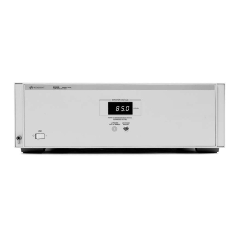
Keysight 85039B LO/IF
Distribution Unit
User's and
Service Guide
Use this manual with the Keysight Antenna
Selection Guide, part number 5968-6759E.

Notices
© Keysight Technologies,
Inc. 2008-2016
No part of this manual may be
reproduced in any form or by any
means (including electronic storage
and retrieval or translation into a
foreign language) without prior
agreement and written consent from
Keysight Technologies, Inc. as
governed by United States and
international copyright laws.
Trademark Acknowledgments
Manual Part Number
85309-90082
Edition
Edition 2, August 2016
Printed in USA/Malaysia
Published by:
Keysight Technologies
1400 Fountaingrove Parkway
Santa Rosa, CA 95403
Warranty
THE MATERIAL CONTAINED IN THIS
DOCUMENT IS PROVIDED “AS IS,”
AND IS SUBJECT TO BEING
CHANGED, WITHOUT NOTICE, IN
FUTURE EDITIONS. FURTHER, TO
THE MAXIMUM EXTENT PERMITTED
BY APPLICABLE LAW, KEYSIGHT
DISCLAIMS ALL WARRANTIES,
EITHER EXPRESS OR IMPLIED WITH
REGARD TO THIS MANUAL AND
ANY INFORMATION CONTAINED
HEREIN, INCLUDING BUT NOT
LIMITED TO THE IMPLIED
WARRANTIES OF
MERCHANTABILITY AND FITNESS
FOR A PARTICULAR PURPOSE.
KEYSIGHT SHALL NOT BE LIABLE
FOR ERRORS OR FOR INCIDENTAL
OR CONSEQUENTIAL DAMAGES IN
CONNECTION WITH THE
FURNISHING, USE, OR
PERFORMANCE OF THIS
DOCUMENT OR ANY INFORMATION
CONTAINED HEREIN. SHOULD
KEYSIGHT AND THE USER HAVE A
SEPARATE WRITTEN AGREEMENT
WITH WARRANTY TERMS
COVERING THE MATERIAL IN THIS
DOCUMENT THAT CONFLICT WITH
THESE TERMS, THE WARRANTY
TERMS IN THE SEPARATE
AGREEMENT WILL CONTROL.
Technology Licenses
The hardware and/or software
described in this document are
furnished under a license and may be
used or copied only in accordance
with the terms of such license.
U.S. Government Rights
The Software is “commercial
computer software,” as defined
by Federal Acquisition Regulation
(“FAR”) 2.101. Pursuant to FAR
12.212 and 27.405-3 and
Department of Defense FAR
Supplement (“DFARS”) 227.7202,
the U.S. government acquires
commercial computer software
under the same terms by which
the software is customarily
provided to the public.
Accordingly, Keysight provides
the Software to U.S. government
customers under its standard
commercial license, which is
embodied in its End User License
Agreement (EULA), a copy of
which can be found at
http://www.keysight.com/find/sweula
The license set forth in the EULA
represents the exclusive authority
by which the U.S. government
may use, modify, distribute, or
disclose the Software. The EULA
and the license set forth therein,
does not require or permit,
among other things, that
Keysight: (1) Furnish technical
information related to
commercial computer software
or commercial computer
software documentation that is
not customarily provided to the
public; or (2) Relinquish to, or
otherwise provide, the
government rights in excess of
these rights customarily provided
to the public to use, modify,
reproduce, release, perform,
display, or disclose commercial
computer software or
commercial computer software
documentation. No additional
government requirements
beyond those set forth in the
EULA shall apply, except to the
extent that those terms, rights, or
licenses are explicitly required
from all providers of commercial
computer software pursuant to
the FAR and the DFARS and are
set forth specifically in writing
elsewhere in the EULA. Keysight
shall be under no obligation to
update, revise or otherwise
modify the Software. With
respect to any technical data as
defined by FAR 2.101, pursuant
to FAR 12.211 and 27.404.2 and
DFARS 227.7102, the U.S.
government acquires no greater
than Limited Rights as defined in
FAR 27.401 or DFAR 227.7103-5
(c), as applicable in any technical
data.
Safety Notices
A CAUTION notice denotes a hazard. It
calls attention to an operating
procedure, practice, or the like that,
if not correctly performed or adhered
to, could result in damage to the
product or loss of important data. Do
not proceed beyond a CAUTION
notice until the indicated conditions
are fully understood and met.
A WARNING notice denotes a hazard.
It calls attention to an operating
procedure, practice, or the like that,
if not correctly performed or adhered
to, could result in personal injury or
death. Do not proceed beyond a
WARNING notice until the indicated
conditions are fully understood and
met.

Keysight 85309B User’s and Service Guide -iii
Printing Copies of Documentation from the Web
To print copies of documentation from the Web, download the PDF file from
the Keysight web site:
—Go to http://www.keysight.com.
— Enter the product model number (Ex: 85309B) in the Search function.
—Click Search.
— Click the Manuals hyperlink.
— Click the hyperlink title for the document you want to print - this downloads
the PDF
— Print the document after the PDF has fully downloaded.
Definitions
— Specifications describe the performance of parameters covered by the
product warranty (temperature –0 to 50 °C, unless otherwise noted.)
— Typical describes additional product performance information that is not
covered by the product warranty. It is performance beyond specification
that 80% of the units exhibit with a 95% confidence level over the
temperature range 20 to 30 °C. Typical performance does not include
measurement uncertainty.
— Nominal values indicate expected performance or describe product
performance that is useful in the application of the product, but is not
covered by the product warranty.
— Characteristic Performance describes performance parameter that the
product is expected to meet before it leaves the factory, but is not verified in
the field and is not covered by the product warranty. A characteristic
includes the same guard bands as a specification.
85309B Overview
The 85309B LO/IF Distribution Unit is a broadband, distributed frequency
converter that utilizes fundamental mixing to provide the performance for
antenna test systems. The 85309B, together with mixers in the antenna test
configuration (not supplied), down convert a microwave signal to an IF signal.
This IF signal is input directly to the PNA digitizer (via either front panel
jumpers or a rear panel connector), bypassing the PNA’s RF conversion stage,
for increased measurement sensitivity.
The 85309B LO/IF Distribution Unit contains LO signal amplifiers, which
amplify LO drive power through RF cables to the mixers in the antenna test
configuration. The high output power allows the mixers to be located more

-iv Keysight 85309B User’s and Service Guide
-
than seven meters from the 85309B. There are also IF amplifiers located in the
85309B, which serve as a preamplifier for the receiver, reducing the overall
system noise figure significantly.
The 85309B LO/IF Distribution Unit can be installed in a variety of
configurations for antenna testing. To learn about the various system
configurations, refer to the “Configuration Examples” section in Chapter 1 of
this document, and the online document Keysight Antenna Test Selection
Guide, part number 5968-6759E. See “Printing Copies of Documentation from
the Web” on the previous page.
85309B Options
85309B Standard
Provides one test channel and one reference channel.
85309B Option 001 - One Additional Test Channel
Adds one additional test channel. Provides a total of two test channels and one
reference channel.
85309B Option 002 - Two Additional Test Channels
Adds two additional test channels. Provides a total of three test channels and
one reference channel.
85309B Option 400 - Low and High Frequency Bands, One Test
Channel
0.1 – 1 GHz low frequency band; 0.3 – 18 GHz high frequency band. Provides a
total of one test channel and one reference channel.
85309B Option 401 - Low and High Frequency Bands, Two Test
Channels
0.1 – 1 GHz low frequency band; 0.3 – 18 GHz high frequency band. Adds one
additional test channel. Provides a total of two test channels and one reference
channel.
85309B Option 402 - Low and High Frequency Bands, Three Test
Channels
0.1 – 1 GHz low frequency band; 0.3 – 18 GHz high frequency band. Adds two
additional test channels. Provides a total of three test channels and one
reference channel.
Option 1CM - Rack Mount Kit Without Handles
Rack mount kit without handles. To obtain this item after receiving the 85309B,
order part number 5063-9214.

Keysight 85309B User’s and Service Guide -v
Option 1CP - Rack Mount Kit With Handles
Rack mount kit with handles. To obtain this item after receiving the 85309B,
order part number 5063-9221.

-vi Keysight 85309B User’s and Service Guide
-

Contents
Keysight N5241A/42A/49A Service Guide 1
Table of Contents
1. Getting Started
STEP 1. Check the Shipment. . . . . . . . . . . . . . . . . . . . . . . . . . . . . . . . . . . . . . . . . . . . . . . . . 2-1
STEP 2. Meet Electrical and Environmental Requirements . . . . . . . . . . . . . . . . . . . . . . . . . 2-1
Step 3. Connect the 85309B with Other System Components. . . . . . . . . . . . . . . . . . . . . . . 2-2
Compatible Network Analyzers . . . . . . . . . . . . . . . . . . . . . . . . . . . . . . . . . . . . . . . . . . . . 2-2
Configuration Examples . . . . . . . . . . . . . . . . . . . . . . . . . . . . . . . . . . . . . . . . . . . . . . . . . . 2-3
Step 4. (Option 40x Only): Set the 85309B Band Selection . . . . . . . . . . . . . . . . . . . . . . . . . 2-6
Step 5: Power On the 85309B . . . . . . . . . . . . . . . . . . . . . . . . . . . . . . . . . . . . . . . . . . . . . . . . 2-6
Step 6. Adjust the LO Power . . . . . . . . . . . . . . . . . . . . . . . . . . . . . . . . . . . . . . . . . . . . . . . . . 2-7
Procedure . . . . . . . . . . . . . . . . . . . . . . . . . . . . . . . . . . . . . . . . . . . . . . . . . . . . . . . . . . . . . 2-7
STEP 7. (Optional) Run the 85309B Operator’s Check . . . . . . . . . . . . . . . . . . . . . . . . . . . . 2-8
Getting Help with Your 85309B . . . . . . . . . . . . . . . . . . . . . . . . . . . . . . . . . . . . . . . . . . . . . . . 2-9
Keysight Antenna Test Selection Guide. . . . . . . . . . . . . . . . . . . . . . . . . . . . . . . . . . . . . . 2-9
Contacting Keysight . . . . . . . . . . . . . . . . . . . . . . . . . . . . . . . . . . . . . . . . . . . . . . . . . . . . . 2-9
Shipping Your Instrument to Keysight for Service or Repair. . . . . . . . . . . . . . . . . . . . . . 2-9
2. Operating Information
Electrostatic Discharge Protection. . . . . . . . . . . . . . . . . . . . . . . . . . . . . . . . . . . . . . . . . . . . . 3-1
85309B Front Panel Features. . . . . . . . . . . . . . . . . . . . . . . . . . . . . . . . . . . . . . . . . . . . . . . . . 3-3
DETECTOR VOLTAGE Display. . . . . . . . . . . . . . . . . . . . . . . . . . . . . . . . . . . . . . . . . . . . . . 3-3
LO POWER ADJUST. . . . . . . . . . . . . . . . . . . . . . . . . . . . . . . . . . . . . . . . . . . . . . . . . . . . . 3-3
LO POWER OUT OF RANGE. . . . . . . . . . . . . . . . . . . . . . . . . . . . . . . . . . . . . . . . . . . . . . . 3-4
BAND SELECTION (Option 40x Only). . . . . . . . . . . . . . . . . . . . . . . . . . . . . . . . . . . . . . . . 3-4
85309B Rear Panel Features . . . . . . . . . . . . . . . . . . . . . . . . . . . . . . . . . . . . . . . . . . . . . . . . . 3-6
Ref Mixer Connector Group . . . . . . . . . . . . . . . . . . . . . . . . . . . . . . . . . . . . . . . . . . . . . . . 3-6
Test Mixers Connector Group . . . . . . . . . . . . . . . . . . . . . . . . . . . . . . . . . . . . . . . . . . . . . 3-7
LO Source Connector Group . . . . . . . . . . . . . . . . . . . . . . . . . . . . . . . . . . . . . . . . . . . . . . 3-7
Receiver Connector Group. . . . . . . . . . . . . . . . . . . . . . . . . . . . . . . . . . . . . . . . . . . . . . . . 3-8
Available Fuses. . . . . . . . . . . . . . . . . . . . . . . . . . . . . . . . . . . . . . . . . . . . . . . . . . . . . . . . . 3-9
85309B Block Diagrams. . . . . . . . . . . . . . . . . . . . . . . . . . . . . . . . . . . . . . . . . . . . . . . . . . . . 3-10
Instrument Block Diagrams Sheet 1 . . . . . . . . . . . . . . . . . . . . . . . . . . . . . . . . . . . . . . . 3-11
Instrument Block Diagrams Sheet 2 . . . . . . . . . . . . . . . . . . . . . . . . . . . . . . . . . . . . . . . 3-11
Cable Length Limits . . . . . . . . . . . . . . . . . . . . . . . . . . . . . . . . . . . . . . . . . . . . . . . . . . . . . . . 3-13
Performing the Operator’s Check. . . . . . . . . . . . . . . . . . . . . . . . . . . . . . . . . . . . . . . . . . . . . 3-16
Function . . . . . . . . . . . . . . . . . . . . . . . . . . . . . . . . . . . . . . . . . . . . . . . . . . . . . . . . . . . . . 3-16
Description . . . . . . . . . . . . . . . . . . . . . . . . . . . . . . . . . . . . . . . . . . . . . . . . . . . . . . . . . . . 3-16
Equipment Required. . . . . . . . . . . . . . . . . . . . . . . . . . . . . . . . . . . . . . . . . . . . . . . . . . . . 3-17
LO Power Output Test . . . . . . . . . . . . . . . . . . . . . . . . . . . . . . . . . . . . . . . . . . . . . . . . . . 3-17

2 Keysight N5241A/42A/49A Service Guide
Contents
Reference IF and Test IF . . . . . . . . . . . . . . . . . . . . . . . . . . . . . . . . . . . . . . . . . . . . . . . . . 3-22
IF the Operator’s Check Fails . . . . . . . . . . . . . . . . . . . . . . . . . . . . . . . . . . . . . . . . . . . . . 3-25
3. General Information
General Specifications. . . . . . . . . . . . . . . . . . . . . . . . . . . . . . . . . . . . . . . . . . . . . . . . . . . . . . . 1-1
85309B Characteristic Performance . . . . . . . . . . . . . . . . . . . . . . . . . . . . . . . . . . . . . . . . . . . . 1-3
General Safety Considerations . . . . . . . . . . . . . . . . . . . . . . . . . . . . . . . . . . . . . . . . . . . . . . . . 1-5
Introduction . . . . . . . . . . . . . . . . . . . . . . . . . . . . . . . . . . . . . . . . . . . . . . . . . . . . . . . . . . . . 1-5
Cleaning the Instrument . . . . . . . . . . . . . . . . . . . . . . . . . . . . . . . . . . . . . . . . . . . . . . . . . . 1-5
Connector Care and Cleaning. . . . . . . . . . . . . . . . . . . . . . . . . . . . . . . . . . . . . . . . . . . . . . 1-5
Declaration of Conformity . . . . . . . . . . . . . . . . . . . . . . . . . . . . . . . . . . . . . . . . . . . . . . . . . 1-5
Statement of Compliance . . . . . . . . . . . . . . . . . . . . . . . . . . . . . . . . . . . . . . . . . . . . . . . . . 1-6
General Safety Considerations . . . . . . . . . . . . . . . . . . . . . . . . . . . . . . . . . . . . . . . . . . . . . 1-6
Regulatory Information . . . . . . . . . . . . . . . . . . . . . . . . . . . . . . . . . . . . . . . . . . . . . . . . . . . . . . 1-9
Instrument Markings . . . . . . . . . . . . . . . . . . . . . . . . . . . . . . . . . . . . . . . . . . . . . . . . . . . . . 1-9
4. Service
Replaceable Parts . . . . . . . . . . . . . . . . . . . . . . . . . . . . . . . . . . . . . . . . . . . . . . . . . . . . . . . . . . 2-1
Introduction . . . . . . . . . . . . . . . . . . . . . . . . . . . . . . . . . . . . . . . . . . . . . . . . . . . . . . . . . . . . 2-1
Ordering Information . . . . . . . . . . . . . . . . . . . . . . . . . . . . . . . . . . . . . . . . . . . . . . . . . . . . . 2-1
Replaceable Parts Listings . . . . . . . . . . . . . . . . . . . . . . . . . . . . . . . . . . . . . . . . . . . . . . . . 2-2

1
Keysight 85309B
LO/IF Distribution Unit
User’s and Service Guide
1 Getting Started
STEP 1. Check the Shipment
1. Unpack the contents of the shipping container. Keep the packaging
material in case the analyzer needs to be returned to the factory.
2. Carefully inspect the 85309B to make sure that it was not damaged during
shipment. If damaged, refer to “Contacting Keysight” on page 9.
3. Use the Contents List in the shipping container to verify the completeness
of your shipment. If not complete, refer to “Contacting Keysight” on
page 9.
STEP 2. Meet Electrical and Environmental Requirements
1. Ensure the available AC power source meets the requirements found in
“General Specifications” on page 1.
2. Ensure the operating environment meets the requirements found in
“General Specifications” on page 1.
3. Verify that the AC power cable is not damaged, and that the power-source
outlet provides a protective earth contact.
4. Plug the unit into an appropriate AC power source.
This instrument has autoranging line voltage input. Be sure the supply
voltage is within the specified range.
Always use the three-prong AC power cord supplied with this product.
Failure to ensure adequate earth grounding by not using this cord may
cause personal injury or product damage.

1-2 Keysight 85309B User’s and Service Guide
Getting Started
Step 3. Connect the 85309B with Other System Components
1-
Step 3. Connect the 85309B with Other System Components
Your antenna test system configuration includes the 85309B and a PNA
network analyzer. The need for other components is determined by the type of
measurements required.
To learn about the various system configurations, refer to the Keysight Antenna
Test Selection Guide, part number 5968-6759E. See “Printing Copies of
Documentation from the Web” in the first section of this manual.
Compatible Network Analyzers
The following network analyzers are compatible with the 85309B.
The 85309B should be turned off when connecting it with other system
components.
Family Receiver Firmware Required Options
PNA E836xC All revisions H11
N522xA All revisions 020
PNA-X N524xA All revisions 020
N5264A All revisions None

Keysight 85309B User’s and Service Guide 1-3
Getting Started
Step 3. Connect the 85309B with Other System Components
Configuration Examples
Figure 1-1 Simplified Configuration Block Diagram

1-4 Keysight 85309B User’s and Service Guide
Getting Started
Step 3. Connect the 85309B with Other System Components
1-
Figure 1-2 Typical Far-Field Configuration

Keysight 85309B User’s and Service Guide 1-5
Getting Started
Step 3. Connect the 85309B with Other System Components
Figure 1-3 Typical PNA-X Compact Range Configuration

1-6 Keysight 85309B User’s and Service Guide
Getting Started
Step 4. (Option 40x Only): Set the 85309B Band Selection
1-
Step 4. (Option 40x Only): Set the 85309B Band Selection
The Band Selection knob on the front panel of the 85309B Option 400/401/402
models allows the user to switch between the low band, high band, and
external selections. For more information, refer to “85309B Front Panel
Features” on page 3.
Step 5: Power On the 85309B
Power on the 85309B by pressing the front panel On/Off switch.
If the 85309B will not power on, make sure the instrument is plugged into an
operating AC power outlet, and check the fuse.

Keysight 85309B User’s and Service Guide 1-7
Getting Started
Step 6. Adjust the LO Power
Step 6. Adjust the LO Power
The procedure below is applicable to all 85309B models, and assumes the user
has basic knowledge on the antenna test system. To learn about the various
antenna test systems, refer to the Keysight Antenna Test Selection Guide, part
number 5968-6759E. See “Printing Copies of Documentation from the Web” in
the first section of this manual.
The front panel of the 85309B has a DETECTOR VOLTAGE window, an LO
POWER ADJUST mechanism, and an LO POWER OUT OF RANGE LED. Refer to
“85309B Front Panel Features” on page 3. The value shown in the DETECTOR
VOLTAGE window is the voltage coming from a power detector in the reference
mixer. The voltage is directly proportional to the amount of LO power arriving
at the mixer. A label on the reference mixer shows the precise voltage which
corresponds to the power at the mixer's LO input. In the procedure below, you
adjust the LO POWER ADJUST so the DETECTOR VOLTAGE display matches
the voltage on the mixer label.
Once set, the ALC loop will maintain the desired LO power level regardless of
LO frequency. Repeat the procedure below only if you change one of the mixer
modules or the LO source.
Find the detector voltage value written on the reference mixer. Record the
value in Table 1-1 below.
Procedure
1. Set the LO source power to 6 dBm.
2. Observe the voltage displayed in the 85309B’s front panel DETECTOR
VOLTAGE window.
3. Adjust the 85309B’s LO POWER ADJUST mechanism until the voltage
displayed in the window is equal to the voltage written in Table 1-1 (also
shown on the reference mixer label). If the LO POWER OUT OF RANGE LED
is lit, there is an unleveled ALC state. To fix the problem, refer to “LO
POWER OUT OF RANGE” on page 4. Note that due to the long LO cable
length (the RF cable between the LO source and the 85309B) you must
compensate for cable loss by increasing the LO source power.
Table 1-1 Value Indicated on the Reference Mixer
Parameter Value
mV (typically –40 to –80):
The voltage displayed in the DETECTOR VOLTAGE window varies with
frequency. This is normal. The LO POWER OUT OF RANGE LED is lit only if
the system's automatic leveling loop cannot level the voltage sufficiently.
This can happen if the LO source is disconnected, or if more power is
needed than the 85309B unit can supply for a given frequency range.

1-8 Keysight 85309B User’s and Service Guide
Getting Started
STEP 7. (Optional) Run the 85309B Operator’s Check
1-
STEP 7. (Optional) Run the 85309B Operator’s Check
The operator’s check should be performed when you first receive your 85309B,
and any time you wish to have confidence that it is working properly. The
operator’s check does not verify performance to specifications, but should give
you a high degree of confidence that the 85309B is performing properly.
For instructions, refer to “Performing the Operator’s Check” on page 16.

Keysight 85309B User’s and Service Guide 1-9
Getting Started
Getting Help with Your 85309B
Getting Help with Your 85309B
Keysight Antenna Test Selection Guide
Use the Keysight Antenna Test Selection Guide (part number 5968-6759E) to:
— Learn about interface requirements between system components.
— Understand issues related to selecting the equipment required to make
antenna measurements.
For information on how to view and print this document online, see “Printing
Copies of Documentation from the Web” in the first section of this manual.
Contacting Keysight
Assistance with test and measurements needs and information or finding a
local Keysight office are available on the Web at:
http://www.keysight.com/find/assist
If you do not have access to the Internet, please contact your Keysight field
engineer.
Shipping Your Instrument to Keysight for Service or Repair
If you wish to send your instrument to Keysight Technologies for service or
repair:
— Include a complete description of the service requested or of the failure and
a description of any failed test and any error message.
— Ship the instrument using the original or comparable anti-static packaging
materials.
— Contact Keysight for instructions on where to ship your instrument.
In any correspondence or telephone conversation, refer to the Keysight
product by its model number and full serial number. With this information,
the Keysight representative can determine whether your product is still
within its warranty period.

1-10 Keysight 85309B User’s and Service Guide
Getting Started
Getting Help with Your 85309B
1-

1
Keysight 85309B
LO/IF Distribution Unit
User’s and Service Guide
2 Operating Information
Electrostatic Discharge Protection
Protection against electrostatic discharge (ESD) is essential while removing
assemblies from or connecting cables to the 85309B. Static electricity can
build up on your body and can easily damage sensitive internal circuit
elements when discharged. Static discharges too small to be felt can cause
permanent damage. To prevent damage to the instrument:
—always have a grounded, conductive table mat in front of your test
equipment.
—always wear a grounded wrist strap, connected to a grounded conductive
table mat, having a 1 MΩ resistor in series with it, when handling
components and assemblies or when making connections.
—always wear a heel strap when working in an area with a conductive floor. If
you are uncertain about the conductivity of your floor, wear a heel strap.
—always ground yourself before you clean, inspect, or make a connection to
a static-sensitive device or test port. You can, for example, grasp the
grounded outer shell of the test port or cable connector briefly.
—always ground the center conductor of a test cable before making a
connection to any static-sensitive device. This can be done as follows:
1. Connect a short (from your calibration kit) to one end of the cable to
short the center conductor to the outer conductor.
2. While wearing a grounded wrist strap, grasp the outer shell of the
cable connector.
3. Connect the other end of the cable to the test port and remove the
short from the cable.
Figure 2-1 shows a typical ESD protection setup using a grounded mat and
wrist strap. Refer to Chapter 6 for part numbers.

2-2 Keysight 85309B User’s and Service Guide
Operating Information
Electrostatic Discharge Protection
2-
Figure 2-1 ESD Protection Setup
This manual suits for next models
1
Table of contents
Other Keysight Technologies Power Distribution Unit manuals
