Keystone RV SolarFlex 600i-L Operating and maintenance manual

REV 1.6 fsi-solutions.com

REV 1.6 fsi-solutions.com

1
Dear SolarFlex Owner,
Congratulations and thank you for your purchase of your new Keystone SolarFlex 600i-L System. We know this
will help you on your journey with your new RV.
To help get you started, we encourage you to take a few minutes and review the Owner’s Manual thoroughly.
There are many components, system settings and equipment unique to a recreational vehicle. Getting an
understanding of how they function will be important to safe operation, getting the most from your system, and
your overall enjoyment.
If you have any questions, please contact your selling dealer or the Keystone Customer Service Group at
866-425-4369. Additional information and resources about your system can be found at www.keystonerv.com or
www.fsi-solutions.com/owners-manuals.
The Future Solutions Team thanks you again for purchasing a Keystone product. Enjoy camping with your own
power!
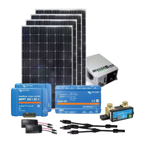
(2) 30A Solar Roof Ports
(600W) Future Solutions Solar Array
50A Victron Smart MPPT Controller
Battery Guardian System
(With Low Voltage Disconnect)
(270Ahrs) Dragonfly®
Lithium Ion Battery
Victron Cerbo GX
Victron 3kW Inverter (with
Built-in Transfer Switch)
(2) CS2 Solar Cable Splitters
Victron SmartShunt Battery Monitor
This manual is based on the latest information available at the time of publication. Due to continuous product development and improvements,
Future Soltuions reserves the right to make changes in product specifications and components without prior notice. The most recent version of
the owner’s manual can be found on our website at www.fsi-solutions.com/owners-manuals or www.keystonerv.com under the Customer
Service heading.
- The Future Soltutions Team
REV 1.6 fsi-solutions.com

2
REV 1.6 fsi-solutions.com
Victron Products
Your system includes components from Victron’s
“Smart” energy line with Bluetooth connectivity in
place of a physical remote display. This includes the SmartShunt, MPPT SmartSolar Controllers, and
the Cerbo GX. Your MultiPlus Inverter does not have Bluetooth capabilities. The SmartShunt is
monitoring your battery state and tracking how much power is flowing to or from the battery bank,
giving you valuable information regarding your State-of-Charge (SOC).
The MPPT SmartSolar Controller is regulating the power produced by the solar panels to charge the
batteries. Both of these devices have stand-alone Bluetooth connectivity and can be viewed individ-
ually by using the VictronConnect App on a smart phone or tablet. These devices also report to the
Cerbo GX, which acts as a connectivity and monitoring hub for your system. This section contains
details for each of these devices.
Opening the VictronConnect app will cause it to look
for ANY Victron items with a Bluetooth signal within
range. Specific items can be identified by the Icon, as
well as the device “nick-name”. The default nickname
is the device serial number. Serial numbers
for your devices, as well as information needed to
connect to your Cerbo GX are found on the sticker
located on the cover of your component plate, as
well as on the side of your battery.
The first time you connect to any device, you will have to enter the default password (000000). You
can change the password when prompted if you choose, or you can also change the password in
settings at a later time.
If you have lost or forgotten your password, they can be reset through the app, but
this does require a PUK number (a special code) that is on the serial number
sticker of the device. This number is required to ensure that you have
physical possession of the device before clearing a password.
Each of your Bluetooth devices will have three tabs across the
top: Status, History, and Trends.
Shows live-time information regarding battery
conditions.
The device stores historical values in non-volatile
memory. This means this data will not be lost when the power to the device has been interrupted.
These can be used at a later date to evaluate usage patterns and battery health.
This section of VictronConnect enables data-logging, but only while the app is connected and
communicating with the SmartShunt. It will simultaneously log two of the following parameters:
Voltage, Current, Power consumed Ah, or State of Charge.
Once connected, you can change the device nick name, and change or add a password. To do this,
click the settings ( ) in the top right corner. Once in main settings menu, select the menu ( ) in the top
right corner, and choose “Product Info”. This is where you can change the name of the device, check
for updated firmware, and change the password to log onto the device.

3
REV 1.6 fsi-solutions.com
Victron Products
Default pincode is 000000.
After connecting, the pincode can be changed
by going into “Settings” ( ), select “Menu” ( ),
“Product Info”, and here you can change the
product name and pincode.
You will need to “forget” the device from your device list. If you are not sure how to do this, a link will be
displayed on your phone or tablet during the process that you can follow to learn how.
Locate and write down the PUK number from the device you are trying to reset.
On the SmartShunt and SmartSolar Controller: this is on a sticker on the side of the component.
Reference below for label locations.
Select the Menu ( ) to the right of the signal strength meter.
Choose “Reset PIN code”.
If you have not removed the device from your Bluetooth list yet, follow the link at the bottom of the
warning message, complete the removal, and start at step 1 again. Otherwise, proceed to step 5.
Enter PUK number and click “OK”.

4
REV 1.6 fsi-solutions.com
This system is utilizing the SmartSolar MPPT 100|50
Solar Controller. A Solar Controller charges a lower
nominal-voltage battery from a higher nominal
voltage PV array. The Solar Controller will charge the
battery with a current up to its rated output. The
SmartSolar MPPT 100|50 Solar Controller has a
maximum of 50 amps output. Selecting the SmartSolar Controller in
VictronConnect will open the main screen.
This shows how many watts are being
processed through this SmartSolar Controller.
This shows the voltage of your panels
and how much current is coming from the panel array.
This shows the battery bank
voltage, charging current and the current charging state of the
SmartSolar Controller.
Victron Products
Blinking
On
Off
NOTE *1) The bulk LED will blink briefly every 3 seconds when the system is powered but
this is insufficient power to start charging.
NOTE *2) The LED(s) might blink every 4 seconds indicating that the Charger is receiving
data from another device, this can be:
A GX Device (e.g. Color Control with a Multi in ESS mode)
A VE.Smart network link via Bluetooth (with other MPPT Chargers and/or a BMV or
Smart Battery Sense)
NOTE *3) e.g. Calibration and/or settings data lost, current sensor issue.
In the settings menu ( ), under the “Battery settings” section, you have
the option to reduce the max charge current, disable the Charger, or
change the battery type. It is recommended that the battery type be set
to “rotary switch” and it should read “Position 7” in the info box.
The charging state of the Controller can also be observed using the LED
lights on the physical Solar Controller.
NOTE: Battery type settings on VictronConnect App
over-rides the rotary switch settings of charge Controller.

5
REV 1.6 fsi-solutions.com
The SmartShunt is a very valuable piece of equipment in your system. This
is the component that is responsible for helping you keep track of just how
much energy is left in your battery bank at any given time. This component
simply measures battery voltage and current. With those measurements,
and the info provided to it through the settings menu, SOC (State-of-Charge),
and Time Remaining are calculated.
Percentage of energy in battery bank. This is
a calculated number based on settings and should be periodically
checked against the Voltage to SOC chart. See At Rest Voltage vs
SOC Chart on pg 22.
This is the battery bank voltage level.
A negative number indicates current (A) flowing from the
battery bank; a positive number indicates current (A) flowing to the
battery bank.
This is the NET Power (Watts) flowing to or from the battery
bank. A negative number indicates power (W) flowing from; a positive
number indicates power (W) flowing to the battery bank.
The SmartShunt keeps track of the Amp-hours
removed from the battery (compensated for the efficiency).
Example: If a 10-amp load is ran for 4 hours, the read out will show
-40.0 Ah (-10amps x 4 hour = -40.0).
This is an estimate of how long the battery
bank can support the present load under the present conditions.
If the loads being ran fluctuate heavily, it is best not to rely on this
reading too much as it is a momentary readout and should be
used as a guideline only.
Victron Products
*NOTE: If “– – –” are shown, this means that the shunt is in an
unsynchronized state. This can occur when the system has been
left unpowered for a period of time and is powered up again.
See paragraph 5.3 “Synchronizing the SmartShunt” in the
SmartShunt Manual.
NOTE: is the NET current flow (adding all charging sources and subtracting all loads)
flowing to or from the battery bank.

6
REV 1.6 fsi-solutions.com
Victron Products
The settings on the SmartShunt need to be accurate in order to
provide proper data regarding the Consumed Amp-hours, State of
Charge, and Time Remaining readouts. If you find your readings
are off, review your settings to ensure they are correct. All settings
are recommended by Dragonfly Energy.
This should be set to the size of your battery bank.
600i-L with GC3 Batteries should be set to 270Ah
600i-L with GC2 Batteries should be set to 300Ah
This is the battery voltage that MUST be met
before the SOC is reset to 100%.
DFE Recommended Setting – 14.1 V
This setting is used in the “time to go” calculation.
DFE Recommended Setting – 0%
This setting is used to determine when SOC is reset
to 100%.
DFE Recommended Setting – 3.50%
This setting is the amount of time that
“Charged Voltage” and “Tail Current” must be met before the SOC
is reset.
DFE Recommended Setting – 3m
This setting is used in calculations of SOC.
DFE Recommended Setting – 1.05
This setting compensates for the amp-hours lost to heat during charging.
DFE Recommended Setting – 99%
This setting controls the smallest value of current that the system will recognize.
DFE Recommended Setting – 0.10A
This is the time period that is averaged to get the “Time-to-go” value.
DFE Recommended Setting – 3m
This selection will cause the SOC to reset to 100% anytime the Shunt is
powered up after having been disconnected.
DFE Recommended Setting – Disabled
With this setting, you can manually set the state of charge value. This setting is only
active after the SmartShunt has, at least once, been synchronized (automatically or manually). For
more information on this, see At Rest Voltage vs SOC Chart in the appendix on pg 22.
DFE Recommended Setting – N/A
This option can be used to manually synchronize the SmartShunt.
DFE Recommended Setting – N/A
This option can be used to calibrate the zero reading if the battery monitor
reads a non-zero current even when there is no load, and the battery is not being charged.
DFE Recommended Setting – N/A

7
REV 1.6 fsi-solutions.com
Precision Circuit Products
The Battery Guardian Auto installed in your system acts as a smart battery disconnect switch.
The DC loads inside of your coach are running through this component. When the switch is
turned on, the BGA is monitoring the battery voltage. If your battery bank voltage reaches
11.5 VDC for 2 minutes, the BGA will turn off, disconnecting all interior loads from DC power.
When the BGA senses the battery is being charged, it will automatically turn back on. You can manually
disconnect the DC loads inside of the coach by turning off the BGA switch.
Auto-Disconnect Voltage: < 11.5VDC for 2 min.
Auto-Reconnect Voltage:
When BGA senses battery is being charged.
Coach Disconnect
(if located outside coach)
Your batteries are equipped with built in battery heaters to ensure
cold climate does not stop your batteries from charging. The heaters
are enabled or disabled by a lighted switch inside of the coach or on the
iN-Command Display Commander’s Battery Heat Trigger. When
the switch is turned on, the heaters will automatically activate when the
internal temperature of the battery drops below approximately 35°F
(1.6°C) and will automatically shut off when the internal temperature
exceeds approximately 45°F (7.2°C).
The heaters draw 1.8 amps (per battery) of power and typically run on a 30% duty cycle. This means
at 0°F, the heaters will be on 30% of the time, and off 70% of the time. That means if it is cold, we can
expect 0.6 Ah of energy (per battery) to be used to keep the batteries at proper charging temperatures.
If you are using the coach and the temperature is below freezing, you will want to turn on the battery
heat to ensure you are able to take advantage of charging from your solar set up. The heat can either
be turned on just prior to charging, or left on while the coach is in use. Both options have pro’s and
con’s and are based on personal preference and use case.
While leaving the heat on while the coach is in use, you could be using energy to keep the batteries
warm when it is not necessary (remember: it is only really necessary when trying to charge) it also
ensures that if you are charging from solar, the batteries are always able to accept power when it is
available.
Only enabling the heat prior to charging will conserve more battery power, but it can also take an
extended period of time for the batteries to warm up to be able to charge if they are cold soaked. In the
end, the important thing to remember is if the temperature is at or below 35°F, you will need to activate
the battery heat in order to charge the batteries.
Batteries
NOTE: If the battery has been cold soaked (exposed to below freezing
temperatures for a long period of time without the heater enabled), it
will take 2-4 hours for the internal components of the battery to heat
up enough for the battery to accept a charge.
NOTE: DRAGONFLY DOES NOT RECOMMEND BATTERY HEATER BE ACTIVE WHEN STORING THE BATTERY.

8
REV 1.6 fsi-solutions.com
Victron Products
The 600i-L is equipped with a Victron MultiPlus 3kVA Inverter. The MultiPlus
is a powerful true sine wave Inverter and sophisticated battery charger all
in one package. When on shore or generator power, the MultiPlus will pass
power through to the loads from the source. Any available power that is not
used for the loads will be dedicated to battery charging.
The MultiPlus comes from the factory programmed for charging the Lithium
battery bank that is on the system. If the need arises to change the
programming, you MUST reach out to a trained professional.
On the 600i-L, the Inverter is running a specific set of AC circuits. The main
panel provides power to the Inverter when on shore or generator power
and the Inverter passes that power through to a sub-panel. The sub-panel
powers a circuit of general outlets as well as one of the air conditioners. When shore or generator
power is not present, the Inverter will draw power from the battery bank and alter it from DC to AC
power to run the items on the sub-panel.
The Inverter is set up in Unlimited Power Supply (UPS) mode. This means that when the unit is
plugged in to shore or a generator, if the breaker trips or a power outage occurs, the Inverter will
automatically take over and keep the inverted circuits from shutting down.
The Inverter only monitors the loads that are powered through the sub panel. This means, when
plugged in to a smaller shore outlet (or running a portable generator), you can still run more loads
than the power source can supply. If this happens, the breaker will trip and only the inverted loads
on the sub-panel will remain powered. Some suggestions can be found in the Tech Tips section for
using a small shore outlet or portable generator.
The Inverter can be monitored and controlled through the Cerbo using the Remote Console. This is
discussed in more detail in the Remote Console section of this manual starting on pg 12.
The Inverter has a rocker switch on the cover that can limit the functionality to “Charger Only” or
“Off”. When the rocker switch is in the “On” position, the state of the Inverter can be changed
through the Remote Console.
NOTE: Setting the rocker switch to “Charger Only” or “Off”
over-rides the settings in the Remote Console.

9
Connecting automatically via the QR code:
Locate the QR code sticker on the component plate of your system.
Scan the QR code using your phone’s camera function or a QR code
scanning app.
If supported by your phone, this will prompt you to connect to
the Wi-Fi access point.
Once connected, open VictronConnect.
Select the GX device from the list then open the Remote Console.
Manually Connecting:
Stand as close as possible to the Cerbo GX (within a few meters).
Go to the Wi-Fi settings on your phone or tablet.
After searching for local networks, the Cerbo GX will show up in the
list as something like “Venus-HQ1940DEFR4-3b6”.
Connect to Wi-Fi using the Wi-Fi key printed on the sticker on your
component plate.
Open VictronConnect, it will start auto-
matically scanning the Wi-Fi network.
Once found, select the GX device from
the list.
Open the Remote Console. Read more about this on pg 12.
Victron Products
This all-new communication center allows you to always have control over your
system from wherever you are. All of your Victron equipment is reporting to the
Cerbo GX which then displays the data on an intuitive interface that is easy to
understand and operate. The Cerbo GX has built in Bluetooth, built in Wi-Fi
access point, as well as the ability to connect to a local LAN or Wi-Fi Network.
The Bluetooth option on the Cerbo GX has limited functionality. It is intended to
be used to assist with initial connection and networking configuration. Review
the section for VictronConnect (pg 2) for instructions on how to connect a device
with Bluetooth. Once opened, you will be able to set the PIN, name your device,
and select external Wi-Fi networks.
If you have a Wi-Fi signal you would like to use to access the Cerbo GX (possibly through a hot-spot or
other mobile network) you can log the Cerbo GX onto the network through the Bluetooth connection.
From the main screen, select the Settings ( ).
Choose your desired network from the list of
available networks.
Enter your network password.
If you do not have a Wi-Fi signal, you can still access the remote console by accessing the internal Wi-Fi
access point of the Cerbo GX.
NOTE: This Wi-Fi access point does not have an
internet connection and is only used to view the
remote console when you are near the unit. You
can access this network in two ways.
REV 1.6 fsi-solutions.com

10
Go to http://www.victronenergy.com, click on the ‘Login’ tab and select ‘VRM’. Select
the ‘Register for Free’ icon below the log in screen. Here, you will need to provide your
name, email address, phone number, city, country, and select a new password.
You should receive a verification email with a link to your new account. Next
time you go to the VRM homepage, you will simply have
to enter your email and your password. Clicking on the
link takes you to a page to
add your installation.
Click ‘Cerbo GX’.
It will ask for an Installation ID and an Installation name. The Installation ID can be found on the
serial number sticker of your 600i-L system. This should be located on the cover of the plate. It can
also be found on a sticker on the bottom of the Cerbo GX. The VRM ID
can also be found using the Remote Console. For more on that, see
Remote Console section starting on pg 12.
Enter the alpha-numeric code for the VRM Portal ID and you can
choose to name the installation anything you want (example: Jones RV).
Once your Cerbo is linked to your new VRM account, you will see an
overview of your system as the main backdrop, with a menu of options
on the left.
Victron Products
NOTE: CERBO GX NEEDS TO BE POWERED UP AND BE
LINKED TO A WI-FI NETWORK WITH INTERNET ACCESS.
Opens the data tracking portion of the portal. Under
‘widgets’ in the top right corner, you can find all of the different
options of data available for each of your devices.
This opens a screen that shows each of your connected
components. Clicking on a component shows you the serial number,
firmware version, and much more.
Options here include adding other users to the account,
changing the name of the installation, and unlinking an installation.
This allows you to access the menu for your Cerbo
from any computer. To use this, the Cerbo must be linked to the
internet and the two-way communication option must be enabled.
Allows you to save notes for long term information.
Allows you to upload photos.
¡ Enables others to openly view your harvest information.
¢ Shows any alarms that have occurred with a time stamp.
£ Enables you to have data emailed to you.
REV 1.6 fsi-solutions.com

11
Shows the amount of power from the available source (shore or generator) that is being used
by the Charger and the loads on the sub-panel.
Shows the state the Inverter is currently in. Bulk, Absorb, and Float indicate charging.
Inverting indicates no shore or generator power is present and the Inverter is supplying power to the
sub-panel.
Shows the amount of power consumed by loads on the sub-panel. (NOT ALL AC LOADS.)
Shows SOC%, Battery Bank Voltage, Current Flow, and Time to go calculations.
This is a calculated value that shows how much of your power is consumed by DC loads.
Any power consumed or presented to the system, not from a Victron component, is included in this
calculation.
This shows the total power all monitored Solar Controllers are producing. If solar is
expanded, the new Controller must be plugged in to the Cerbo with a VE.Direct cable for this to be
accurate.
Victron Products
REV 1.6 fsi-solutions.com

12
REV 1.6 fsi-solutions.com
DEVICE LIST SCREEN
Opening the Remote Console will bring up the system overview
screen. This shows your battery information and total combined
solar power. On the home screen there is also a moving graphic
that represents where the power is coming from and going to in
your system. The Cerbo GX has a lot of functionality that goes
beyond the scope of this manual. For purposes of this manual, we will cover the basic items that a user
needs to know to be able to utilize the off grid system. If you are interested in more detailed infor-
mation about the capabilities of the Cerbo, please see the User Manual for the Cerbo GX (link on pg 23).
By selecting the space bar, the selection bar will momentarily pop up at the bottom of the screen.
This is used to toggle between the Menu, and the home screen. Selecting “Pages” will return you to this
home screen.
Selecting Menu will open to the main menu where you can select between the individual components
hooked up to a Cerbo GX or you can go into settings of the Cerbo GX itself. Selecting any one of the
components will allow you to view more detailed information about what that component is doing.
Below the components is a 'Notifications' tab
that will open a screen that will show the report
of any error logged by the system. At the bottom
of the list is the Settings tab.
Opening the Settings Menu will bring up a
vast selection of functions (shown to the
right). Many of these options are used with
various other configurations of Victron
Equipment. Not all apply to the SolarFlex
system. Only items that pertain to the
SolarFlex system will be discussed.
For more information on any of the settings,
please refer to the Cerbo GX Owners Manual
(link on pg 23).
Victron Products
Go BackEscape
Space Bar
Left Arrow Right Arrow
Up Arrow
Down Arrow
OVERVIEW SCREEN

13
REV 1.6 fsi-solutions.com
Victron Products
Allows for you to choose who can access
your system.
This option opens a support tunnel
between secure servers at Victron and your Cerbo GX.
This is not used and should remain off.
¤ This will reboot your Cerbo GX in the event of
certain settings changing or a communication glitch.
Enable or disable an audible alarm when
a fault occurs.
This should remain off.
This is the firmware version the Cerbo
GX is currently running.
¥ This code allows Victron Engineers to
trace firmware.
Options to update firmware if internet is
available.
¥ Option to upload firmware
downloaded to a USB drive or SD cardfrom a PC.
Stores previous version of
firmware.
¥ This is the date and time in Coordinated
Universal Time.
¥: This displays local time. You can also
adjust the time and date manually here.
This allows you to choose a time zone to set
the local date and time by.

14
REV 1.6 fsi-solutions.com
Victron Products
This allows connection to the
Remote Console from the VRM or VictronConnect without
an additional password.
Allows an additional password
to be entered before remote console can be activated.
Allows remote console to be opened
through the VRM portal.
¦ Indicates if the Remote
Console is currently connected through the VRM portal.
Enables a device to open the Remote
Console if it is on the same network as the Cerbo GX.
Enable or disable data logging.
Device identifier for VRM.
How often data is logged.
Only allow connection
through secure channels.
Time since last communication between
VRM and Cerbo GX.
Report of any communication error
between VRM and Cerbo GX.
Allows for data to be sent
to the Cerbo from the VRM for Remote Console and other
features.
If there is an error
connecting to Wi-Fi, enabling this will automatically cause the
Cerbo GX to re-boot in an attempt to clear the error.
This allows the Cerbo GX to enable
the internal Wi-Fi option to provide a means of linking a
smartphone or tablet if no other network is available.
This will allow you to connect to any
available Wi-Fi network.

15
REV 1.6 fsi-solutions.com
Victron Products
Selecting the SmartShunt will allow you to view some of the
more detailed information not seen on the home screen.
Each SmartSolar Controller will have its own item line in the main menu screen. By selecting one of the
Controllers, the details screen will open to show valuable information regarding that specific Solar
Controller.
NOTE: All settings must be changed through the
Bluetooth connection for the SmartShunt. The Cerbo
GX will only display information from this device. For
more information on settings for the SmartShunt,
see pg 6.
NOTE: All settings must be changed through the Bluetooth connection for the SmartSolar
Controllers. The Cerbo GX will only display information from this device. See pg 4 for
more information SmartSolar Controller settings.
Enable or disable Bluetooth communication
from the Cerbo GX.
Change the pincode needed to connect to the
Cerbo GX via Bluetooth.
¡)
This shows if the Controller is on or off, and what
charge stage it is in.
This shows the voltage and current that the solar
panels are providing to this Controller.
This shows the battery voltage as read at the
output terminals of the Solar Controller and charging
current the Controller is producing.
Total amount of watts the system has
produced with one Charger.
Total amount of watts the system has
produced overall.
This is not used on this system.

16
REV 1.6 fsi-solutions.com
Victron Products
Selecting the MultiPlus from the menu opens the details page where infor-
mation regarding the Inverter can be found. You can scroll through the list
by pressing the down arrow. The only settings that can be changed from
the Remote Console are the input current limit, and switch state. These
settings are identified with a black triangle in the lower left corner of the
line item. To change one of these settings, use the down arrow to select
the desired setting, press the center space bar to open the edit screen, change to the desired value,
and press the green arrow at the bottom of the page.
This allows you to change the Inverter mode from the Remote Console.
Normal usage will only call for the use of ON or OFF.
On– This will allow the Inverter to automatically toggle between inverting and charging depending
on the availability of shore power.
Inverter Only– This will allow the Inverter to be on when shore power is NOT available, but will turn
the unit off if shore power is available. The Charger will not turn on when shore power is available.
Charger Only– This will allow the Charger to turn on if shore power is available, but will turn the unit
off if shore power is NOT available. The Inverter will not turn on when shore power is not available.
Off– This will turn off both the Inverter and Charger regardless of what power is available.
This shows what the present state of the Inverter is.
This sets the threshold at which the
Inverter will try not to allow the coach to exceed when using
shore power or a generator. As the draw from shore power
approaches the limit set here, the Inverter will take steps in
an attempt to reduce the draw to remain under the limit. It
will first reduce the power used for charging and if the draw is still too high.
This is the battery voltage measured at the Inverters DC terminals.
This is the current the Inverter is removing from, or adding to the
battery bank. A negative number here means the Inverter is drawing power from
the battery bank.
SOC of battery bank.
Default values as there is no
temperature sensor installed.
This indicates if shore power is present
at the Inverter.
This is the voltage and current that the Inverter
is seeing from shore power. If you are not plugged in, this
will be blank.
This is how much the AC loads are requiring through the Inverter.
If on shore power, this is the amount of power passed through the Inverter. If
you are not plugged in this is the amount of power the Inverter is producing to
support the loads.

17
REV 1.6 fsi-solutions.com
Why do I see tank sensors on my settings menu?
This is a default setting in the Cerbo GX and can be deactivated. Deactivating the
tank sensor inputs will remove the unused items from the menu list. To do this:
Open the Remote Console.
Enter Menu and select “Settings”.
Use down arrow to scroll down to I/O (bottom of settings list).
Enter I/O and select Analog Inputs.
Turn off all inputs in list.
Use left arrow to back out to Main Settings Menu.
¡ Use up arrow to scroll to General (at the top of the settings list).
¢ Enter General and select “Reboot”.
How are DC loads measured?
This reading is actually a calculation done by the Cerbo, so it is possible for the accuracy to stray. The Cerbo uses
information from the connected Victron equipment to determine where power is going. Any power that is not
consumed or presented by a piece of Victron equipment that is connected to the Cerbo is accredited to DC loads.
What should my shore power limit be set to for my Inverter?
A good rule of thumb is to ALWAYS set the input current rating to match the breaker size on your shore outlet or
portable generator.
My unit was connected to Wi-Fi but now I am showing a communication error?
Sometimes, communication can be lost when changing between mobile towers. Most often this is corrected by
simply re-booting the Cerbo.
I can not access the remote portal from the VRM
This can happen when your system first connects to the internet after being offline for a period of time. This is
because the system is unloading the logged data to the VRM. When observing the VRM portal from a computer,
you should notice the “last connected” time getting smaller until it reaches “real-time”. At this point you should be
able to open the remote console.
If your system has not been offline, or if you are still having issues, follow these steps to verify settings and reboot
the Cerbo.
Ensure you are connected to a Wi-Fi network with an internet connection.
Open the menu, select “Settings”, then select “Remote Console”.
Select “Disable Password”.
Ensure “Enable on VRM” is selected (slider should be blue).
Back out of Remote Console, select “VRM Portal”.
Ensure Logging is Enabled.
Ensure last contact is less than the log interval.
Ensure Connection error shows ‘NO ERROR’.
Ensure VRM two-way communication is enabled.
Back out of Remote Console, select general, select “Reboot Device”.
I can not access the remote portal from my smartphone or tablet.
In order to access the remote portal from a smartphone or tablet, you must either have your smartphone or
tablet on the same Wi-Fi network as the Cerbo GX, or have the Cerbo GX connected to the VRM through an
internet connection. See “Connecting to the Cerbo” section of manual (pg 9).
Frequently Asked Questions

18
REV 1.6 fsi-solutions.com
Frequently Asked Questions
When and how should I update the firmware?
The Solar Controllers, battery monitor, and Cerbo GX all have Firmware that can be updated.
For SmartSolar Controllers and SmartShunt:
Open the VictronConnect app on a smartphone or tablet and connect to the device.
Select the Settings ( ) in the top right corner.
Select the Menu ( ) in the top right corner and open Product Info. If new firmware is available, you will be able
to select ‘Update’ to download and install. This will need to be done for each Solar Controller and the SmartShunt
separately.
For the Cerbo GX:
Open Remote Console.
Enter Menu, select Firmware.
Select Online Updates.
Select “Press to check for update” and follow prompts.
For the MultiPlus Inverter:
It is not required to keep your Inverter updated to the latest firmware version. Stable systems should be left with
their current firmware. Firmware updates should only be done when it is recommended to fix an issue you are
experiencing or add a new feature that is required by the installation.
Can I change the name shown for my component?
Changing the name of the individual components is easiest through the Remote Console. To accomplish this:
Open the Remote Console.
Open the Menu, select the device.
At the bottom of the details menu for each device is an option named ‘Device’.
Select this option, and here you can change the name displayed for your device.
Enter new name and select the green check mark at the bottom of the screen.
Why don’t I have power to my DC loads? (BGA)
Most often, this is caused when the BGA is off or when the BGA goes in to low voltage protection
mode. If switch is on, BGA is in low voltage protection mode. This happens when your battery
voltage has dropped to 11.5 volts for 2 minutes. This means the batteries need to be recharged.
The options to do so are:
Leave things off and let solar charge the battery bank.
Plug in to shore power or a portable generator and let the Inverter/Charger charge the battery bank.
In either case, when the BGA senses that the batteries are charging it will reconnect the loads.
My DC loads shut down, but my battery monitor says I have plenty of SOC left.
Settings may need adjusted on your battery monitor. DFE recommended setting values are found on pg 6. You
can also verify the SOC of the battery bank by using the At Rest Voltage vs SOC Chart on pg 22.
What should my Input Current Limit be set to for my Inverter?
Typically, this can be left to 30 amps on the 600i-L. Reducing the Input Current Limit on this system will only
reduce the Chargers output if the loads begin to approach the limit. This is discussed more in the question,
“How do I use a smaller shore plug or portable generator?” on the next page.
NOTE: After updating firmware, all settings will be reset to their factory defaults. The unit will be in
stand-alone mode and all programmed battery charging parameters will be reset.
Other manuals for SolarFlex 600i-L
1
Table of contents
Other Keystone RV Inverter manuals
Popular Inverter manuals by other brands

Platinum
Platinum 7000 R3 Installation and user guide

TBEA
TBEA TC500K3US-O installation manual

Selectronic Australia
Selectronic Australia LD450-12 operating manual

enphase
enphase IQ 7 Quick install guide

CyberPower
CyberPower CPSPI3700EVF380 user manual

Avlite
Avlite AV-SIGN-20 Installation & service manual

Tracon
Tracon INV230ACB user manual

VOLTCRAFT
VOLTCRAFT MSW 300 operating instructions

Cobra
Cobra ROAD WARRIOR operating instructions

Mitsubishi Electric
Mitsubishi Electric FR-F800 Sample Screen Manual

Generac Portable Products
Generac Portable Products 1654-0 owner's manual

SEW-Eurodrive
SEW-Eurodrive MOVIDRIVE modular Compact operating instructions