Keywish Panther-Tank-4.0 User manual

2
Revised Version Of History
Date
Version
Description
Author
2019/8/14
V.1.0
Create
Carl.Du
2019/8/27
V1.1
Update the picture
Abbott.Chen

3
CONTENTS
Chapter 1 PREFACE .........................................................................................................................................5
1.1 Purpose..........................................................................................................................................5
1.2 Product Introduction .....................................................................................................................5
Chapter 2 Preparation ........................................................................................................................................6
2.1 On BLE UNO R3 Master Control Board and Extension Board..........................................................6
2.1.1 BLE UNO R3 Master Control Board.....................................................................................6
2.1.2 MotorDriverBoard Expansion board interface diagram ...........................................................7
2.2 Development environment Arduino IDE.............................................................................................8
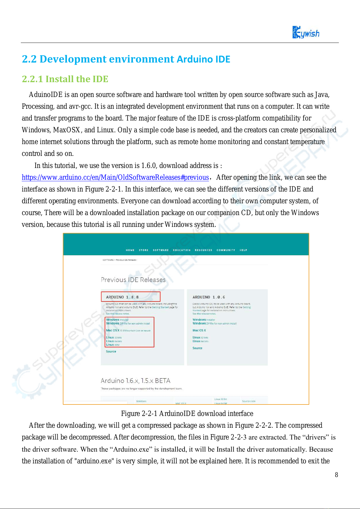
2.2.1 Install the IDE...........................................................................................................................8
2.2.2 Install Driver...........................................................................................................................10
2.2.3 IDE Interface Introduction......................................................................................................14
Chapter 3 Installation.......................................................................................................................................17
3.1 Tank Assembly ..................................................................................................................................17
3.1.1 Lower metal backplane copper column and battery installation ............................................17
3.1.2 load-bearing wheels、pedrail and motor installation.............................................................19
3.1.3 Servo and UNO board installation..........................................................................................24
3.1.4 Upper acrylic floor mounting..................................................................................................29
Chapter 4 Experiment......................................................................................................................................31
4.1 Servo ..................................................................................................................................................31
4.1.1 Servo Introduction ..................................................................................................................31
4.1.2 Working principle...................................................................................................................32
4.1.3 steering test test.......................................................................................................................33
4.2 RGB WS2812B Experiment..............................................................................................................34
4.2.1 RGB WS2812B Description...................................................................................................34
4.2.2 RGB WS281B working principle...........................................................................................34
4.2.3 WS281B drive principle .........................................................................................................35
4.2.4 RGB WS281B Test Program..................................................................................................36
4.3 Passive Buzzer ...................................................................................................................................36
3.2.2.1 Description...........................................................................................................................36
4.3.2 Buzzer working principle........................................................................................................37
4.3.3 Alarm Test ..............................................................................................................................37
4.4 Motor test procedure..........................................................................................................................43
4.4.1 Motor control principle...........................................................................................................43

4
4.4.2 Motor Test Procedure .............................................................................................................44
4.5 Infrared Remote Control....................................................................................................................46
4.5.1 Introduction.............................................................................................................................46
4.5.2 Working Principle...................................................................................................................47
4.5.3 Acquiring Infrared remote value.............................................................................................47
4.6 Ultrasonic obstacle avoidance............................................................................................................49
4.6.1 Introduction to Ultrasound......................................................................................................49
4.6.2 Module parameter...................................................................................................................49
4.6.3trasonic principle......................................................................................................................50
4.6.4 Experimental procedure..........................................................................................................52
4.7 PS2 Wireless Control (optional)........................................................................................................52
4.7.1 Introduction to the kit..............................................................................................................52
4.7.2 Experimental steps..................................................................................................................54
4.7.3 Software Design......................................................................................................................55
4.8 CC2540 Bluetooth Module Test Experiment ....................................................................................57
4.8.1 Introduction to Bluetooth Module ..........................................................................................57
4.8.2 TI CC2540 Bluetooth Module Parameters ...........................................................................57
4.8.3 Bluetooth module test experiment steps.................................................................................58
4.9 ESP-M2 Wifi Module Test Experiment (Optional)...........................................................................62
4.9.1 Introduction to Wifi Module...................................................................................................62
4.9.2 Wifi Module Features .............................................................................................................62
4.9.3 Wifi Module Test Experiment Steps.......................................................................................63

5
Chapter 1 PREFACE
1.1 Purpose
Our purpose is to offer a learning platform for DIY lovers, makers and beginners, help to get a better
understanding of Arduino, and its expansion system design methods and principles, as well as the
corresponding hardware debugging methods. Further deepen the understanding of the design and application
of Arduino and its extended system.
The instruction manual mainly introduces the installation, hardware and software for Panther- Tank
from the easy to the difficult and complicated. There are two parts for the instruction manual.
The first part mainly introduces how to use the common developing software and the method of
downloading,debugging. And the second part mainly introduces about hardware and software. For the
hardware part, it mainly introduces the functions, principles of every module, and for the software part, there
are many examples for customers, it mainly introduces the applications of the Tank.
There are lots of detailed schematic diagrams and example codes for each module, which is strictly
tested to ensure the accuracy and precision. Moreover, you can easily find the library files in the
corresponding file folder and download through the UART/simulator to the BLE uno board for the
corresponding functions . You can debug each module according to the course or directly assemble the car
to enjoy the fun of a maker.
1.2 Product Introduction
"Tank" is ATMEGA328P-PU as the main control chip, and TB6612FGN is used as a multi-functional
crawler car for motor drive chip. Compared with the traditional car, "Tank" is also equipped with wireless
control (Bluetooth, infrared remote control). It can automatically avoid obstacles. Of course, Maker can also
add or subtract other functions through its own Idea, such as adding automatic tracking, PS2 gamepad,
adding wifi control, robotic arm, etc.
"Tank" is equipped with all kinds of materials, technical manuals, routines, etc., and teaches you from
entry to proficiency. Every electronic enthusiast can easily get started and realize the functions they want.
Product features
High power all metal geared motor
Integral stamping molding kit,easier Installation,tighter
2400mAH,7.4v ,rechargeable li-battery,longer battery life,and more dynamic
2 RGB turn lights
Buzzer Turn around reminder

6
Infrared remote control
Android App control
Chapter 2 Preparation
2.1 On BLE UNO R3 Master Control Board and Extension Board
2.1.1BLE UNO R3 Master Control Board
In " Hummer-Bot ", we used the BLE-UNO R3 as the main control board, which has 14 digital input/output
pins (6 of which can be used as PWM output), 6 analog inputs, and a 16 MHz ceramic resonator, 1 USB
connection, 1 power socket, 1 ICSP head and 1 reset button. It contains everything that supports the
microcontroller; You just need to connect it to a computer via a USB cable or start with an AC-DC adapter
or battery.
`Figure 2.1.1 Arduino BLE - UNO R3 Board
Technical specifications:
Working voltage: 5 V
BLE chip : TI CC2540
BLE work channel :2.4G
Bluetooth transmission distance: 50m open distance
Interface : Micro-USB
Input voltage: USB powered or external 7V~12V DC input

7
Output voltage: 5V DC output and 3.3V DC output and external power input
Microprocessor: ATmega328 (Chip data sheet is in the documentation)
Bootloader:Arduino Uno
Clock frequency: 16 MHz
Support USB interface protocol and power supply (without external power supply)
Support ISP download function
Digital I/O port: 14 (4 PWM output ports)
Analog input port: 6
DC Current I/O Port: 40mA
DC Current 3.3V Port: 50mA
Flash memory: 32 KB (ATmega328) (0.5 KB for bootloader)
SRAM :2 KB (ATmega328)
EEPROM:1 KB (ATmega328)
Size:75x55x15mm
2.1.2 MotorDriverBoard Expansion board interface diagram
Figure 2.1.2 Expansion Board Interface Diagram

8
2.2 Development environment Arduino IDE
2.2.1 Install the IDE
AduinoIDE is an open source software and hardware tool written by open source software such as Java,
Processing, and avr-gcc. It is an integrated development environment that runs on a computer. It can write
and transfer programs to the board. The major feature of the IDE is cross-platform compatibility for
Windows, MaxOSX, and Linux. Only a simple code base is needed, and the creators can create personalized
home internet solutions through the platform, such as remote home monitoring and constant temperature
control and so on.
In this tutorial, we use the version is 1.6.0, download address is :
https://www.arduino.cc/en/Main/OldSoftwareReleases#previous,After opening the link, we can see the
interface as shown in Figure 2-2-1. In this interface, we can see the different versions of the IDE and
different operating environments. Everyone can download according to their own computer system, of
course, There will be a downloaded installation package on our companion CD, but only the Windows
version, because this tutorial is all running under Windows system.
Figure 2-2-1 ArduinoIDE download interface
After the downloading, we will get a compressed package as shown in Figure 2-2-2. The compressed
package will be decompressed. After decompression, the files in Figure 2-2-
the installation of "arduino.exe" is very simple, it will not be explained here. It is recommended to exit the

9
anti-virus software during the installation process, otherwise it may affect the installation of the IDE. After
the installation is complete, click "arduino.exe" again to enter the IDE programming interface.
Figure 2-2-2 Arduino IDE Installation Package
Figure 2-2-3 Extracted files
When finish the installation of the IDE,connect to the Arduino motherboard,click“My Computer”
“Properties”“Device Manager”“Viewing Ports (COM and LTP)” , If you can see as the Figure
2-2-4
Figure 2-2-4 Driver installation success interface

10
that indicates the driver has been installed successfully,At this time we open the IDE, select the
corresponding development board model and port in the toolbar to use normally. If you see Figure 2-2-5, it
means that the computer does not recognize the development board and you need to install the driver
yourself.
Figure 2-2-5 Driver is not successfully installed interface
Notice:
1)If you connect the controller board to the computer, the computer does not respond. Right-click "My
Computer" and select Open Device Manager then find viewing port (com & lpt). If there is no com or lpt, or
only an unknown device, there is a problem with the controller board or the USB cable.
2)Right-click "My Computer" and select Device Manager, find the viewing ports (COM and LPT). If there
is a yellow Arduino UNO exclamation point, this means you need to install the driver yourself.
3)If you install the driver again and again, it eventually fails. Please uninstall the driver and re-install>
install the driver automatically> restart the computer.
2.2.2 Install Driver
If your computer is a Windows 7 system

11
1)Right-click on "My Computer" and open the Device Manager, find viewing the ports (COM and LPT). At
this point you will see a "USB Serial Port", right-click "USB Serial Port" and select the "Update Driver
Software" option.
Figure 2-2-6 Updated Driver Interface
2)Next, select the "Browse my computer for driver software" option.
Figure 2-2-7 Driver Update Selection Screen

12
3)Driver path: " BLE-UNO _Driver \ ccxxxx_usb_cdc.inf" click "next", as shown in figure 2-2-8
Figure 2-2-8 Driver file selection interface
4)If you have already installed, the following figure will automatically inform you that the driver was
successful.

13
Figure 2-2-9 Driver Installation Successful Interface
At this time, we return to the "Device Manager" interface, the computer has successfully identified Arduino,
as shown in the below Figure 2-2-10 .then open the Arduino compilation environment, you can open the
Arduino trip.
Figure 2-2-10 Driver Success Recognition Interface

14
Notice In Win10 system, some Arduino are connected to the computer (non-genuine chips are difficult to
identify), the system will automatically download the corresponding driver, so you can not install the driver
yourself, but in the Win7 system, you have to do it yourself.
In addition, we can see that the USB serial port is identified as COM15 in the above figure, but it may
be different with different computer, you may be COM4, COM5, etc., but USB-SERIAL CH340, this must
be the same. If you do not find the USB serial port, you may have installed it incorrectly or the system is
incompatible.
2、If your computer is a Windows 8 system: Before installing the driver, you should save the files you are
editing because there will be several shutdowns during the operation.
1)Press "Windows key" + "R"
2)Iput shutdown.exe / r / o / f / t 00
3)Click the "OK" button
4)The system will reboot to the "Select an option" screen
5)Select "Troubleshooting" from the "Select an option" screen
6)Select "Advanced Options" from the "Troubleshoot" screen
7)
8)Click the "Restart" button
9)
10)Select "Disable Driver Signature Enforcement"
11)Once the system is booted, you can install Arduino driver the same as Windows7
3、If your computer is a Windows XP system: The installation steps are basically the same as for Windows 7,
please refer to the above Windows 7 installation steps.
2.2.3 IDE Interface Introduction
Nextly,we introduce the Arduino IDE interface, firstly enter the software directory. Then you can see the
arduino.exe file and double-click to open the IDE. As shown in Figure 2-2-11.
Figure 2-2-11 Software Catalog
1、The first thing you can see is the interface of the following figure. The functions of the toolbar
buttons are "Compile" - "Upload" - "New Program" - "Open Program" - "Save Program" - "Serial Monitor" ,
as shown in Figure 2-2-12.

15
Figure 2-2-12 Arduino IDE Interface
2.There are 5 menus on the menu bar, but we mainly introduce File and Tools. Click File, the interface as
shown in Figure 2-2-13 will be displayed, you can see the Examples and Preference options. The Examples
are some of the Arduino's own programs, these are compiled without errors, the normal use of the program,
a great help for beginners. The Preference option, parameter settings, such as language,
fonts and so on.
Figure 2-2-13 File Menu Bar Options
3、Click Tools, the interface shown in Figure 2-2-14 will pop up. Here we can see two options: Board and
Port. In the board option, we can see the commonly used Arduino development board model, we only need
to choose according to their own development board. In the Port option, the USB serial port is mainly
selected, as shown in Figure 2-2-15. If you are not sure, you can check it in the "Device Manager" and select
the corresponding COM port.

16
Figure 2-2-14 Tools interface
Figure 2-2-15 USB serial port selection
So far, we have basically completed all the work. The next step is actual experiments. Open any program in
Examples. First compile the program. If it is compiled correctly, it can be directly downloaded to the
development board and the corresponding device of the connection number. With wires, you can see the
corresponding phenomenon.

17
Chapter 3 Installation
3.1 Tank Assembly
Firstly, we open the box, take out all the components and put it on the table lightly. (Note: There are
many devices, be careful when installing to prevent some devices from being lost)
3.1.1 Lower metal backplane copper column and battery installation
Step 1: The installation of the copper plate under the metal bottom plate
Figure 3-1-1 Schematic diagram of copper column installation on lower metal bottom plate
Figure 3-1-2 Under metal floor copper column installation effect diagram

18
Step 2:Battery installation
Note: Attach a piece of Velcro to the back of the battery and attach another to the top of the metal base plate.
Figure 3-1-3 Battery box installation diagram
Figure 3-1-4 Battery box installation effect diagram
Step 3:Welding DC head
Connect the power cable: Firstly, find the matching two power cables (the same as the wires used by the
motor, one red and one black) and connect the two cables to the DC power head. The DC power connector is
shown in Figure3-1-5The rubber ring marked as "1" can be removed to open the shell and then welding the
wires to the +12V and GND, as shown in Fig.3-1-6
Figure 3-1-5 Power DC Head

19
Figure 3-1-6 Schematic diagram of wire welding
3.1.2 load-bearing wheels、pedrail and motor installation
Step 1:Installation of load-bearing wheels
Figure 3-1-7 load-bearing wheels installation checklist

20
Figure 3-1-8 Schematic diagram of load-bearing wheels installation
Note: The load-bearing wheels must be reserved for 1mm from the inner nut.
Figure 3-1-9 Effect diagram of load-bearing wheels installation
Step 2: Install the motor
Figure 3-1-10 Schematic diagram of motor installation
This manual suits for next models
2
Table of contents
Other Keywish Toy manuals
Popular Toy manuals by other brands

VTech Baby
VTech Baby My Friend Fawn instruction manual

Horizon Hobby
Horizon Hobby Blade Infusion 180 instruction manual

Carrera RC
Carrera RC 370301016 Assembly and operating instructions

Victory Tailgate
Victory Tailgate Kubb instruction manual

Gro Company
Gro Company grohush operating instructions

TILLIG BAHN
TILLIG BAHN 501468 quick start guide

Amewi
Amewi 26069 instruction manual

Dynaflite
Dynaflite Bird of Time instruction manual

Radica Games
Radica Games 74005 Lighted Blackjack instruction manual

Activision
Activision Wii SkylanDers SWAP Force Instruction booklet

HOMCOM
HOMCOM 390-003V01 Assembly instruction

Odyssey
Odyssey Hovering Soccer Ball Set instruction manual