KIAM Sherwood 52 User manual

Kiam
Power Products
Kiam Sherwood Multi-Tool
Petrol Strimmer, Brush Cutter, Hedge Trimmer, Pruner
Instructions Manual
Read instructions manual before use!
Equipmart Ltd
Kiam House
Birchill Road
Knowsley Ind. Park North
Merseyside
L33 7TD
United Kingdom
T: 0044 151 548 5500
F: 0044 151 548 5599
© Equipmart Ltd
www.kiamproducts.co.uk
Kiam
Power Products

SAFETY FIRST
WARNINGS IN THE MANUAL
WARNING
IMPORTANT
NOTE
1
Contents
Instructions will contain warnings within this manual, they will be marked with a symbol concern-
ing critical points which must be taken into consideration to prevent any possible serious bodily
injury. You are requested to read all such instructions carefully and follow them without fail.
This mark indicates instructions which must be followed in order to prevent accidents that could lead to serious
bodily injury or death.
This mark indicates instructions which must be followed to prevent any mechanical failures, breakdowns and/or
damage.
This mark indicates hints or directions that are useful in the use of this machine.
1.
2.
3.
4.
5.
6.
7.
8.
9.
10.
11.
12.
13.
14.
Specification .............................................................................
Parts Location ...........................................................................
Warning labels on the machine ................................................
Symbols on the machine ..........................................................
For safe operation .....................................................................
Setup ........................................................................................
Fuel ...........................................................................................
Operation ..................................................................................
Maintenance .............................................................................
Storage .....................................................................................
Disposal ....................................................................................
Troubleshoot Guide ..................................................................
Spare parts ...............................................................................
Warranty ...................................................................................
2
3
3
3
4
8
11
12
16
19
19
20
20
21

1. Specification
2
Engine
Description 5in1 Petrol Multifunction Garden Tool
Model / Type Sherwood 52
Accessories
1 Adjustable carrying strap with shoulder pad
1 Mixing tank (600ml)
1 Tool Kit
Engine model TT1E44F-5
Engine type 2-Stroke - vertical single cylinder
Bore x Stroke 44 x 34.6mm
Displacement 52cm³
Engine speed (Idle / Max) 3000 min-¹ / 7800 min-¹
Compression ratio 7:1
Fuel / oil ratio 40:1
Fuel tank capacity 1200cm³
Ignition CDI system
Spark plug L7T or equivalent
Starting method Recoil (manual)
Cooling system Forced air
Sound pressure level (LPA)102dB(A) K=3dB(A)
Sound power level (LWA) 111dB(A) K=3dB(A)
Vibration level max. (idling /running) 5.11m/s² / 9.66m/s² (K=1.5m/s²)
Dry weight (approx.) 5.2kg
Blade rotation direction Counterclockwise (from operator’s view)
Cutting device Metal blade (3 teeth) Nylon thread spool
Cutting device dimensions 255 x 25.4 x 1.6mm 2 threads - 2.5m x 2.4mm
Cutting diameter 255mm 410mm
Max rotation speed (max engine speed) 7100 min-¹ 6600 min-¹
Dry weight with attachment 6.9kg (approx.) 6.2kg (approx.)
Brush cutter and strimmer
Chain and Guide Bar 10” (250mm)
Cutting length 250mm
Oil tank 150cm³
Dry weight with attachment 8.4kg (approx.)
Chain: Teeth: 44 / Gauge: 0.050” / Pitch 3/8” / no load speed 15m/s
Pole Pruner Hedge trimmer
Blade holder 390mm
Blade spacing 19mm
Max cutting diameter ≤ 5mm
Working angle adjustment From 90° to 270°
Dry weight with attachment 8.9kg (approx.)

2. Parts location
3
22. Chain cover
21. Saw chain
20. Guide bar
18. Blade
17. Cutting line head
16. Angle transmisson
15. Cutting guard
14. Air cleaner cover
13. Choke lever
12. Primer
11. Fuel tank
10. Starter knob
9. Spark arrester
3. Stop switch
8. Knob bolt
7. Shaft tube
6. Throttle set button
18
19
20
21
22
23
9
10
11
12
13
14
23
4
5
6
8
1
7
15
16
17
1. Loop handle
2. Suspension point
4. Throttle cable
5. Throttle trigger
19. Transmission
23. Transmission
3. Warning labels on the machine
15m (50ft)
(1) (2) (3) (4) (5) (6) (7)
(1) Read owner’s manual before operating this machine.
(2) Wear head, eye and ear protection.
(3) Wear foot protection.
(4) Wear gloves.
(5) Beware of thrown objects.
(6) Warning / Attention.
(7) Keep all people 15 meters away from the machine.
4. Symbols on the machine
For safe operation and maintenance, symbols are carved in relief on the machine. According to these indications,
please be careful not to make a mistake.
The opening to refuel the “PETROL MIX”
Position: FUEL TANK CAP
The direction to close the choke
Position: AIR CLEANER COVER
The direction to open the choke
Position: AIR CLEANER COVER
Screw direction to increase/decrease
chain oil flow.
Position: Bottom of the TRANSMISSION
MIN MAX
Never modify your machine. We will
not warrant the machine if you use a
modified machine or if you do not
follow the proper usage written in this
manual.

gases contain dangerous carbon
monoxide.
2. Never use the product,
a. when the ground is slippery
or when you can’t maintain a
steady posture.
b. At night, at times of heavy fog,
or at any other times when
your field of vision might be
limited and it would be diffi-
cult to gain a clear view of the
working area.
c. During rain, during storms at
times of strong or gale-force
winds, or at any other times
when weather conditions
might make it unsafe to use
the product.
WORKING PLAN
1. You should never use the prod-
uct when under the influence of
alcohol, when suffering from ex-
haustion or lack of sleep, when
suffering from drowsiness as a re-
sult of having taken cold medicine
or at any other time when a pos-
sibility exists that your judgment
might be impaired or that you
might not be able to operate the
product properly and in a safe
manner.
2. When planning your work sched-
ule, allow plenty of time to rest.
Limit the amount of time over
which the product is to be used
continuously to somewhere
around 30 ~ 40 minutes per ses-
sion, and take 10 ~ 20 minutes of
rest between work sessions. Also
try to keep the total amount of
work performed in a single day
under 2 hours or less.
WARNING
1. If you don’t observe the working
time, or working manner (See
“USING THE PRODUCT”), Re-
petitive Stress Injury (RSI) could
occur.
If you feel discomfort, redness and
swelling of your fingers or any
other part of your body, see a doc-
tor before getting worse.
2. To avoid noise complaints, in gen-
eral, operate product between
8 a.m. and 5 p.m. on weekdays
and 9 a.m. to 5 p.m. on weekends.
1.
2. Keep this manual handy so that
you may refer to it later when-
ever any questions arise. Also
note, if you have any questions
which cannot be answered
herein, contact the dealer from
whom you purchased the prod-
uct.
3. Always be sure to include this
manual when selling, lending, or
otherwise transferring the own-
ership of this product.
4. Never allow children or anyone
unable to fully understand the
directions given in the manual
to use the machine.
WORKING CONDITION
1.
(1) Helmet
(2) Ear protectors
(3) Protection goggles or face
protector
(4) Thick work gloves
(5) Non-slip-sole work boots
2. And you should carry with you.
(1) Attached tools
(2) Properly reserved fuel
(3) Spare blade
(4)Things to notify your working
area (rope, warning signs)
(5) Whistle (for collaboration or
emergency)
(6) Hatchet or saw (for removal of
obstacles)
(7) First-aid kit
3. Do not wear loose clothing, jew-
elry, short trousers, sandals, or go
barefoot. Do not wear anything
which might be caught by a mov-
ing part of the unit. Secure hair
so it is above shoulder length.
WORKING CIRCUMSTANCE
1. Never start the engine inside a
closed room or building. Exhaust
5. For safe operation
4
Read this manual carefully until
you completely understand and
follow all safety and operating
instructions. Also know how to
stop the machine quickly in the
case of an emergency.
When using the product you
should wear proper clothing and
protective equipment. (Available
at www.kiamproducts.co.uk)

5. For safe operation
BEFORE STARTING THE ENGINE
1. The area within a perimeter of
15 m of the person using the
product should be considered a
hazardous area into which no one
should enter. If necessary, yellow
warning rope, warning signs
should be placed around the pe-
rimeter of the area. When work is
to be performed simultaneously
by two or more persons, care
should also be taken to constantly
look around or otherwise check
for the presence and locations of
other people working so as to
maintain a distance between
each person sufficient to ensure
safety.
2. Check the condition of working
area to avoid any accident by hit-
ting hidden obstacles such as
stumps, stones, cans, or broken
glass.
IMPORTANT
Remove any obstacle before begin-
ning work.
3. Inspect the entire unit for loose
fasteners and fuel leakage. Make
sure that the cutting attachment
is properly installed and securely
fastened.
4. Be sure the cutting attachment
guard is firmly attached in place.
5. Always use the harness. Adjust
the strap for comfort before start-
ing the engine. The strap should
be adjusted so the left hand can
comfortably hold the handlebar
grip approximately waist high.
STARTING THE ENGINE
1. Keep bystanders and animals at
least 15 m away from the operat-
ing point. If you are approached,
immediately stop the engine.
2.
WARNING
Never place the throttle into the
high-speed position when starting
the engine.
3.
USING THE PRODUCT
IMPORTANT
Cut only materials recommended by
the manufacturer. And use only for
tasks explained in the manual.
1. Grip the handles firmly with both
hands using your whole hand.
Place your feet slightly apart
(slightly further apart than the
width of your shoulders) so that
your weight is distributed evenly
across both legs, and always be
sure to maintain a steady, even
posture while working.
2. Keep cutting attachment below
waist level.
3. Maintain the speed of the engine
at the level required to perform
cutting work, and never raise the
speed of the engine above the
level necessary.
4. If the unit starts to shake or vi-
brate, turn off the engine and
check the whole unit. Do not use
it until the trouble has been prop-
erly corrected.
5. Keep all parts of your body away
from rotating cutting attachment
and hot surfaces.
6. Never touch the muffler, spark
plug, or other metallic parts of the
engine while the engine is in op-
eration or immediately after shut-
ting down the engine. Doing so
could result in serious burns or
electrical shock.
5
The machine is equipped with a
centrifugal clutch mechanism,
so the cutting attachment will
begin to rotate as soon as the
engine is started. When starting
the engine, place it onto the
ground in a flat open area and
hold it firmly into place to ensure
neither the cutting part or throttle
come into contact with any
obstacle when the engine starts.
After starting the engine, check
to make sure that the cutting
attachment stops rotating when
the throttle is moved back fully to
its original position. if it continues
to rotate even after the throttle
has been moved back fully, turn
off the engine and call your
authorized Kiam dealer.
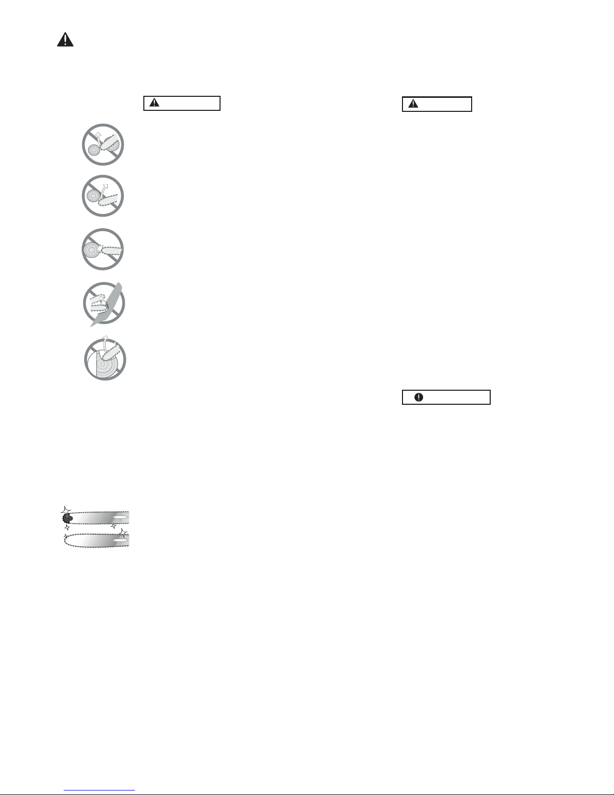
7. Never operate the pruner at an
angle greater than 60° in order to
reduce the risk of being struck by
falling objects during operation.

4.
3.
WARNING
Approaching or contacting elec-
tric power lines with pruning saw
may cause serious injury or death
from electrocution.
Electricity can jump from one
point to another by means of arc-
ing or may be conducted through
damp branches. Maintain a clear-
ance of at least 15m between Pole
saw and any electrical line carry-
ing live current.
•IF SOMEONE COMES
1. Guard against hazardous situa-
tions at all times. Warn adults to
keep pets and children away from
the area. Be careful if you are ap-
proached. Injury may result from
flying debris.
2. If someone calls out or otherwise
interrupts you while working, al-
ways be sure to turn off the en-
gine before turning around.
MAINTENANCE
1. In order to maintain your product
in proper working order, perform
the maintenance and checking
operations described in the
manual at regular intervals.
2. Always be sure to turn off the en-
gine and disconnect the spark
plug wire before performing any
maintenance or checking proce-
dures.
WARNING
The metallic parts reach high tem-
peratures immediately after stop-
ping the engine.
Under no circumstances should
you ever take apart the product
or alter it in any way. Doing so
might result in the product be-
coming damaged during opera-
tion or the product becoming un-
able to operate properly.
HANDLING FUEL
1.
2. Never smoke while operating the
unit or refilling its fuel tank.
3. When refilling the tank, always
turn off the engine and allow it to
cool down. Take a careful look
around to make sure that there are
no sparks or open flames any-
where nearby before refueling.
4. Wipe spilled fuel completely us-
ing a dry rag if any fuel spillage
occurs during refueling.
5. After refueling, screw the fuel cap
back tightly onto the fuel tank and
then carry the unit to a spot 3 m
or more away from where it was
refueled before turning on the en-
gine.
TRANSPORTATION
1. When hand-carrying the product,
cover over the cutting part if nec-
essary, lift up the product and
carry it paying attention to the
blade.
2. Never transport the product over
rough roads over long distances
by vehicle without removing all
fuel from the fuel tank. If doing so,
fuel might leak from the tank dur-
ing transport.
5. For safe operation
6
In the event that any part must
be replaced or any maintenance
or repair work not described in
this manual must be performed,
please contact your authorized
Kiam dealer.
The engine is designed to run on
mixed fuel which contains highly
flammable petrol. Never store
cans of fuel or refill the tank in
any place where there is a boiler,
stove, wood fire, welding sparks,
electrical sparks or any other
source of heat or fire which might
ignite the fuel.

ment with the engine running!
Never attempt chain adjust-
pruner.
KICKBACK SAFETY PRECAUTIONS
FOR PRUNER USERS
WARNING
•
•
(1)
(2)
(3)
(4)
(5)
(6)
WARNING
•
Make sure the chain and sprocket are
correctly adjusted before operating the
•Always make sure the cutting attach-
ment is properly installed and firmly
tightened before operation.
•Never use a cracked or warped guide
bar: replace it with a serviceable one
and make sure it fits properly.
•If a saw blade should bind fast in a
cut, shut off the engine immediately.
Push the branch or tree to ease the
bind and free the blade.
•Do not operate the pole pruner with
the muffler removed.
•
When cutting a limb that is under ten-
sion, be alert for springback so that you
will not be struck by the moving limb.
•Always stop the engine immediately
and check for damage if you strike a
foreign object or if the machine be-
comes tangled. Do not operate with
broken or damaged equipment.
IMPORTANT
•Do not make unauthorized modifica-
tions or substitutions to the guide bar
or chain.
•Never allow the engine to run at high
RPM without a load. Doing so could
damage the engine.
•Keep the pruner as clean as possible.
Keep it free of loose vegetation, mud,
etc
5. For safe operation
7
Kickback may occur when the nose
or tip of the guide bar touches an
object or when the wood closes in
and pinches the pruner in the cut.
Contact with the tip may in some
cases cause a sudden jolt kicking the
guide bar up and back towards the
operator. Pinching the chain along
the top of the guide bar may suddenly
push the guide bar back towards the
operator. Either of these reactions
may cause you to lose control of the
machine which could cause serious
personal injury.
Do not entirely rely on safety devices
built onto your machine. As a pruner
user you should take several steps to
keep cutting jobs free from accidents
or injuy.
With basic understanding of kickback
you can reduce or eliminate the
element of surprise. Sudden surprise
contributes to accidents.
Keep a good grip on the machine
with both hands, the right hand on the
throttle and the left hand on the
handle. Always use a firm grip to help
reduce kickback and maintain control
of the machine.
Make certain that the are in which you
are cutting is free from obstructions.
Do not let the nose of the guide bar
touch a log, branch or any other
obstruction which could be hit whilst
you are operating the machine.
Cut at high engine speeds.
Follow the chainsaw chain manufac-
turers for sharpening and mainte-
nance instructions.
Only use replacement bars and
chains specified by the manufacturer.

6. Setup
Insert the cable
to the end of
adjuster Full on stopper
Idling adjust screw
M3 screw
Adjuster
MOUNTING ENGINE
1.
2.
3.
IMPORTANT
Tighten the screws gradually.
CONNECTING THROTTLE WIRE
1. Remove the air filter cover.
2. Connect the end of the throttle wire to the joint on the
top of the carburetor.
3. Connect throttle wire with carburetor. Insert the cable
to the end of adjuster fix the throttle cable by tighten-
ing M3 screw. (Tightening torque: 0.4 ~ 0.8 N.m.)
4.Make sure the ‘STOPPER-PLATE’ of carburetor moves
to contact with ‘IDLING ADJUST SCREW’ and the
‘SWING-ARM’ of carburetor moves to contact with
‘FULL ON STOPPER’ by gripping throttle lever.
CONNECTING SWITCH WIRES
•Connect the switch wires between the engine and the
main unit. Pair the wires of the same colour.
SUSPENSION POINT
NOTE
Shoulder harness goes on this point
•
Mount the handle to the shaft tube and suspension point
at a location that is comfortable for you.
•
MIN
SPACING
About 19 inches (48 cm)
INSTALLING HANDLE
arrow mark
SUSPENSION POINT
8
JOINT ATTACHMENT
•Insert the attachment to the main shaft.
•Tighten the knob bolt securely .
Knob bolt
Push the shaft tube towards the clutch housing and
rotate the drive by hand to check that it is engaged
with the gears.
Insert the shaft tube into the clutch housing and align
the positioning hole on the clutch housing and the
shaft tube. Install the screw.
Fasten the clamp securely with two screws.
Install the shaft grip to the shaft tube and clamp
down at a position most suitable for you.
HARNESS
WARNING
ALWAYS WEAR THE PROVIDED HARNESS WHEN
USING THE MACHINE!
Always make sure the machine is hooked
securely to the harness. If you don’t, you will not
be able to control the machine safely. This may
result in injury to yourself and/or others. Never
use a harness with a defective quick release or
any other damage.
HOW TO WEAR HARNESS
1.
(1) Hanger
Wear the provided harness with the hanger on
your right side.

6. Setup
HARNESS QUICK RELEASE
WARNING
While holding the unit by your right hand securely, press
both sides of the buckle.
(1) Buckle
9
INSTALLING CUTTING ATTACHMENT GUARD
•
(1) Cutting attachment guard
(2) Plate
(3) Screw
INSTALLING CUTTING HEAD
1.
2.
The harness is equipped with a quick release mecha-
nism to help release the machine from the harness in
emergency situations.
Make sure to check the quick release mechanism is
working correctly BEFORE operating the machine.
Make sure to hole the machine securely when using
the quick release.
Put the cutting attachment guard on the gearbox,
attach it with 4 screws.
Lock the gear shaft into position to stop it from rotat-
ing by inserting the supplied tool into the upper
holder on the gearbox, loosen and remove the nut.
Screw in the cutting head to the gear shaft over the
holders and tighten securely.
ATTACHING THE PRUNER
(1) Main pipe
(2) Transmission
(4) Fastening bolt
(5) Bolt
1.
2.
3.
4.
5.
Remove the cap on the end of the drive shaft.
Remove the screw from the end of the transmission.
Insert the end of the gear case into the drive shaft
Line up the hole on the end of the transmission with
the hole on the drive shaft and screw in firmly.
Screw the bolt to fix the mechanism into place.
WARNING
1. Loosen the nut and remove the chain cover.
2. Mount the guide bar then fit the chain around the bar
and sprocket.
A standard package contains the items as shown below.
(1) Guide bar (2) Saw chain
(3) Transmission (4) Sprocket
(5) Chain tension adjust screw (6) Nut
(7) Chain tensioner nut (8) Chain cover
Install the guide bar and the saw chain on the transmis-
sion as follows.
The chain has very sharp edges, always use protec-
tive gloves for safety.
WARNING
Pay attention to the correct direction of the chain.
3. Fit the chain tensioner nut into the lower hole of the
guide bar, then install the chain cover, and fasten the
mounting nut to finger tightness.
(1) Hole (2) Moving direction (3) Chain tensioner nut
(3) Screw hole
BALANCING THE UNIT
1. Adjust the bands of the harness to have the blade
parallel to the ground when standing in your normal
working position to provide you with the most com-
fort whilst operating the machine

6. Setup
4.
(1) Chain tension adjusting screw
(a) Loosen (b) Tighten
5.
(1) Tighten
WARNING
BALANCING THE UNIT
1.
10
Adjust the chain tension by turning the tensioner
screw until the bottom of the chain touches the bottom
of the guide bar.
Tighten the mounting nut securely with the bar tip held
up (TORQUE: 9.0 ~ 1.7 N.m. / 90 ~ 120kg-cm-. Then
check the chain for smooth rotation and correct
tension while moving it by hand. Re-adjust if neces-
sary.
It is very important to maintain the correct chain
tension. Rapid wear of the guide bar or the chain
coming off easily can be caused by incorrect
tension. Check chain tension regularly, especially
with a new chain, as it should expand after first use.
Depending on your working posture, slide the
harness suspension point up/down the main shaft of
the machine until the unit balances.
ATTACHING THE HEDGE TRIMMER
(1) Drive shaft
(2) Trimming mechanism
(3) Screw hole
(4) Screw
(5) Fastening bolt
1.
2.
3.
4.
BALANCING THE UNIT
Remove the screw from the end of the hedge
trimmer.
Insert the end of the hedge trimmer into the drive
shaft.
Line up the hole on the end of the hedge trimmer
with the hole in the drive shaft, screw firmly into
place.
Screw the bolt in to fix the hedge trimmer into place.
1. Depending on your working posture, slide the
harness suspension point up/down the main shaft of
the machine until the unit balances.

RECOMMENDED MIXING RATIO
PETROL 40 : OIL 1
•Exhaust emission are controlled by the funda-
mental engine parameters and components (eq.,
carburation, ignition timing and port timing) with-
out addition of any major hardware or the intro-
duction of an inert material during combustion.
•These engines are certified to operate on unleaded
petrol.
•
•
•
HOW TO MIX FUEL
• Pay attention to agitation.
1.
2.
3.
4.
5.
FUELING THE UNIT
1. Untwist and remove the fuel cap. Rest the cap on a
dustless place.
2. Put fuel into the fuel tank to 80% of the full capacity.
3. Fasten the fuel cap securely and wipe up any fuel
spillage around the unit.
1. Select clear flat ground for fueling.
2. Move at least 10 feet (3 meters) away from the fuel-
ing point before starting the engine.
3. Stop the engine before refueling the unit. At that time,
be sure to sufficiently agitate the mixed gasoline in
the container.
FOR YOUR ENGINE LIFE, AVOID:
1.
2.
3.
4.
5.
6.
•
7. Fuel
FUEL
•
•
•Do not use BIA or TCW (2-stroke water-cooling type)
mixed oil.
40
11
Petrol is very flammable. Avoid smoking or
bringing any flame or sparks near fuel. Make
sure to stop the engine and allow it cool before
refueling the unit. Use outdoor grounds for refu-
eling and move at least 3m (10 ft) away from the
fueling point before starting the engine.
The engines are lubricated by oil specially formulated
for air-cooled 2-stroke petrol engine use. If Kiam
2-stroke oil is not available, use a red semi-synthetic
2-stroke oil.
If you use petrol of a lower octane value than
described there is danger that the engine tempera-
ture may rise which may cause an engine pistone to
seize.
Unleaded petrol is recommended to reduce the
contamination of the air for the sake of your health
and the environment.
Poor quality petrol or oils may damage sealing rings,
fuel lines or fuel tank of the engine.
Measure out the quantities of petrol and oil to be
mixed.
Put some of the petrol into a clean, approved fuel
container.
Pour in all of the oil and mix thoroughly.
Pour in the rest of the petrol and mix thoroughly
again. As some oils may be more difficult to mix
depending on the oil ingredients, sufficient mixing
is necessary to help improve the engines life. Be
careful that if mixing is insufficient there is increased
danger of early piston seizing due to lack of lubrica-
tion.
Indicate the contents inside the container by placing
a clear indication on the outside of the container for
easy identification and to avoid mixing up with petrol
or any other containers.
FUEL WITH NO OIL (PURE PETROL) - It WILL
cause severe damage to the internal engine parts
immediately.
GASOHOL - It can cause deterioration of rubber
and/or plastic parts and disrupt engine lubrication.
OIL FOR 4-STROKE ENGINES - It can cause spark
plug fouling, exhaust blockages or piston ring
sticking.
Mixed fuels which have been left unused for a
period of one month or more may clog the carbure-
tor and result in the engine failing to operate prop-
erly.
In the case of storing the product for a long period of
time, clean the fuel tank after completely emptying
it. Start the engine to empty the carburetor of any
remaining fuel.
In the case of disposing of used mixing containers,
only scrap it at authorized sites.
As for details of quality assurance, read the descrip-
tion section Limited Warranty carefully. Normal wear
and change in product with no fuctional influence
are not covered by the warranty. Also, be careful
that if the usage in the instruction manual is not
followed (mixed petrol, etc.) as described, it may not
be covered by the warranty.

8. Operation
WARNING
The cutting head will start rotating upon the engine
starting.
1.
(1) Fuel
(2) Chain oil
2.
(1) Choke lever
(2) Close
6. While holding the unit firmly, pull out the starter rope
quickly until engine fires.
WARNING
IMPORTANT
12
If using the pruner, pour chain oil into the oil tank and
tighten the cap securely.
Pour fuel into the fuel tank and tighten the cap
securely.
Rest the machine on a flat clear surface. Keep the
cutting attachment off the ground and clear of any
surrounding objects as it will start rotating upon
starting the engine.
Push the primer several times until overflow fuel
flows out in the clear pipe.
3.
4. Move the choke lever to the closed position.
(3) Open
1
2
3
(1) Stop switch
5. Set the stop switch to the “-” position. Set the throttle
trigger to the start position (1 > 2 > 3).
The machine is equipped with a centrifugal clutch
mechanism so the cutting attachment begins to
rotate as soon as the engine is started. When start-
ing the engine, place the product onto the ground in
a flat and clear area, holding it firmly in place to
ensure neither the cutting part nor the throttle
comes into contact with any objects when the
engine starts.
Avoid pulling the rope to its end or returning it by
releasing the knob, such actions can cause starter
failures.
7. Move the choke lever downward to open the choke
and restart the engine.
Allow the engine to warm up for a several minutes
before starting operation.
8.
NOTE
1.
2.
When restarting the engine immediately after stop-
ping it, leave the choke open.
Overchoking can make the engine hard to start due
to excess fuel. When the engine fails to start after
several attempts, open the choke and repeat pulling
the rope, or remove the spark plug and dry it.
STARTING THE ENGINE
STOPPING THE ENGINE
1. Release the throttle lever and run the engine for half
a minute.
2. Move the stop switch to the STOP position.
IMPORTANT
Except for an emergency, avoid stopping the engine
while pulling the throttle lever.
If the stop switch doesn’t stop the engine, move the
choke lever down to the closed position.

8. Operation
1.
13
When the engine tends to stop frequently at idling
mode, turn the adjusting screw clockwise.
When the cutting head keeps rotating after releasing
the trigger, turn the adjusting screw counter-
clockwise.
2.
ADJUSTING THE THROTTLE CABLE
(1) Cable adjuster
ADJUSTING THE IDLING SPEED
(1) Idle adjusting screw
NOTE
1 ~ 2 mm
The normal play is 1-2mm when measured at the
carburetor end. Readjust with the cable adjuster if
required.
Warm up the engine before adjusting the idle speed.
STRIMMER / BRUSH CUTTER
WARNING
1.
2.
Always wear eye protection such as safety gog-
gles. Never lean over the rotating cutting head.
Rocks or other debris could be thrown into eyes
or face and may cause serius personal injury.
Keep the cutting attachment guard in place at all
times when the unit is operated.
TRIMMING GRASS AND WEEDS
•Always remember that the TIP of the line does cut-
ting. You will achieve better results by not crowding
the line into the cutting area. Allow the unit to trim at
its own pace.
1. Hold the unit so the head is off the ground and is tilted
about 20 degrees toward the sweep direction.
2.
3.
4.
5.
6.
You can avoid thrown debris by sweeping from your
left to the right.
Use a slow movements to cut heavy growth. The
rate of the cutting motion will depend on the material
being cut. Heavy growth will require slower move-
ments than light growth.
Never swing the unit quickly/roughly as you will be in
danger of losing your balance or control of the
machine.
Try to control the cutting motion from the hip rather
than placing the full workload on the arm or hands.
Take precautions to avoid wire, grass or weeds from
wrapping around the head shaft. Such materials
can stall the head and cause the clutch to slip result-
ing in damage to the clutch system.
ADJUSTING THE LINE LENGTH
•
•
Your strimmer is equipped with a semi-auto type
nylone line head that allows the operator to increase
the line length without stopping the engine. When
the line becomes short, lightly tap the head on the
ground while running the engine on full throttle.
Each time the head is bumped, the line increases
about 1 inch (25.4mm). For better effect, tap the
head on clear ground or hard soil. Avoid bumping in
thick growth.
WARNING
(1)
(2)
(1) Cover: 3540-13283
(2) Holder: 6019-13250 (Attachment)
1. Detach the line head assembly completely.
2. Put on the blade, making the marked side face the
holder, put on the outer holders, and fasten the blade
with the blade nut.
When sharpening, removing or attaching the blade,
be sure to wear thick sturdy gloves and use only
proper tools and equipment to prevent injury.
SETTING UP BRUSH CUTTER BLADE

8. Operation
14
If the grass or other objects get caught in the
blade or if the unit starts to shake or vibrate, turn
off the engine and check the whole unit. Change
the blade if it has been damaged.
Make sure to turn off the engine and the blade
has come to a complete stop before checking the
blade and removing any objects caught on it.
CUTTING METHOD
OPERATING THE BRUSH CUTTER
1.
2.
Check the bolt fastened to the blade to make sure he
bolt has no fault or abrasion.
Make sure that the blade and holder have been
fastened according to instruction and that the blade
rotates smoothly without abnormal noise or vibration.
Use the shoulder strap with the unit hanging to your
right side. Adjust the strap length so the cutting head
becomes parallel to the ground.
WARNING
1.
2.
Blade bounce can cause serious personal injury,
carefully study this section as it is important that
you understand the causes, how you can reduce
the chance of it occuring and how you can remain
in control of the unit.
CONTROLLING BLADE BOUNCE
WARNING
•
•
1. Use the left side of the blade for cutting.
Guide the blade from your right to the left with it tilted
at a slight angle to your left.
The blade may be seized by weeds if the engine
speed is too low or the blade cuts too deep into
weeds. Adjust the engine speed and cutting depth
according to the condition of the object.
2.
3.
Rotating parts that are fitting incorrectly may cause
serious accidents and/or serious injury. Make sure
the blade is not bent, warped, cracked, broken or
damaged. If you find a problem with the blade,
dispose of it and replace with a new one.
WARNING
WARNING
Always use the shoulder strap and cutting attach-
ment guard.
What causes blade bounce:
It can occur when the moving blade contacts an
object that it cannot cut. This causes the blade to
stop for an instant and then suddenly move or
bounce away from the object that it hit. The operator
can lose control of the machine and the blade can
cause serious personal injury and/or to any person
nearby.
How you can reduce the chance of blade bounce:
Cut weeds and grass only, do not let the blade
contact materials it cannot cut such as hard woody
vines and brushes or rocks, fences, metal, etc.
Be extra prepared for bounce if you must cut where
you cannot see the blade making contact such as in
areas with dense growth.
Keep the blade sharp.
Avoid cutting too quickly.
Cut only from your right to your left.
Keep your path clear of material that has been cut
and any other debris.
How you can maintain the best control:
Keep a good firm grip on the machine with both
hands.
Keep both feet spread apart in a comfortable
stance, do not over-reach. Ensure you have firm
footing and balance.
3.

8. Operation
15
Never hold the trimmer in a way which the blades
are pointed towards someone else.
Never allow the blades to come into proximity with
your body whil the engine is running.
Always be sure to turn off the engine before chang-
ing the angle of the blades, removing branches
which are stuck in the blades or at any other times
when coming into close proximity with the blades.
Always wear work gloves made of leather or other
tough materials.
Always place blade covers over the blades when not
in use.
Falling branches my fall onto your face or eyes
resulting in injuries, scratches and/or cuts so always
wear a helmet and face protector.
HEDGE TRIMMER
ADJUSTING THE ANGLE OF CUTTING BLADES
1.
2.
Stop the engine.
Turn the bolt located on the top of the timmer
counter-clockwise to loosen it.
Adjust the angle of the blades to the desired angle
and then fix the bolt firmly back into place.
After starting the engine, run the chain at medium
speed and see if chain oil is scattered off as shown in
the figure.
CHECKING OIL SUPPLY
•
•
The thickness of branches which may be cut using
this trimmer is limited up to approximately 5mm
(3/16”). Never try to cut branches thicker than this
as doing so may damage the trimmer.
The oil reservoir has a capacity sufficient to provide
about 40 minutes of cutting time (when set to deliver
the minimum flow rate). Be sure to refill the oil tank
every time you refuel the petrol tank.
IMPORTANT
(1) Clamp lever
(2) Trimming mechanism
Tighten
Loosen
The hedge trimmer has extremely sharp blades and
if used incorrectly they can be extremely danger-
ous. Improper handling can cause accidents which
in turn may lead to serious injury or death. Always
carefully follow the instructions when using the
machine.
WARNING
3.
PRUNER
Chain oil
NOTE
The guide bar and chain are lubricated automatically
by a pump that operated whenever then chain rotates.
An increase in oil flow is oftern desirable when cutting
things like hardwood or wood with a lot of pitch.
ADJUSTING OIL FLOW RATE
Never fill oil reservoir or adjust the oil flow while the
engine is running.
WARNING
Increase in oil flow rate will increase oil consump-
tion, requiring more frequent checks on the oil
reservoir to ensure sufficient lubrication.
IMPORTANT
1. Stop the engine and make sure the stop switch is in
the OFF position.
2. Place the unit on its side with the oil reservoir up.
Oil tank
Chain cover
3. With a screwdriver, push in on the oil flow rate adjust-
ing screw and turn in the desired direction (there are
three incremental settings):
(a) Clockwise-decrease lubrication
(b) Counter clockwise-increase lubrication
(c) Middle
•
•
•
•

eplace if
9. Maintenance
WARNING
AIR FILTER
(1) Air filter
(1) Fuel filter
Every Every Every
25 50 100
System/components Procedure Before
hours hours hours Note
use
after after after
fuel leaks, fuel spillage wipe out
fuel tank, air filter, fuel filter inspect/clean replace, if necessary
roterubracecalpergnitsujdaees
idle adjusting screw idling speed (p. 22) if necessary
)mm7.0~6.0(ni520.:PAGtsujdaerdnanaelc
spark plug plug gap replace, if necessary
cylinder fins, intake air cooling vent
clean
muffler, spark arrester, cylinder exhaust port
clean
throttle trigger, stop switch check operation
r
cutting parts something’s wrong
transmission grease
screws/nuts/bolts tighten/replace not adjusting screws
cutting attachment guard make sure to attach
oiling port clean
guide bar clean
sprocket inspect/replace
saw chain inspect/sharp
ENIGNE
TFAHS
TINUGNITTUC
16
Make sure that the engine has stopped and is cool
before performing any service to the machine. Con-
tact with moving parts or hot exhaust may result in
personal injury.
The air filter, if clogged, will reduce engine perfor-
mance. Check and clean the filter element in warm,
soapy water as required. Dry completely before install-
ing. If the element is damaged or has shrunk, replace
with a new one.
FUEL FILTER
When the engine runs short of fuel supply, check the
fuel cap and fuel filter for any blockages.
placement plug, use the correct type.
SPARK PLUG
•Starting failure and misfiring are often caused by a
fouled spark plug. Clean the spark plug and check
that the plug gap is in the correct range. For a re-
IMPORTANT
•Note that using any spark plug other than those des-
ignated may result in the engine failing to operate prop-
erly or in the engine becoming overheated and dam-
aged.
•To install the spark plug, first turn the plug until it is
finger tight, then tighten it a quarter turn more with a
socket wrench.
0.6 ~ 0.9mm
EXHAUST
WARNING
Inspect periodically the exhaust for loose fasteners,
any damage or corrosion. If any sign of exhaust
leakage is found, stop using the machine and have
it repaired immediately. Note that failing to do so
may result in the engine catching on fire.

9. Maintenance
IMPORTANT
(1) Cylinder
(2) Intake air cooling vent (back)
PROCEDURES TO BE PERFORMED AFTER
EVERY 100 HOURS OF USE
REFILLING STRIMMING LINE
1. For replacement line, use a diameter of 2.4mm(.095in).
The spool is capable for a line upto 6m(20ft) on the
10cm(4”) head. Avoid using a larger line as it may cut
down the trimming performance.
WARNING
For safety reasons, do not use metal reinforced line.
2. Pinch the slotted area on the both sides of the spool
housing to unhook the bottom cap.
3. Take out the spool and pull off the old line. Put one
end of new line through the spool holes and pull it
until the length is equal between each part of the line.
4. Wind up the line in the correct direction as indicated
on the spool.
5. Hook each end of the line in the slot on the edge of
the spool, and then put the ends through the eyelets
on the housing. Make sure that the spring and the
washers are in place.
6. While holding the spool against the housing, pull the
line ends to release them from the slot.
7. Line up the slot on the bottom cap with the hook on
the housing, press the cap against the housing until it
clicks.
17
If waste gets stuck and causes blockage around the
intake air cooling vent or between the cylinder fins,
it may cause the engine to overheat which in turn
can cause mechanical failure.
1.
2.
Remove the exhaust, insert a screwdriver into the
vent and wipe away any carbon buildup. Wipe away
any carbon buildup on the exhaust vent and cylinder
exhaust port.
Tighten all screws, bolts and fittings.
Check to see if any oil or grease has worked its way
in between the clutch lining and drum, if it has wipe
it away.
3.
ANGLE TRANSMISSION
•The reduction gears are lubricated by multipurpose,
lithium-based grease in the angle transmission. Sup-
ply new grease every 25 hours of use or more often
depending on the job condition.
•Remove the cutter holders before installing new
grease to arrange for old grease to exit.

9. Maintenance
OILING PORT
18
TRANSMISSION
•The reduction gears are lubricated by multipurpose,
lithium-based grease in the angle transmission. Sup-
ply new grease every 25 hours of use or more often
depending on the job condition.
•
BLADES
•When refilling the tank or resting, it is often a good
idea to use the time to oil the cutting blades.
•If a gap exists between the upper and lower blades,
follow the procedure below to adjust them so that they
fit more closely together.
Upper blade
Lower blade
1. Loosen lock nut (A) as shown in the diagram.
2. Tighten screw (B) fully, and then turn one-third to one-
half of a rotation backward.
3. While holding onto the screw to keep it in position,
tighten the lock nut.
4. Check to make sure that the flat washer (C) is loose
enough so that it may be turned by pressing on it with
a finger.
NOTE
(1) Grease fitting
Screwing in the screw too tightly may make it impossi-
ble for the blades to move while not screwing in the
screw tightly enough may make the blades of the
trimmer feel dull and cause leaves and branches to
become caught in the blades of the trimmer.
When adding lubricant, use a grease gun to insert
lubricant into the three grease nipples located on the
transmission.
Dismount the guide bar and check the oiling port for
blockages.
(1) Oiling port
GUIDE BAR
Remove sawdust in the bar groove and the oiling port.
Groove
Oiling port
Grease the nose sprocket from the feeding port on the
tip of the bar.
Grease port
Sprocket
The bar rail should always be a square. Check for wear
of the bar rail. Apply a ruler to the bar and the outside of
a cutter. If a gap is observed between them, the rail is
normal. Otherwise, the bar rail is worn. Such a bar needs
to be corrected or replaced.
Ruler
Gap
No gap
Chain tilts
SPROCKET
Check for extensive wear, and replace it when the teeth
are worn over 0.3 mm.
Sprocket
0.3 mm

9. Maintenance
19
CHAIN
WARNING
It is very important for smooth and safe operation to
always keep the chain sharp.
Your chain need to be sharpened when:
•Sawdust becomes powder-like.
•You need extra force to saw in.
•The cut does not go straight.
•Vibration increases.
•Fuel consumption increases.
Be sure to wear chainsaw gloves.
Before sharpening:
•Make sure the saw chain is held securely.
•Make sure the engine is stopped.
•Use a round file of proper size for your chain.
WARNING
Appropriate gauge checker
Make the shoulder round
Depth gauge standard
WARNING
Be sure to round off the front edge to reduce the
chance of kickback or tie-strap breakage.
.025" (0.65 mm)
Place your file on the chain link and push straight
forward. Keep the file position as illustrated.
After every chain link has been set, check the depth
gauge and file it to the correct level as illustrated.
Make sure every chain link has the same length and
edge angles as illustrated.
(4) Cutter length (5) Filing angle
(6) Side plate angle (7) Top plate cutting angle
TRANSMISSION
•The reduction gears are lubricated by multipurpose,
lithium-based grease in the angle transmission. Sup-
ply new grease every 25 hours of use or more often
depending on the job condition.
•When adding lubricant, use a grease gun to insert
lubricant into the three grease nipples located on the
transmission.
Grease fitting
10. Storage
Aged fuel is one major cuase of engine starting failure.
Before storing the machine, empty the fuel tank and run
the engine until it uses all the fuel in the fuel line and
carburetor. Store the unit indoors taking necesary
measures for rust prevention.
11. Disposal
If you are disposing your machine, fuel or oil for the
machine, be sure to follow your local regulations.
Table of contents
Other KIAM Trimmer manuals