WX10000.1AMPLIFIER
Authorized Kicker Dealer:
Purchase Date:
Amplifier Model Number:
Amplifier Serial Number:
__________________________
__________________________
__________________________
__________________________
WX10000.1
Signal-ModulatedMonoChannel
WX.1SeriesAmplifier
Owner’sManual
Congratulations on your
KICKER purchase!
Please record your purchase
information and keep your sales
receipt for validation of warranty.
INSTALLATION
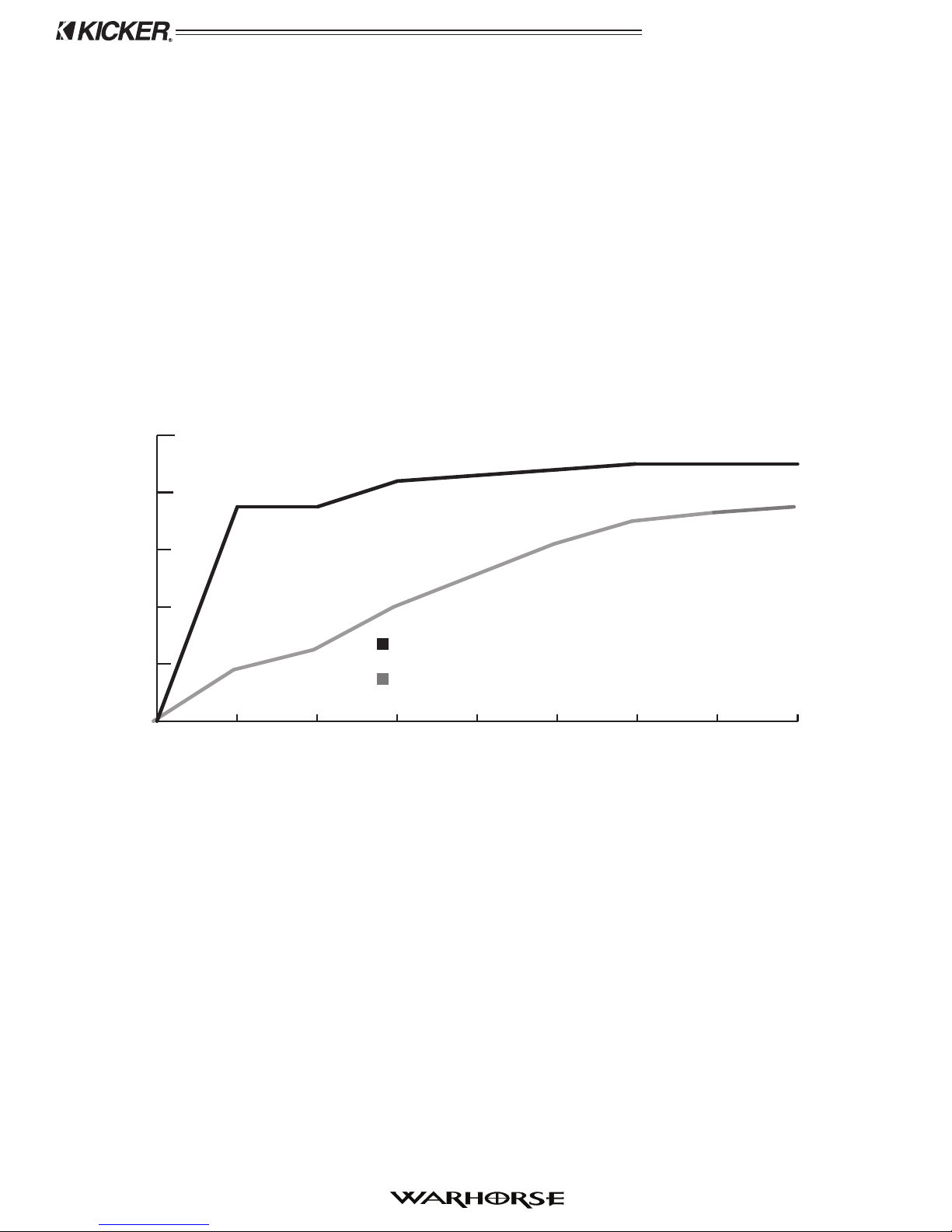
0
20
40
60
80
100
%EFFICIENCY
KICKER PATENT PENDING SIGNAL-MODULATED DESIGN
HIGH QUALITY CLASS D DESIGN
POWER OUTPUT (KW)
0.1 0.2 0.5 1.0 2.0 4.0 8.0 10
90%
75%
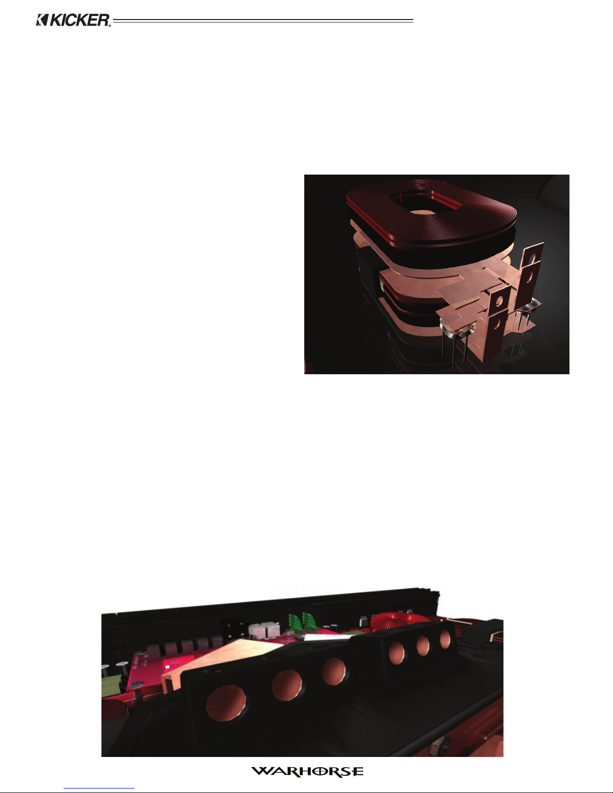
The Kicker Warhorse amplifier was specifically designed for competition car audio. Sporting 10,000
RMS watts of pure Kicker power, the ultra-high-efficiency design of the WX amplifier revolutionizes
traditional methods of amplification. While most amplifiers use a power supply combined with an
amplification circuit to amplify the audio signal, the Warhorse skips a step by amplifying the audio
signal directly from its patent pending signal-modulated power supply. The signal-modulated power
supply amplifies each polarity of the audio signal separately through its two voice coil outputs to
optimally drive dual-voice coil subwoofers and provide a competitive edge in SPL contests. From gold
plated power connectors and low profile planar transformers to the latest Texas Instruments DSP
technology, no expense was spared to make the Warhorse the most powerful and efficient mono
amplifier in mobile audio.
Installation
. . . as easy as 1, 2, 3
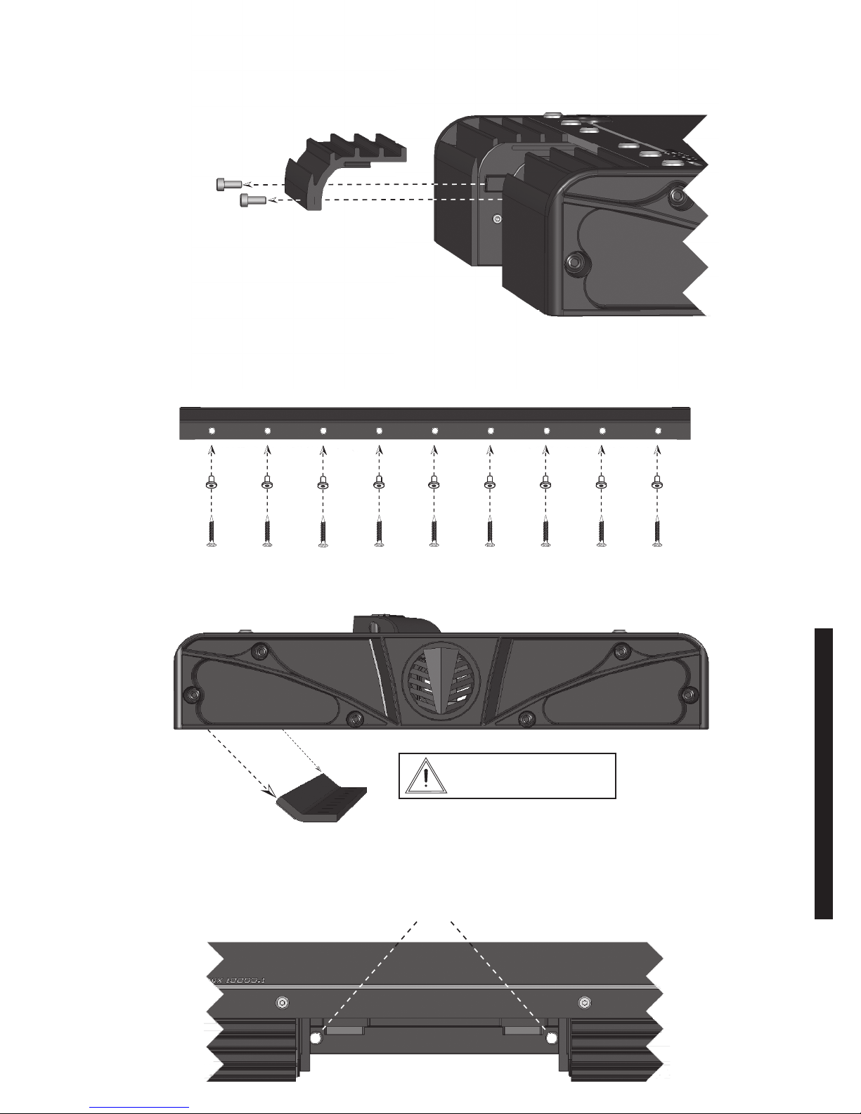
1. Mounting Choose a structurally sound location to mount your Kicker amplifier. The amplifier should
be mounted as close as possible to the battery network and be electrically isolated from the vehicle
ground. The distance from the battery network to the amplifier should not exceed 48” (122cm). It is
important to mount the amplifier before running any wires or supplying power to the amplifier. The
amplifier secures to the vehicle with an insertable mounting bracket used in combination with two
mounting holes located on the bottom plate of the control panel. You are solely responsible for securely
fastening the WX amplifier in your vehicle.
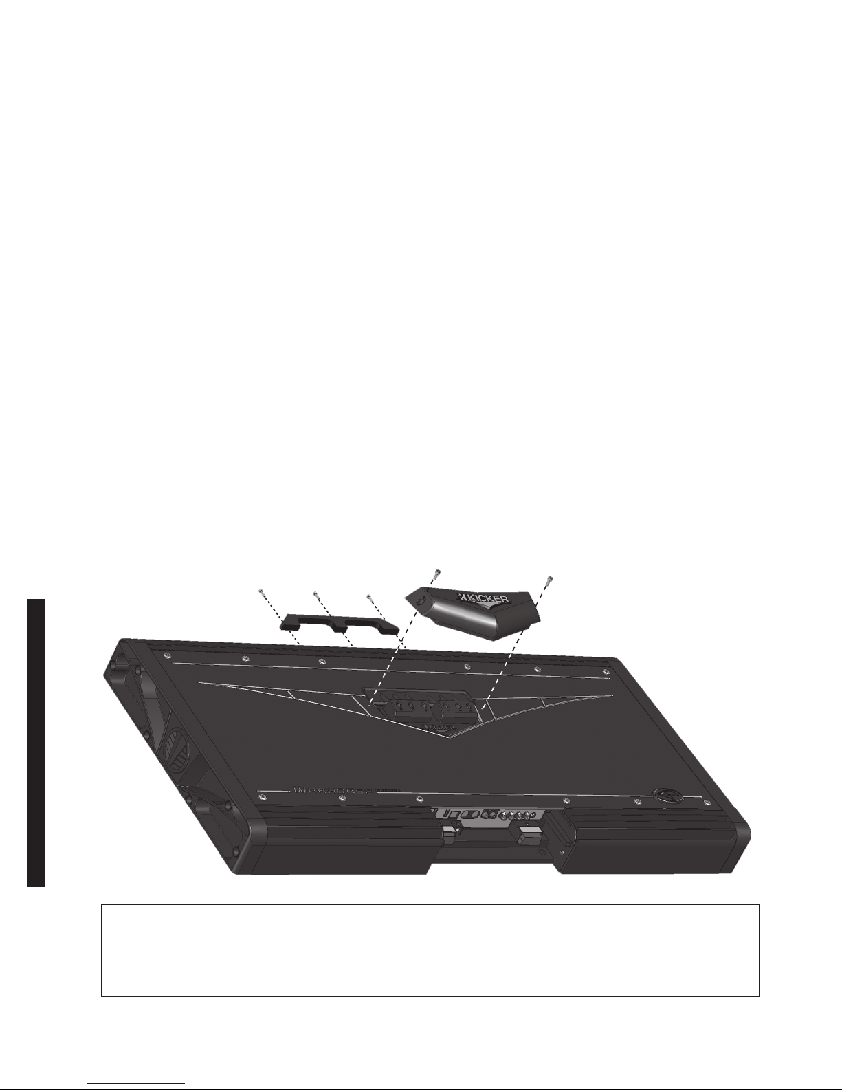
Before mounting the amplifier, the control panel shield must be removed. The control panel should
remain accessible for adjustment, leaving enough room to access the mounting holes and remove or
attach the control panel shield. Make sure there are no items behind the area where the screws will be
driven. Choose a location that allows at least 4” (10cm) of open ventilation for the amplifier. After
choosing the best location, secure the mounting bracket to the vehicle. Use the bracket as a template
to drill nine (9) holes with a 3/16” (4.8mm) bit into the appropriate locations. Attach the bracket to the
mounting location with the nine (9) supplied #10 (5mm) screws inserted through the nine (9) included
screw insulators.
Next, slide the amplifier over the mounting bracket and into the mounting slot. Make sure the mounting
bracket is properly inserted into the mounting slot and locate the two mounting holes on the bottom
plate of the control panel. Use the mounting holes as a template and drill two (2) holes using a 3/16”
(4.8mm) bit into the appropriate locations. Secure the bottom plate of the control panel with the two (2)
#10 (5mm) screws.
Caution The Kicker WX amplifier outputs extremely high voltage signals
from the voice coil (speaker) outputs and can cause serious injury or death
from electrocution. It is imperative to read the manual carefully and follow all
of the recommended safety precautions before installing the WX amplifier.
The patent pending signal-modulated
design of the Warhorse amplifier is the
most powerful and efficient design
available in mobile audio, rated at 90%
efficiency at full power with a 2 ohm load.
The graph compares the Warhorse
amplifier’s efficiency ratings to those of
industry standard Class D amplifiers.
Figure 1
Model:
SubwooferAmplifier
WX10000.1
5