6
ElectronicsLimitedWarranty
Kicker warrants this product
to
be free from defects
in
material and workmanship under normal use for aperiod of
THREE
(3)
MONTHS from date of original purchase with receipt. When purchased from an Authorized KICKER Dealer
it
is
warranted for TWO
(2)
YEARS from date of original purchase with receipt.
In
all
cases you must have the original
receipt. Should service be necessary under this warranty for any reason due to manufacturing defect
or
malfunction
during the warranty period, Kicker will repair or replace
(at
its discretion) the defective merchandise with equivalent
merchandise at no charge. Warranty replacements may have cosmetic scratches and blemishes. Discontinued
products may be replaced with more current equivalent products.
This warranty
is
valid only for the original purchaser and
is
not extended to owners
of
the product subsequent to the
original purchaser. Any applicable implied warranties are limited
in
duration to aperiod of the express warranty as
provided herein beginning with the date of the original purchase at retail, and no warranties, whether express
or
implied, shall apply to this product thereafter. Some states
do
not allow limitations on implied warranties; therefore
these exclusions may not apply to you. This warranty gives you specific legal rights; however you may have other
rights that vary from state
to
state.
WHAT TO DO IF YOU NEED WARRANTY OR SERVICE
Defective merchandise should be returned
to
your local Authorized Stillwater Designs (Kicker) Dealer for warranty
service. Assistance
in
locating
an
Authorized Dealer can be found at www.kicker.com
or
by contacting Stillwater
Designs directly.
You
can confirm that adealer
is
authorized by asking to see acurrent authorized dealer window
decal.
If
it becomes necessary for you to return defective merchandise directly to Stillwater Designs (Kicker), call the Kicker
Customer Service Department at (405)
624-8510
for aReturn Merchandise Authorization (RMA) number. Package
all
defective items
in
the original container
or
in
apackage that will prevent shipping damage, and return to:
Stillwater Designs, 5021 North Perkins Road, Stillwater, OK 74075
The RMA number must be clearly marked on the outside
of
the package. Please return only defective components.
The return
of
functioning items increases your return freight charges. Non-defective items will be returned freight-
collect to you.
Include acopy
of
the original receipt with the purchase date clearly visible, and a"proof-of-purchase" statement listing
the Customer's name, Dealer's name and invoice number, and product purchased. Warranty expiration on items
without proof-of-purchase will be determined from the type of sale and manufacturing date code. Freight must be
prepaid; items sent freight-collect, or COD, will be refused.
WHAT IS NOT COVERED?
This warranty
is
valid only if the product
is
used for the purpose for which it was designed.
It
does not cover:
oDamage due to improper installation
oSubsequent damage to other components
oDamage caused by exposure to moisture, excessive heat, chemical cleaners, and/or UV radiation
oDamage through negligence, misuse, accident
or
abuse. Repeated returns for the same damage may be
considered abuse
oAny cost or expense related to the removal
or
reinstallation of product
oSpeakers damaged due to amplifier clipping
or
distortion
oItems previously repaired or modified by any unauthorized repair facility
oReturn shipping on non-defective items
oProducts with tampered or missing barcode labels
oProducts returned without aReturn Merchandise Authorization
(RMA)
number
oFreight Damage
oThe cost
of
shipping product to Kicker
oService performed by anyone other than Kicker
HOW
LONG WILL IT TAKE?
Kicker strives to maintain agoal of 72-hour service for
all
electronics (amplifiers, crossovers, equalizers, etc.) returns.
Delays may be incurred if lack
of
replacement inventory or parts
is
encountered.
Failure to follow these steps may void your warranty. Any questions can be directed
to
the Kicker Customer Service
Department at (405) 624-851
O.
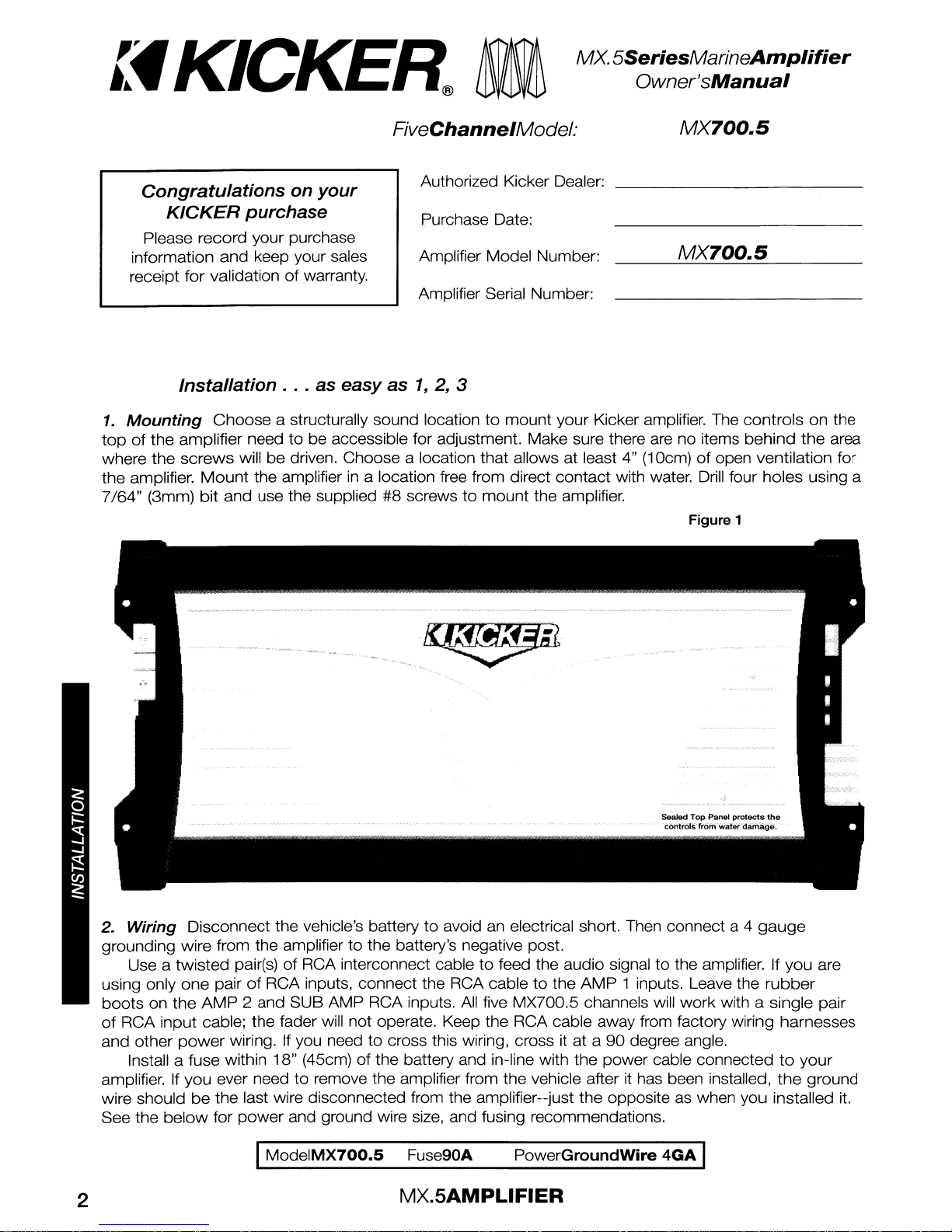
MX.5AMPLIFIER