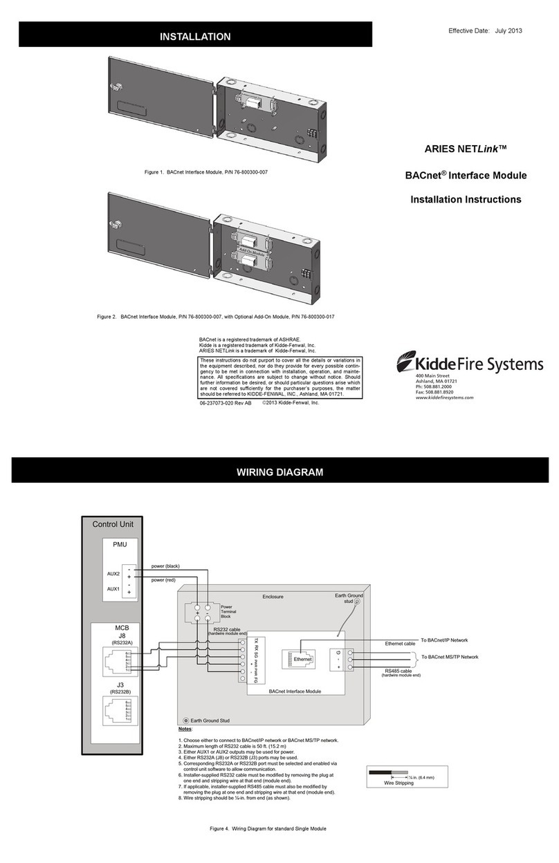
Kidde Fire Systems ARIES NETLink User manual

O
F
F
I
C
E
O
F
STATE FIRE MARSHAL
P/N 06-237058-001
February 2012
ARIES NETLinkTM
Intelligent Fire Alarm-Suppression
Control Unit
Installation, Operation, and
Maintenance Manual
FM Approvals
Project ID 3038124 UL Listing File
No. S2422
Californi a O f f i c e of
Stat e F ire M arsha l
Ce r t i ficat e o f A p p roval
No. 7165-1076:0195
New York City Fire Department
C e r t i f i c a t e o f A p p r o v a l
No. 6092


P/N 06-237058-001 i February 2012
FOREWORD
Note: This Manual, P/N 06-237058-001, is to be used by qualified and factory-trained personnel, knowledgeable
of NFPA standards and any other applicable standards in effect.
This Manual is intended to provide guidance to qualified technical professionals for the installation, operation and
maintenance of the ARIES NETLinkTM Intelligent Fire Alarm-Suppression Control Unit.
Only qualified persons experienced and trained in the installation of this type of equipment should install and
configure the ARIES NETLink. They must be familiar and experienced with the wiring diagrams and components,
electrical installation, and familiar not only with NEC, relevant NFPA and local codes but also trained and qualified
by Kidde-Fenwal, Inc. Kidde-Fenwal, Inc. is a manufacturer of the components that make up the ARIES NETLink
system, and may not have the opportunity to visit the sites where the product is installed or intended to be
installed. It is the responsibility of the professional installer (described above) to properly install and configure
the systems. Under no circumstances will Kidde-Fenwal, Inc. be liable for improper installation or configuration
of the systems.
The technical data contained herein is provided for informational purposes only, and should not be used as a
substitute for professional judgment. Although, Kidde-Fenwal, Inc. believes this information to be true and correct,
it is published and presented without any guarantee or warranty whatsoever. Kidde-Fenwal, Inc. disclaims any
liability for any use of the data other than as set out in this manual, foreword included.
Any questions concerning the information presented in this manual should be addressed to:
Kidde-Fenwal, Inc.
400 Main Street
Ashland, MA 01721, USA
Phone: (508) 881-2000
Toll Free: (800) 872-6527
Technical Support: (866) 287-2531
Fax: (508) 881-8920
www.kiddefiresystems.com

February 2012 ii P/N 06-237058-001
TERMS AND ABBREVIATIONS
°C °Centigrade LCD: Liquid Crystal Display
°F °Farenheit LED: Light Emitting Diode
A: Ampere MCB Main Controller Board
AC: Alternating Current NAC: Notification Appliance Circuit
ADA: Americans with Disabilities Act N.C.: Normally Closed
AH: Ampere Hour NEC: National Electrical Code
AHJ: Authority Having Jurisdiction NFPA: National Fire Protection Association
AI: Addressable Contact Input Device N.O.: Normally Open
AO: Addressable Relay Output Device NR: Not registered
ARC: Automatic Release Circuit NYC: New York City
AWG: American Wire Gauge PAS: Positive Alarm Sequence
CSFM: California State Fire Marshal PC: Personal Computer
DC: Direct Current PCB: Printed Circuit Board
DET: Detector pF: Pico-farads
EOC: Event Output Control P/N: Part Number
EOLD: End of Line Device PSU: Power Supply Unit
EOLR: End of Line Resistor RAM: Random Access Memory
FM: Factory Mutual RDCM: Remote Display Control Module
ft.: Feet R-NAC: Release-Notification Appliance Circuit
HSSD: High Sensitivity Smoke Detector RTC: Real Time Clock
Hz: Hertz (Frequency) SLC: Signaling Line Circuit
in.: Inch TB: Terminal Block
I/O Input/Output UL/ULI: Underwriter Laboratories, Inc.
IRI: Industrial Risk Insurers V: Volts
Vac: Vo l ts AC
Vdc: Volts DC
VRMS: Volts Root Mean Square

P/N 06-237058-001 iii February 2012
SAFETY SUMMARY
WARNING AND CAUTION DEFINITIONS
This section defines the safety conventions used throughout this manual (“WARNING” and “CAUTION”). Review
the definitions below to familiarize yourself with what these conventions mean and why and when they are used.
Installation Precautions Adherence to the following will aid in problem-free installation with long-term
reliability:
Note: This entire manual must be read and understood before installation.
This system meets FM and ANSI/UL 864 requirements for operation at 32° to 120°F (0 to 49°C) and at a relative
humidity of 93% (non-condensing) @ 90°F (32.2°C). However, the useful life of the system’s standby batteries and
the electronic components may be adversely effected by continuous operation at these environmental limits.
Therefore, it is recommended that this system and its peripherals be installed in an environment with a nominal
room temperature of 60-80°F.
Like all solid state electronic devices, this system may operate erratically or can be damaged when subjected to
lightning induced transients. Although no system is completely immune from lightning transients and interference,
proper grounding will reduce susceptibility. The use of overhead or outside aerial wiring is not
recommended due to the increased susceptibility to nearby lightning strikes. Consult with the Technical
Support Department if any problems are anticipated or encountered.
Do not install electronic assemblies prior to mounting and attaching conduit for field wiring to the enclosure.
Before making modifications, verify that they will not interfere with battery and printed circuit board locations. Do
not overtighten screw terminals. Overtightening may damage threads, resulting in reduced terminal contact
pressure and difficulty with screw terminal removal.
This system contains static-sensitive components. Always ground yourself with a proper wrist strap before
handling any circuits so that static charges are removed from the body. Use static suppressive packaging to protect
electronic assemblies removed from the control unit.
WARNING
Indicates an imminently hazardous situation which, if not avoided, could result in death,
serious bodily injury and/or property damage.
CAUTION
Indicates a potentially hazardous situation which, if not avoided, could result in property
or equipment damage.
WARNING
Several different sources of power can be connected to this fire alarm control unit.
Disconnect all sources of power before servicing. control unit and associated equipment
may be damaged by servicing while the unit is energized. Do not attempt to install,
service, or operate this control unit until this manual is read and understood.
CAUTION
System Re-acceptance Test after Re-Programming:
To ensure proper system operation, this system must be retested in accordance with
NFPA 72 after any programming change. Re-acceptance testing is also required after any
addition or deletion of system components, and after any modification, repair or
adjustment to system hardware or wiring.
All components, circuits and system operations known to be affected by a change must be
100% tested. In addition, to ensure that other operations are not inadvertently affected, at least
10% of initiating devices that are not directly affected by the change, up to a maximum of 50
devices, must also be tested and proper system operation verified.

February 2012 iv P/N 06-237058-001
Any communication wiring which exits the building or facility should not be routed to or located inside the same
conduit as the AC power.
Follow the instructions in this manual. These instructions must be followed to avoid damage to the control unit
and associated equipment. System operation and reliability depend upon proper installation.
Fire Alarm System Limitations While installing a fire alarm system may make lower insurance
rates possible, it is not a substitute for fire insurance!
An automatic fire alarm system – typically made up of smoke detectors, heat detectors, manual pull stations, notification
appliances, and a fire alarm control unit with remote-notification capability – can provide early warning of a developing
fire. Such a system, however, does not assure protection against property damage or loss of life resulting from a fire.
Any fire alarm system may fail for a variety of reasons:
Smoke detectors may not sense fire where smoke cannot reach the detectors such as in chimneys, in walls, on
roofs, or on the other side of closed doors. Smoke detectors on one level also may not sense a fire on another level
or floor of a building. A second floor detector, for example, may not sense a first floor or basement fire.
Furthermore, all types of smoke detectors, both ionization and photoelectric types, have sensing limitations. No type of
smoke detector can sense every kind of fire caused by carelessness and safety hazards such as smoking in bed, violent
explosions, escaping gas, improper storage of flammable materials, overloaded electrical circuits, children playing with
matches, or arson.
Notification appliances, such as bells, may not alert people if these appliances are located on the other side of
closed or partly open doors or are located on another floor of a building.
A fire alarm system will not operate without electrical power. If AC power fails, the system will operate from
standby batteries only for a specified time.
Rate-of-Rise heat detectors may be subject to reduced sensitivity over time. For this reason, the rate-of-rise feature
of each detector should be tested by a qualified fire protection specialist as recommended in NFPA 72.
Auxiliary Equipment used in the system may not be technically compatible with the control unit. It is essential to
use only equipment listed for service with your control unit.
The most common cause of fire alarm malfunctions, however, is inadequate maintenance. All devices and system
wiring should be tested and maintained by professional fire alarm installers following written procedures supplied
with each device. System inspection and testing should be scheduled monthly or as required by national and/or
local fire codes. Adequate written records of all inspections should be kept.
GENERAL SAFETY NOTICES The following must be observed to maintain personnel safety.
The following general safety notices supplement specific warnings and cautions appearing in the manual. The
safety precautions in this section must be understood and applied during operation and maintenance. This
manual is to be used by trained distributors/technicians. The entire manual should be read and fully understood
prior to installation.
FIRST AID
Any injury, no matter how slight, should never go unattended. Always obtain first aid or medical attention
immediately.

P/N 06-237058-001 v February 2012
GENERAL PRECAUTIONS
The following general safety precautions are to be observed at all times:
1. All electrical components associated with equipment shall be installed and grounded in accordance with
NEC and local regulatory requirements.
2. Special precautionary measures are essential to prevent applying power to equipment at any time
maintenance work is in progress.
3. Before working on electrical equipment, use a voltmeter to ensure that system is not energized.
4. When working near electricity, do not use metal rulers, flashlights, metallic pencils, or any other
objects having exposed conductive material.
5. When connecting a meter to terminals for measurement, use a voltage range higher than expected voltage to
be measured.
NOTICE TO USERS, INSTALLERS, AUTHORITIES
HAVING JURISDICTION AND ALL OTHER INVOLVED PARTIES
This product incorporates field-programmable software. In order for this product to comply with the requirements
in the Standard Control Units and Accessories for Fire Alarm Systems, ANSI/UL 864, certain programming
features or options must be limited to specific values or not used at all as indicated below.
1.) Abort switches may be set up to operate in any of the following ways:
Abort Mode 1*(UL) - Count down to 10 seconds and hold. Resume countdown at 10 seconds.
Abort Mode 2 (Reset) - Reset to initial delay setting. Resume countdown for entire delay period.
Abort Mode 3 (IRI) - Same as Mode 1, except disable abort function if countdown timer has started.
Abort Mode 4 (NYC) - Resets to 120 seconds.
Abort Mode 5 - Disables the abort.
*NOTE:Only Abort Mode 1 is ANSI/UL 864 compliant.
2.) Event Acknowledgement:
*NOTE: Global Acknowledge is not ANSI/UL 864 compliant.
3.) Programmable Alarm Verification:
Programmable Alarm Verification period must be a maximum of 60 seconds to meet ANSI/UL 864
requirements.

February 2012 vi P/N 06-237058-001
Note: The following notice applies to the Digital Alarm Communicator Transmitter (DACT) card
(P/N 76-800015-001).
NOTICE
FCC Part 68 Information - Applies to DACT Options
1. This equipment complies with Part 68 of the Federal Communication Commission (FCC) rules. This unit
bears a label which contains, among other information, the FCC registration number and ringer equivalence
number (REN) for this equipment. If requested, this information must be provided to the telephone
company.
2. This equipment contains an FCC compliant modular jack. It is designed to be connected to the telephone
network or premises wiring using compatible modular plugs and cabling which comply with the
requirements of FCC Part 68 rules.
3. This equipment is alarm dialing equipment (equipment code “AL”) which must be able to seize the telephone
line and place a call in an emergency situation. It must be able to do this even if other equipment (telephone,
answering system, computer modem, etc.) already has the telephone line in use. To do so, alarm dialing
equipment must be connected to a properly installed RJ45X jack that is electrically in series with and ahead
of all other equipment attached to the same telephone line.
4. The Ringer Equivalence Number, or REN, is used to determine the number of devices which may be
connected to the telephone line. Excessive RENs on a telephone line may cause the equipment to not ring in
response to an incoming call. In most but not all areas, the sum of the RENs of all equipment on a line
should not exceed five (5.0). To be certain of the number of devices that may be connected to a line, as
determined by the total RENs, contact the local telephone company. The REN for this product is part of the
product identifier that has the format “US:AAAEQ##TXXXX”. The digits represented by “##” are the REN
without a decimal point (for example,“03” is a REN of “0.3”).
5. In the unlikely event that this equipment causes harm to the telephone network, the telephone company will
notify you in advance that temporary discontinuance of service may be required. But if advance notice is not
practical, the telephone company will notify you as soon as possible. Also, you will be advised of your right
to file a complaint with the FCC if you believe it is necessary.
6. From time to time, the telephone company may make changes in its facilities, equipment, operations or
procedures which could affect the operation of this equipment. If this occurs, the telephone company will
provide advance notice in order for you to make the modifications necessary to maintain uninterrupted
service.
7. If trouble is experienced with this equipment, repair and warranty information can be obtained in the U.S.
from Kidde-Fenwal, Inc. at: +1 (508) 881-2000. If the equipment is causing harm to the telephone network,
the telephone company may request that you disconnect the equipment until the problem is resolved.
8. This equipment must not be used on party lines.

P/N 06-237058-001 vii February 2012
Table of Contents
Foreword............................................................................................................................i
Terms and Abbreviations ...................................................................................................ii
Safety Summary ................................................................................................................. iii
Table of Contents................................................................................................................ vii
List of Figures.....................................................................................................................xiii
List of Tables...................................................................................................................... xvii
CHAPTER 1 GENERAL INFORMATION
1-1 Introduction............................................................................................................ 1-1
1-2 Listings and Approvals ........................................................................................... 1-1
1-3 Codes and Standards.............................................................................................. 1-1
1-3.1 Suppression System Standards .............................................................................. 1-2
1-3.2 Other Standards ..................................................................................................... 1-2
1-4 System Description................................................................................................. 1-3
1-5 System Components ............................................................................................... 1-4
1-6 Optional Components ............................................................................................. 1-4
1-7 System Enclosure Types ......................................................................................... 1-4
1-7.1 Enclosure Features ................................................................................................. 1-5
1-8 Keypad And Display................................................................................................ 1-9
1-8.1 Keypad/Display Features......................................................................................... 1-9
1-9 Main Controller Board (MCB) ................................................................................. 1-10
1-9.1 Main Controller Board Features ............................................................................. 1-11
1-10 Power Supply/PMU Assembly.................................................................................. 1-11
1-10.1 Power Supply Units ................................................................................................ 1-12
1-10.2 Power Management Unit (PMU) Board .................................................................... 1-12
1-11 Batteries ................................................................................................................. 1-13
1-12 Expansion Card Cage.............................................................................................. 1-14
1-12.1 Expansion Backplane ............................................................................................. 1-14
1-13 Optional Expansion Cards ...................................................................................... 1-16
1-13.1 General Guidelines for the Use of Expansion Cards................................................ 1-16
1-13.2 Expansion Card Slot Addresses.............................................................................. 1-16
1-14 Optional Remote Devices ........................................................................................ 1-21
1-14.1 Remote Devices Using RS232 or USB Ports............................................................ 1-21
1-14.2 Remote Devices Using RS485 Bus to MCB.............................................................. 1-22
1-15 Signaling Line Circuit (SLC) Devices and Modules.................................................. 1-25
1-15.1 SmartOne® Devices................................................................................................ 1-25
1-16 High Sensitivity Smoke Detectors ........................................................................... 1-26
1-17 SmartOne Addressable Modules ............................................................................. 1-27
1-18 Optional Software ................................................................................................... 1-30
1-18.1 Remote Configuration Software .............................................................................. 1-30
1-19 System Specifications ............................................................................................. 1-31
TABLE OF CONTENTS

Table of Contents
February 2012 viii P/N 06-237058-001
TABLE OF CONTENTS (CONT.)
CHAPTER 2 INSTALLATION
2-1 Introduction ............................................................................................................2-1
2-2 Preparing for Installation.........................................................................................2-1
2-2.1 Unpacking the System.............................................................................................2-1
2-2.2 Materials/Tools Required ........................................................................................2-2
2-2.3 Determining Wall Location ......................................................................................2-2
2-2.4 Removing Knockouts From Enclosure ....................................................................2-2
2-2.5 Installing Conduit....................................................................................................2-3
2-2.6 Installing Electrical Boxes .......................................................................................2-3
2-3 Overview of Installation Steps..................................................................................2-3
2-3.1 Step One: Shut Off AC Power ..................................................................................2-3
2-3.2 Step Two: Prepare the Enclosure and Electrical Wiring ..........................................2-3
2-3.3 Step Three: Mount the Enclosure ............................................................................2-3
2-3.4 Step Four: Install the Top Tier Power Supply/PMU Assembly and MCB..................2-3
2-3.5 Step Five: Install Expansion Card Cage and Included Cards (if applicable) .............2-3
2-3.6 Step Six: Install Batteries ........................................................................................2-4
2-3.7 Step Seven: Install Expansion Enclosures and/or Remote Modules (if applicable)...2-4
2-3.8 Step Eight: Auto-configuring the System..................................................................2-4
2-3.9 Step Nine: Uploading the Configuration File and Performing the Pre-Test...............2-4
2-3.10 Step Ten: Performing Final System Test and Commissioning the System ...............2-4
2-3.11 Step Eleven: Installing the Actuation Devices and Extinguishing System .................2-4
2-3.12 Step Twelve: Performing Final Installation Procedures............................................2-4
2-4 Standard System Installation Procedure .................................................................2-5
2-4.1 Surface Mounting of Main or Expansion Enclosures ...............................................2-5
2-4.2 Semi-Flush Mounting of Main or Expansion Enclosures .........................................2-6
2-4.3 Installing A Power Supply Unit into The Enclosure Top Tier ..................................2-8
2-4.4 Installing the Power Management Unit (PMU) Board into Enclosure Top Tier.........2-9
2-4.5 Connecting the Audible PMU Trouble Sounder Harness..........................................2-13
2-4.6 Making AC Power Source and Earth Ground Connections ......................................2-13
2-4.7 Installing the Main Controller Board into Enclosure Top Tier.................................2-16
2-4.8 Replacing Enclosure Door .......................................................................................2-18
2-5 Making Internal 24Vdc Power Connections .............................................................2-19
2-6 Making Internal Communication Connections.........................................................2-20
2-7 Optional Equipment Installation Procedure ............................................................2-21
2-7.1 Installing the Expansion Card Cage ........................................................................2-21
2-7.2 Inserting and Securing an Expansion Card .............................................................2-23
2-7.3 Installing Add-On Power Supply/PMU Assembly With Bracket ................................2-24
2-7.4 Installing the Battery Tray .......................................................................................2-25
2-7.5 Connecting Standby Batteries To PMU Board .........................................................2-26
2-8 Setting Up Wiring To Field Devices..........................................................................2-27
2-8.1 Installing Electrical Wiring and Making Connections...............................................2-27
2-8.2 Overview of SLC Wiring Styles.................................................................................2-27
2-8.3 Electrical Supervision .............................................................................................2-27
2-8.4 Wiring Auxiliary Power Outputs ..............................................................................2-28
2-8.5 Wiring Signaling Line Circuits .................................................................................2-28
2-8.6 Wiring Notification Appliance Circuits .....................................................................2-34
2-8.7 Wiring R-NAC (Combination) Circuits .....................................................................2-36

P/N 06-237058-001 ix February 2012
Table of Contents
TABLE OF CONTENTS (CONT.)
2-8.8 Relay Outputs ......................................................................................................... 2-39
2-8.9 City Tie Wiring ........................................................................................................ 2-40
2-9 Digital Alarm Communicator Transmitter (DACT) Wiring....................................... 2-41
2-10 Internet Communications Module (ICM) Wiring ...................................................... 2-42
2-11 Setting Up RS232 / USB Communications.............................................................. 2-43
2-11.1 Setting up RS232 Communications Port................................................................. 2-43
2-11.2 Setting up USB Communications Ports................................................................... 2-44
2-11.3 Connecting a Laptop, Remote Computer or Printer ................................................ 2-44
2-12 Setting Up Remote RS485 Peripheral Devices And Enclosures ............................... 2-45
2-12.1 Installing the Remote Enclosure ............................................................................. 2-46
2-12.2 Installing the ATM-L Annunciator Driver Module.................................................... 2-50
2-12.3 Installing the ATM-R Relay Driver Module .............................................................. 2-50
2-13 Setting Up Network Equipment .............................................................................. 2-50
2-13.1 Network Interface Card (NIC).................................................................................. 2-50
2-14 Installing The Fiber Optic Converter Module (FOCM) ............................................. 2-52
2-14.1 Fiber Optic Converter Module (FOCM) Wiring - Single Channel .............................. 2-53
2-14.2 Fiber Optic Converter Module (FOCM) Wiring - Dual Channel ................................ 2-54
2-15 Installing the Large Capacity Battery Cabinet.......................................................... 2-55
CHAPTER 3 CONFIGURATION AND PROGRAMMING
3-1 Introduction............................................................................................................ 3-1
3-1.1 Initial Signaling-Line Circuit Configuration ............................................................. 3-1
3-1.2 Site-Specific Programming...................................................................................... 3-3
3-2 Menu Operation ...................................................................................................... 3-4
3-3 Overview of Main Menu Functions .......................................................................... 3-4
3-3.1 ISOLATE Menu Functions ...................................................................................... 3-6
3-3.2 LIST Menu Functions ............................................................................................. 3-12
3-3.3 SET Menu Functions .............................................................................................. 3-18
3-3.4 TEST Menu Functions ............................................................................................ 3-45
CHAPTER 4 OPERATION
4-1 Introduction............................................................................................................ 4-1
4-2 Operating States ..................................................................................................... 4-1
4-2.1 The Event Output Control (EOC) Program.............................................................. 4-2
4-3 User Interface Keys and Functions.......................................................................... 4-2
4-4 Operator Control Keys ............................................................................................ 4-3
4-4.1 User Interface Button Operations............................................................................ 4-4
4-5 Alphanumeric Keypad............................................................................................. 4-5
4-6 Status-Indicating LEDs ........................................................................................... 4-6
4-7 LCD Panel System Status Messages ........................................................................ 4-7
4-8 Using Passwords For System Security .................................................................... 4-7
4-8.1 Levels of Security.................................................................................................... 4-7
4-8.2 Default Passwords .................................................................................................. 4-8
4-8.3 Entering Passwords ................................................................................................ 4-8
4-9 System Startup Procedure ...................................................................................... 4-8
4-9.1 Preliminary Procedures .......................................................................................... 4-8
4-9.2 Initial Power-Up ...................................................................................................... 4-9
4-10 ARIES NETLink System Operation Overview.......................................................... 4-12

Table of Contents
February 2012 x P/N 06-237058-001
TABLE OF CONTENTS (CONT.)
4-10.1 Normal Operation ...................................................................................................4-12
4-10.2 Trouble State ..........................................................................................................4-12
4-10.3 Alarm State .............................................................................................................4-14
4-10.4 Supervisory State ....................................................................................................4-19
4-10.5 Pre-Alarm State .......................................................................................................4-20
4-10.6 Concurrent States ...................................................................................................4-22
CHAPTER 5 NETWORKING
5-1 Network System Operation......................................................................................5-1
5-2 Communications .....................................................................................................5-3
5-3 Network Event Broadcasts ......................................................................................5-3
5-4 Operator Control.....................................................................................................5-3
5-5 Event Recording ......................................................................................................5-4
5-6 Event Output Control (EOC)....................................................................................5-4
5-7 Configuration Uploads/Downloads ..........................................................................5-4
5-8 Menu Routines ........................................................................................................5-4
5-8.1 Accessing Remote Nodes Via Keypad.......................................................................5-5
5-8.2 Network Groups......................................................................................................5-5
5-8.3 Operating States......................................................................................................5-10
5-8.4 Operator Control Keys.............................................................................................5-11
5-8.5 Status-Indicating LEDs............................................................................................5-11
5-8.6 Network Display Messages ......................................................................................5-11
5-8.7 Remote Trouble Events ...........................................................................................5-11
5-8.8 Remote Alarm Events ..............................................................................................5-12
5-8.9 Remote Positive-Alarm-Sequence (PAS) Events .......................................................5-13
5-8.10 Remote Alarm-Verification Events ...........................................................................5-13
5-8.11 Remote Supervisory Events.....................................................................................5-14
5-8.12 Remote Pre-Alarm Events........................................................................................5-15
5-8.13 How Concurrent Remote Events Will Be Displayed .................................................5-16
5-8.14 Network Start-Up ....................................................................................................5-19
CHAPTER 6 TESTING AND MAINTENANCE
6-1 Introduction ............................................................................................................6-1
6-2 Semi-Annual and Annual Testing ............................................................................6-1
6-2.1 Lamp Test ...............................................................................................................6-1
6-2.2 Battery Test.............................................................................................................6-1
6-2.3 Initiating-Devices Test .............................................................................................6-2
6-2.4 Walk Test ................................................................................................................6-2
6-3 MCB Clock Battery Replacement .............................................................................6-2
6-4 Testing Frequency ...................................................................................................6-3
6-5 Fuse Replacement ...................................................................................................6-3
CHAPTER 7 TROUBLESHOOTING
7-1 Introduction ............................................................................................................7-1
CHAPTER 8 PARTS LIST
8-1 Available Parts.........................................................................................................8-1

P/N 06-237058-001 xi February 2012
Table of Contents
TABLE OF CONTENTS (CONT.)
APPENDIX A— Battery and Power Supply Calculations ...................................................................A-1
APPENDIX B— Wiring Requirements for ARIES NETLink Signaling Line Circuit.............................B-1
APPENDIX C— List of Agency Listed Compatible Devices ...............................................................C-1
APPENDIX D— FM Rules for Preaction/Deluge Systems ..................................................................D-1
APPENDIX E— Routings for Power-Limited and Non-Power-Limited Wiring ....................................E-1
APPENDIX F— ARIES NETLink For Canadian Applications ............................................................ F-1
F-1 Canadian Application-style Enclosures ................................................................... F-1
F-2 Installation.............................................................................................................. F-2
APPENDIX G— ARIES NETLink For City Of Chicago Applications...................................................G-1
G-1 Introduction............................................................................................................G-1
G-2 Overview of the Stand-Alone Control Box................................................................G-2
G-2.1 Fire Alarm Trouble .................................................................................................G-2
G-2.2 City Tie Trouble......................................................................................................G-2
G-2.3 City Disconnect Switch ...........................................................................................G-3
G-3 Installation and Connections...................................................................................G-3
G-3.1 Labeling ..................................................................................................................G-3
G-3.2 Field Wiring Connections ........................................................................................G-5
APPENDIX H— Conversion Instructions for PEGAsys ..................................................................... H-1
H-1 Introduction............................................................................................................H-1
H-2 Contents of PEGAsys Control Unit Retrofit Kit........................................................H-1
H-3 Optional parts (Not included in retrofit kit) ............................................................H-3
H-3.1 Parts for the Control Unit Bottom Tier....................................................................H-3
H-3.2 Additional ARIES NETLink Parts............................................................................H-3
H-4 Tools Required .......................................................................................................H-4
H-5 Preparation.............................................................................................................H-4
H-6 Procedure ...............................................................................................................H-4

Table of Contents
February 2012 xii P/N 06-237058-001
THIS PAGE INTENTIONALLY LEFT BLANK.

List of Figures
P/N 06-237058-001 xiii February 2012
Figure Name Page Number
1-1 Full ARIES NETLink Fire Suppression System Applications .................................................... 1-3
1-2 Illustration of Typical 3-Tiered Main Enclosure Configurations................................................ 1-6
1-3 Illustration of Typical 2-Tiered Main Enclosure Configurations................................................ 1-7
1-4 Large Expansion Enclosure (a) and Small Expansion Enclosure (b)......................................... 1-7
1-5 Illustration of Remote Enclosure ............................................................................................ 1-8
1-6 Keypad/Display ......................................................................................................................... 1-9
1-7 ARIES NETLink Main Controller Board Layout........................................................................ 1-10
1-8 Power Supply/PMU Assembly Layout ...................................................................................... 1-12
1-9 Power Management Unit (PMU) Board...................................................................................... 1-13
1-10 Expansion Card Cage ............................................................................................................. 1-14
1-11 ARIES NETLink Expansion Backplane..................................................................................... 1-15
1-12 Remote LED Annunciator Module ............................................................................................ 1-22
1-13 Remote Display Control Module (RDCM).................................................................................. 1-23
1-14 ATM Series Driver Module........................................................................................................ 1-23
1-15 Fiber Optic Converter Modules................................................................................................. 1-24
2-1 Mounting Dimensions for 3-Tiered (a) and 2-Tiered (b) Main and Expansion Enclosures ........ 2-5
2-2 Rough Openings for 3-Tiered (a) and 2-Tiered (b) Main and Expansion Enclosures................. 2-6
2-3 Semi-Flush Mounting of 3-Tiered and 2-Tiered Main & Expansion Enclosures ........................ 2-7
2-4 Power Supply Unit.................................................................................................................... 2-8
2-5 Installing A Power Supply Unit into the Enclosure Top Tier ................................................... 2-9
2-6 Installing A PMU Board into the Enclosure Top Tier ................................................................ 2-10
2-7 Connecting Power Supply Wiring Harness to PMU Board ......................................................... 2-11
2-8 Power Supply Wiring Harness Connections .............................................................................. 2-11
2-9 Wiring Diagram for Power Management Unit (PMU) Board....................................................... 2-12
2-10 Snap-On Suppression Filter Shown Installed Around Black and White AC Power Wires .......... 2-14
2-11 AC Connections to PMU Board ............................................................................................. 2-15
2-12 AC Voltage Protection Cover ................................................................................................... 2-15
2-13 Installing A Main Controller Board with Keypad/Display into the Enclosure Top Tier .............. 2-17
2-14 Wiring Diagram for Main Controller Board............................................................................... 2-18
2-15 Internal 24 Vdc Power Connections .......................................................................................... 2-19
2-16 Internal Communication Connections....................................................................................... 2-20
2-17 Installing the Expansion Card Cage ..........................................................................................2-22
2-18 Inserting an Expansion Card into Card Cage Slot ..................................................................... 2-23
2-19 Installing the Add-On Power Supply/PMU Assembly with Bracket ............................................ 2-24
2-20 Installing the Battery Tray into Bottom Tier ............................................................................. 2-25
2-21 Standby Battery Connections.................................................................................................... 2-26
2-22 Auxiliary Power Output Terminals............................................................................................2-28
2-23 Wiring Diagram for CLASS-A and CLASS-B Signaling Line Circuits ........................................ 2-30
2-24 Wiring Diagram for CLASS-A, Style 7 Signaling Line Circuit..................................................... 2-31
2-25 Measuring CLASS-B SLC Wiring Resistance ............................................................................. 2-32
2-26 Measuring CLASS-B SLC Wiring Capacitance........................................................................... 2-32
2-27 Measuring CLASS-A SLC Wiring Resistance ............................................................................. 2-33
2-28 Measuring CLASS-A SLC Wiring Capacitance........................................................................... 2-33
2-29 Wiring Diagram for Notification-Appliance Circuits .................................................................. 2-34
2-30 Wiring Length vs. Notification-Appliance Current ..................................................................... 2-35
2-31 Wiring Diagrams for Solenoid-Based Releasing Devices............................................................ 2-38
2-32 Relay Outputs Diagram............................................................................................................. 2-39
2-33 City Tie Wiring Diagram ........................................................................................................... 2-40
2-34 DACT Card Wiring Diagram ..................................................................................................... 2-41
2-35 ICM Card Wiring Diagram ........................................................................................................ 2-42
2-36 RS232 Communications Ports..................................................................................................2-43
LIST OF FIGURES

List of Figures
February 2012 xiv P/N 06-237058-001
LIST OF FIGURES (CONT.)
Figure Name Page Number
2-37 USB Communications Ports......................................................................................................2-44
2-38 Laptop/Remote Computer and Optional Printer Connections to MCB .......................................2-45
2-39 Surface Mounting of the Remote Enclosure (shown without RDCM or R-LAM modules) ...........2-47
2-40 Semi-Flush Mounting of Remote Enclosure (shown without RDCM or R-LAM modules)...........2-48
2-41 RS485 Wiring Diagram for Remote Devices to MCB..................................................................2-49
2-42 24 Vdc-Power Wiring Length vs. Peripheral-Devices Current.....................................................2-50
2-43 Network Interface Card Wiring..................................................................................................2-51
2-44 Mounting the FOCM Enclosure .................................................................................................2-52
2-45 Wiring Diagram For Single Channel FOCM ...............................................................................2-53
2-46 Wiring Diagram For Dual Channel FOCM .................................................................................2-54
2-47 Mounting Dimensions for Large Capacity Battery Box...............................................................2-55
3-1 Typical Device Not Registered Message .....................................................................................3-1
3-2 Password Prompt......................................................................................................................3-2
3-3 Top-Level Menu Selections........................................................................................................3-2
3-4 Set Menu...................................................................................................................................3-2
3-5 Programming Sub-Menu ...........................................................................................................3-2
3-6 Typical Auto-Learn In-Process Display......................................................................................3-2
3-7 Typical Auto-Learn Complete Display .......................................................................................3-2
3-8 Main Menu Functions................................................................................................................3-4
3-9 ARIES NETLink Main Menu Functions .....................................................................................3-6
3-10 ARIES NETLink Isolate Menu Functions (Fig. 1 of 4)................................................................3-7
3-11 ARIES NETLink Isolate Menu Functions (Cont’d - Fig. 2 of 4)..................................................3-9
3-12 ARIES NETLink Isolate Menu Functions (Cont’d - Fig. 3 of 4)...................................................3-10
3-13 ARIES NETLink Isolate Menu Functions (Cont’d - Fig. 4 of 4)...................................................3-11
3-14 ARIES NETLink List Menu Functions (Fig. 1 of 5) ....................................................................3-12
3-15 ARIES NETLink List Menu Functions (Cont’d - Fig. 2 of 5).......................................................3-14
3-16 ARIES NETLink List Menu Functions (Cont’d - Fig. 3 of 5).......................................................3-15
3-17 ARIES NETLink List Menu Functions (Cont’d - Fig. 4 of 5).......................................................3-16
3-18 ARIES NETLink List Menu Functions (Fig. 5 of 5) ....................................................................3-17
3-19 ARIES NETLink Set Menu Functions (Fig. 1 of 18) ...................................................................3-18
3-20 ARIES NETLink Set Menu Functions (Cont’d - Fig. 2 of 18)......................................................3-19
3-21 ARIES NETLink Set Menu Functions (Cont’d - Fig. 3 of 18)......................................................3-21
3-22 ARIES NETLink Set Menu Functions (Cont’d - Fig. 4 of 18)......................................................3-23
3-23 ARIES NETLink Set Menu Functions (Cont’d - Fig. 5 of 18)......................................................3-24
3-24 ARIES NETLink Set Menu Functions (Cont’d - Fig. 6 of 18)......................................................3-26
3-25 ARIES NETLink Set Menu Functions (Cont’d - Fig. 7 of 18)......................................................3-27
3-26 ARIES NETLink Set Menu Functions (Cont’d - Fig. 8 of 18)......................................................3-29
3-27 ARIES NETLink Set Menu Functions (Cont’d - Fig. 9 of 18)......................................................3-33
3-28 ARIES NETLink Set Menu Functions (Cont’d - Fig. 10 of 18)....................................................3-35
3-29 ARIES NETLink Set Menu Functions (Cont’d - Fig. 11 of 18)....................................................3-36
3-30 ARIES NETLink Set Menu Functions (Cont’d - Fig. 12 of 18)....................................................3-38
3-31 ARIES NETLink Set Menu Functions (Cont’d - Fig. 13 of 18)....................................................3-39
3-32 ARIES NETLink Set Menu Functions (Cont’d - Fig. 14 of 18)....................................................3-40
3-33 ARIES NETLink Set Menu Functions (Fig. 15 of 18) .................................................................3-41
3-34 ARIES NETLink Set Menu Functions (Fig. 16 of 18) .................................................................3-42
3-35 ARIES NETLink Set Menu Functions (Fig. 17 of 18) .................................................................3-43
3-36 ARIES NETLink Set Menu Functions (Fig. 18 of 18) .................................................................3-44
3-37 ARIES NETLink Test Menu Functions (Fig. 1 of 5) ...................................................................3-45
3-38 ARIES NETLink Test Menu Functions (Cont’d - Fig. 2 of 5) ......................................................3-46
3-39 ARIES NETLink Test Menu Functions (Cont’d - Fig. 3 of 5) ......................................................3-48
3-40 ARIES NETLink Test Menu Functions (Cont’d - Fig. 4 of 5) ......................................................3-51
3-41 ARIES NETLink Test Menu Functions (Cont’d - Fig. 5 of 5) ......................................................3-53

List of Figures
P/N 06-237058-001 xv February 2012
LIST OF FIGURES (CONT.)
Figure Name Page Number
4-1 ARIES NETLink Keypad/Display............................................................................................... 4-2
4-2 Typical Multiple Level-2 Event-Type Display............................................................................. 4-7
4-3 Serial Number Request Message............................................................................................... 4-9
4-4 Remove Clock Battery Tab Message.......................................................................................... 4-9
4-5 Initial Power-Up Message.......................................................................................................... 4-9
4-6 Initialization Message................................................................................................................ 4-10
4-7 Boot-Up Message ...................................................................................................................... 4-10
4-8 Password Prompt ..................................................................................................................... 4-10
4-9 Top-Level Menu Selections ....................................................................................................... 4-10
4-10 Set Menu .................................................................................................................................. 4-10
4-11 Time/Date Sub-Menu ................................................................................................................ 4-10
4-12 Sub-Menu for Time-Display Format ......................................................................................... 4-11
4-13 Sub-Menu to Enter Current Time ............................................................................................. 4-11
4-14 Sub-Menu to Complete Current-Time Entry ............................................................................. 4-11
4-15 Time Updated........................................................................................................................... 4-11
4-16 Time/Date Sub-Menu ................................................................................................................ 4-11
4-17 Sub-Menu to Enter Current Date ..............................................................................................4-11
4-18 Date Updated............................................................................................................................ 4-12
4-19 Normal Operation Display ........................................................................................................ 4-12
4-20 Typical Trouble Message Display.............................................................................................. 4-13
4-21 Typical Message After Manual Trouble Scroll Cycle .................................................................. 4-13
4-22 24-Hour Trouble Reminder Message ........................................................................................ 4-14
4-23 Typical Alarm Message Display................................................................................................. 4-14
4-24 Outputs Silenced Message ........................................................................................................ 4-15
4-25 Alarm Events Buffer Full Message ............................................................................................4-16
4-26 Typical PAS Message Display.................................................................................................... 4-17
4-27 PAS Acknowledgment Message ................................................................................................. 4-18
4-28 Typical Alarm Verification Message Display.............................................................................. 4-18
4-29 Alarm Verification Acknowledgment Message ........................................................................... 4-19
4-30 Typical Supervisory Message Display ....................................................................................... 4-19
4-31 Typical Pre-Alarm-Message Display .......................................................................................... 4-21
4-32 Outputs-Silenced Message ........................................................................................................ 4-21
4-33 Typical Countdown-to-Release Display ..................................................................................... 4-24
4-34 Typical Release Message ........................................................................................................... 4-25
4-35 Typical Display after Acknowledgment of Release Message....................................................... 4-25
4-36 Typical Display with Event Status............................................................................................. 4-25
4-37 Typical Display After Abort-Switch Operation........................................................................... 4-25
4-38 Typical Multiple Level-2 Event-Type Display............................................................................. 4-26
4-39 Lower-Level-Events-Buffer-Full Message ................................................................................... 4-27
5-1 Typical Networked ARIES NETLink System ............................................................................. 5-2
5-2 Network Node Prompt .............................................................................................................. 5-5
5-3 Top-level Menu Selections ........................................................................................................ 5-5
5-4 Group 0 Networked Control Unit Interactions .......................................................................... 5-7
5-5 Processing Group 0 Networked Control Unit Interactions ........................................................ 5-9
5-6 Network Normal Message Display............................................................................................. 5-10
5-7 Typical Remote-Trouble-Message Display................................................................................. 5-11
5-8 Typical Remote Alarm Message Display.................................................................................... 5-12
5-9 Typical Remote PAS Message Display....................................................................................... 5-13
5-10 Typical Remote Alarm-Verification Message Display................................................................. 5-14
5-11 Typical Remote Supervisory Message Display........................................................................... 5-15
5-12 Typical Remote Pre-Alarm Message Display.............................................................................. 5-15
5-13 Typical Network Release Message.............................................................................................5-16

List of Figures
February 2012 xvi P/N 06-237058-001
LIST OF FIGURES (CONT.)
Figure Name Page Number
5-14 Typical Display After Acknowledgment of Remote-Release Message ..........................................5-17
5-15 Typical Multiple Level-2 Event-Type Display .............................................................................5-18
5-16 Typical Multiple Lower-Level Event Display ..............................................................................5-18
5-17 Password Prompt......................................................................................................................5-20
5-18 Network Node Prompt...............................................................................................................5-20
5-19 Top-Level Menu Selections........................................................................................................5-20
5-20 Set Menu Options......................................................................................................................5-20
5-21 Add/Remove Nodes ...................................................................................................................5-20
5-22 Prompt to Add/Remove Network Nodes ....................................................................................5-20
5-23 Adding Network Nodes..............................................................................................................5-21
5-24 Adding Network Nodes, Wait Message.......................................................................................5-21
5-25 Adding Network Nodes, Success Message .................................................................................5-21
5-26 Password Prompt......................................................................................................................5-22
5-27 Network Node Prompt...............................................................................................................5-22
5-28 Top-Level Menu Selections........................................................................................................5-22
5-29 Isolate Sub-Menu ......................................................................................................................5-22
5-30 Additional Isolate Menu Options ...............................................................................................5-22
5-31 Isolate/De-Isolate Nodes ............................................................................................................5-22
5-32 Isolate Node Selection ...............................................................................................................5-22
5-33 Prompt for Node to be Isolated .................................................................................................5-23
5-34 Password Prompt......................................................................................................................5-23
5-35 Network Node Prompt...............................................................................................................5-23
5-36 Top-Level Menu Selection .........................................................................................................5-24
5-37 Set Sub Menu............................................................................................................................5-24
5-38 Additional Set Menu Options ....................................................................................................5-24
5-39 Resynch Network Option...........................................................................................................5-24
5-40 Resynch Network Display..........................................................................................................5-24
E-1 Example Showing Wiring in 3-Tiered Enclosure with Additional PSU/PMU Assemblies(a);
Location of knockouts (b) ........................................................................................................ E-2
E-2 Example Showing Wiring in 3-Tiered Enclosure with Card Cage Assembly (a);
Location of knockouts (b) ........................................................................................................ E-3
E-3 Example Showing Wiring in 2-Tiered Enclosure with Card Cage Assembly (a);
Location of knockouts (b) ........................................................................................................ E-4
E-4 An Example of a Typical ARIES NETLink Wiring Scenario ...................................................... E-5
E-5 An Example of a Typical ARIES NETLink Wiring Scenario - MCB Opened............................... E-6
E-6 An Illustration of Suggested Methods to Dress Wires ............................................................... E-7
F-1 3-Tiered Canadian Application Enclosures (shown with Enlosure Door removed)....................F-1
F-2 2-Tiered Canadian Application Enclosures (shown with Enlosure Door removed)....................F-2
G-1 Typical City of Chicago Application ..........................................................................................G-1
G-2 Stand-Alone Control Box Front Panel....................................................................................... G-2
G-3 Door and Dead Front Cover Label Placement........................................................................... G-3
G-4 Keypad/Display Label Placement .............................................................................................. G-4
G-5 Control Box Connections ......................................................................................................... G-5
H-1 Installing the Base Plate ........................................................................................................... H-5
H-2 The Retrofitted Enclosure with ARIES NETLink Electronics Installed ..................................... H-6

List of Tables
P/N 06-237058-001 xvii February 2012
Table Name Page Number
1-1 Agency Listing/Approval by System Classification..................................................................... 1-1
1-2 Listed/Approved Suppression Systems..................................................................................... 1-2
1-3 Available Expansion Cards ....................................................................................................... 1-17
1-4 Supported SmartOne Intelligent Devices .................................................................................. 1-25
1-5 Supported High Sensitivity Smoke Detectors............................................................................ 1-26
1-6 Supported SmartOne Addressable Modules ............................................................................. 1-27
1-7 Compatible RRM Power Supplies ............................................................................................. 1-29
2-1 Primary AC Power Input........................................................................................................... 2-13
2-2 Auxiliary Power Maximum Input Capacitances ......................................................................... 2-28
2-3 Activation of Outputs with Grouping for Networked Control Units ........................................... 2-29
2-4 RJ12 Socket Pin Signals........................................................................................................... 2-43
2-5 ARIES NETLink System Maximum Peripheral Devices............................................................. 2-45
3-1 Main Menu Functions and Descriptions ................................................................................... 3-5
4-1 Off-Normal Mode Operating States ........................................................................................... 4-1
4-2 Operator Control Keys and Their Functions ............................................................................. 4-3
4-3 System Status LEDs and Functions.......................................................................................... 4-6
4-4 LCD Panel System Status Messages.......................................................................................... 4-7
4-5 Progressive Alarm States of a ARIES NETLink System............................................................. 4-23
4-6 Priority Levels for Different Types of Concurrent Events .......................................................... 4-24
6-1 Available Standby Batteries ...................................................................................................... 6-2
6-2 Testing Frequency .................................................................................................................... 6-3
7-1 General System Events ............................................................................................................. 7-2
7-2 SLC Events ............................................................................................................................... 7-7
7-3 R-NAC Card-Related Events...................................................................................................... 7-16
7-4 MCB-Related Output Events ..................................................................................................... 7-17
7-5 Other Card-Related Events ....................................................................................................... 7-18
7-6 Remote-Display/Annunciator Events......................................................................................... 7-22
7-7 ATM Events .............................................................................................................................. 7-25
A-2 Duration Times for Standby and Alarm.................................................................................... A-3
A-3 Minimum Power Supply Requirements for 3-Tiered Enclosure ................................................ A-5
A-4 Minimum Power Supply Requirements for 2-Tiered Enclosure ................................................ A-5
A-5 Power Supply Limitations for 3-Tiered Enclosure .................................................................... A-6
A-6 Power Supply Limitations for 3-Tiered Enclosure with Dead Front Cover ................................ A-6
A-7 Power Supply Limitations for 2-Tiered Enclosure .................................................................... A-6
A-8 Power Supply Limitations for 2-Tiered Enclosure with Dead Front Cover ................................ A-6
C-1 SLC Initiating and Control Devices ...........................................................................................C-1
C-2 Releasing Devices - Solenoid-Based ..........................................................................................C-2
C-3 Releasing Devices - Actuator-Based...........................................................................................C-3
LIST OF TABLES

List of Tables
February 2012 xviii P/N 06-237058-001
THIS PAGE INTENTIONALLY LEFT BLANK.
Table of contents
Other Kidde Fire Systems Control Unit manuals
Popular Control Unit manuals by other brands

Synapse
Synapse SNAPstick SN 132 quick start guide

Honeywell Home
Honeywell Home PROWIFI Installation and setup guide

PVA
PVA SJ100 owner's manual

Dantel
Dantel B11-48001-01 Installation & operation manual

PHC
PHC PEHA 940/10AM diag Installation and operating instructions

IMI PNEUMATEX
IMI PNEUMATEX PRV manual