5
7. Placethe cover overthe bodyinthe properposition, as
marked in Step 1 of the Disassembly procedure.
8. Using the four Phillips head screws and lockwashers,
secure the cover to the body. Torque the screws to
50-80inchpounds.
TESTING THE REBUILT LQ-3™AND LQ-4™
FRONT AXLE RATIO VALVE
Test the rebuilt LQ-3™or LQ-4™front axle ratio valve by
performingtheoperationaland leakage testsoutlinedinthe
Service Checks section of this manual.
WARNING! PLEASE READ AND FOLLOW
THESE INSTRUCTIONS TO AVOID
PERSONAL INJURYOR DEATH:
When working on or around a vehicle, the following
general precautions should be observed at all times.
1. Park the vehicle on a level surface, apply the
parking brakes, and always block the wheels.
Always wear safety glasses.
2. Stop the engine and remove ignition key when
working under or around the vehicle. When
working in the engine compartment, the engine
should be shut off and the ignition key should be
removed. Where circumstances require that the
enginebeinoperation,EXTREMECAUTIONshould
be used to prevent personal injury resulting from
contact with moving, rotating, leaking, heated or
electrically charged components.
3. Do not attempt to install, remove, disassemble or
assemble a component until you have read and
thoroughly understand the recommended
procedures. Useonly the proper tools and observe
all precautions pertaining to use of those tools.
4. If the work is being performed on the vehicle’s air
brake system, or any auxiliary pressurized air
systems,make certain to drain theairpressurefrom
all reservoirs before beginning ANY work on the
vehicle. If the vehicle is equipped with an AD-IS™
air dryer system or a dryer reservoir module, be
sure to drain the purge reservoir.
5. Following the vehicle manufacturer’s
recommendedprocedures,deactivatetheelectrical
system in a manner that safely removes all
electrical power from the vehicle.
6. Never exceed manufacturer’s recommended
pressures.
7. Never connect or disconnect a hose or line
containing pressure; it may whip. Never remove a
component or plug unless you are certain all
system pressure has been depleted.
8. Use only genuine Bendix®replacement parts,
components and kits. Replacement hardware,
tubing, hose, fittings, etc. must be of equivalent
size, type and strength as original equipment and
be designed specifically for such applications and
systems.
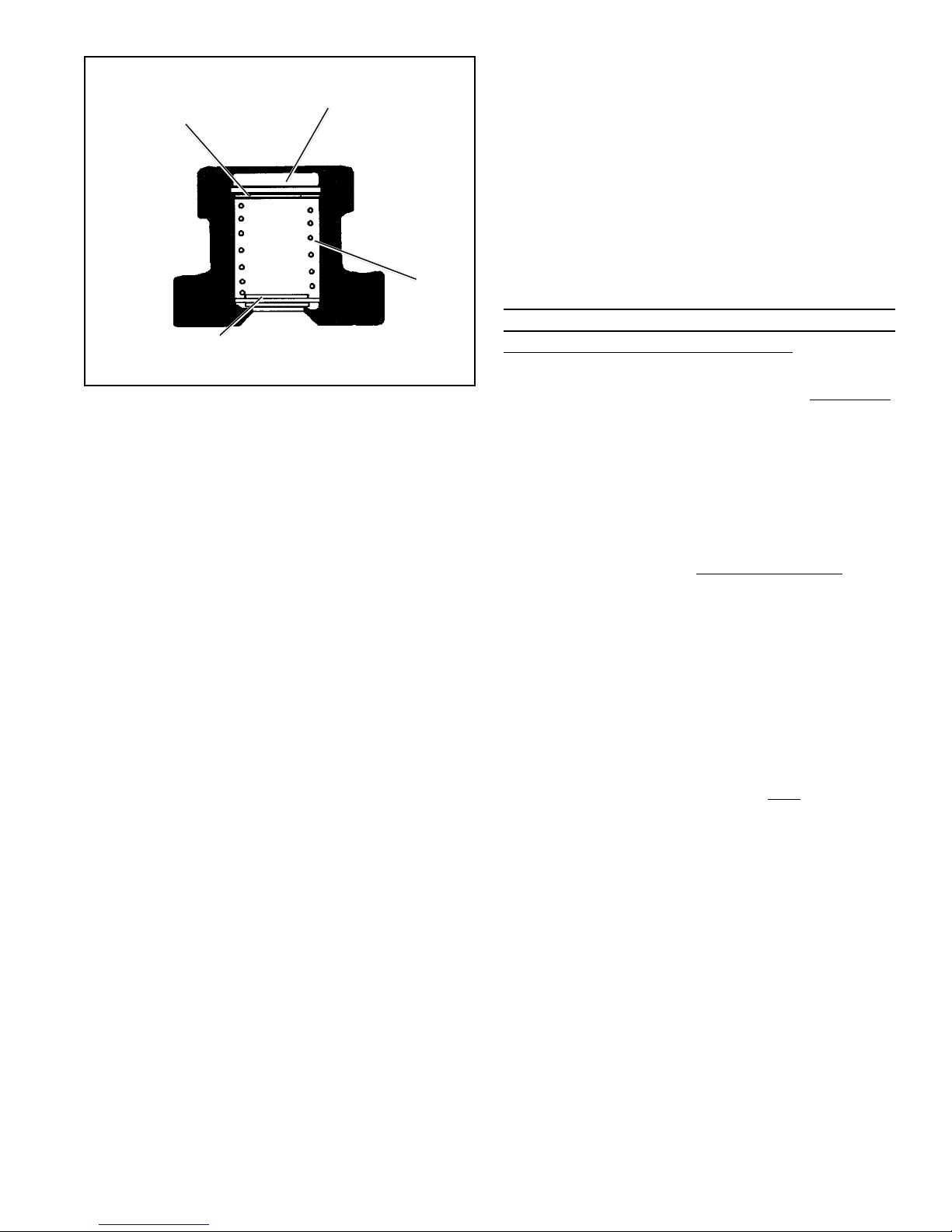
INLET-EXHAUST
VALVE (4)
WASHER
(2)
RETAINING
RING
(1)
INLET
EXHAUST
SPRING (3)
FIGURE 8 - LQ-3™FRONT AXLE RATIO VALVE INNER
PISTON ASSEMBLY
CLEANING AND INSPECTION
1. Wash all metal parts in mineral spirits and dry them.
2. Inspectall parts forexcessive wear ordeterioration.
3. Inspectthe valve seatfor nicksor burrs.
4. Check the spring for cracks or corrosion.
5. Replace all rubber parts and any part not found to be
serviceableduring inspection,usingonlygenuineBendix
replacementparts.
ASSEMBLY
Priortoreassembling the LQfrontaxleratio valve, lubricate
all o-rings, o-ring grooves, piston bores and metal moving
surfaceswithBendix siliconelubricantpiecenumber291126
(DowCorning650-M).
1. (LQ-3™valve — Figure 8) Place the inlet and exhaust
valve (4), valve spring (3), and washer (2) in the inner
piston.Install the retainingring(1) inthepiston, making
certain it is completely seated in its groove.
(LQ-4™valve — Figure 7) Place the inlet and exhaust
valve(10)andspring(9)intheinnerpiston(3).Thespring
must be carefully located under the shoulder in the
innerpiston.
2. Install the large (8) and small (7) diameter o-rings in
theirgrooves on theinner piston.
3. Install the o-ring (6) on the outer piston.
4. Insert the inner piston into the bore of the outer piston.
Note: See Figure 7 for proper inner and outer piston
configurationafterassembly.
5. Place the outer piston spring (5) in the valve body and
thehold-offspring(11) ifused.
6. Install the inner and outer piston assembly in the body
throughthe spring (seeFigure 7).