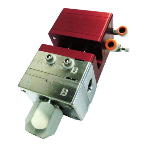
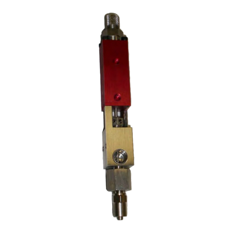
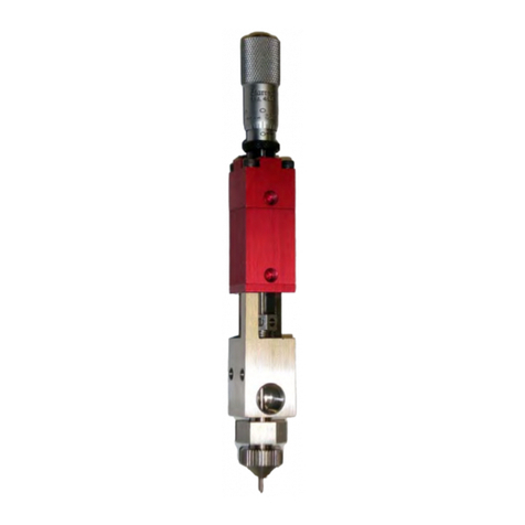
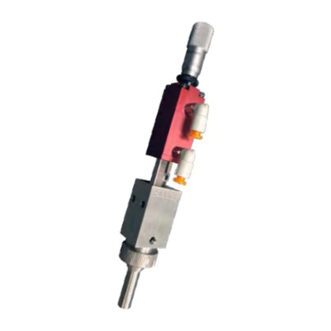
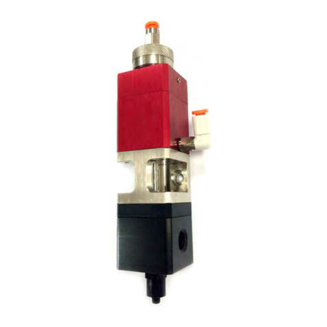
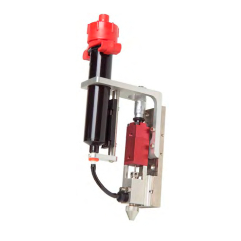
PVA SJ100 User manual

Precision Valve & Automation
One Mustang Drive
Cohoes, NY 12047
www.pva.net
SJ100
OWNER’S MANUAL
Revision C
WHERE
PRECISION
DRIVES
PRODUCTION

SJ100
PVA
Revision C(2019)
2 of 26
This document is based on information available at the time of its publication. While
efforts have been made to ensure the contents of this manual are accurate, the
information contained herein does not purport to cover all specific details or variations in
hardware, or to provide for every possible contingency in connection with installation,
operation, or maintenance. Features may be described herein which are not present in
all hardware and software systems. Precision Valve and Automation, Inc. assumes no
obligation of notice to holders of this document with respect to changes subsequently
made.
Precision Valve and Automation, Inc. makes no representation or warranty, expressed,
implied, or statutory with respect to, and assumes no responsibility for the accuracy,
completeness, sufficiency, or usefulness of the information contained herein. No
warranties of merchantability or fitness for purpose shall apply.
This document, including the information contained herein, is the property of
Precision Valve and Automation, Inc. and is considered confidential and
proprietary information. It is delivered on the express condition that it not be
used, disclosed, or reproduced, in whole or in part, for any reason without prior
written consent of Precision Valve and Automation, Inc.
Copyright © 2019
Precision Valve and Automation, Inc.
All Rights Reserved.

SJ100
PVA
Revision C(2019)
3 of 26
Table of Contents
Introduction ............................................................................................. 5
Document History ............................................................................................... 5
Safety .................................................................................................................. 6
Theory of Operation............................................................................................7
Personal Protective Equipment ..........................................................................7
Waste Disposal.................................................................................................... 7
Setup........................................................................................................ 8
Overview .............................................................................................................8
Operation................................................................................................. 9
Install Jet nozzle .................................................................................................. 9
Set the Valve Stroke..........................................................................................10
Prime the Valve.................................................................................................11
Set Fluid Pressure..............................................................................................11
Set Jet Pressure.................................................................................................11
Shutdown..........................................................................................................11
Cleaning Procedure...........................................................................................12
Maintenance .......................................................................................... 13
Flush the System ...............................................................................................13
How to Use the Valve with Portal ........................................................... 14
Setup Mode....................................................................................................... 15
Valve Positions ..................................................................................................17
Select a Recipe ..................................................................................................18
PathMaster .......................................................................................................19
Exploded View........................................................................................ 20
Item Numbers and Descriptions ............................................................... 20
Spare Parts ............................................................................................. 21
Technical Specifications.......................................................................... 22
Troubleshooting ..................................................................................... 23
Notes ..................................................................................................... 24

SJ100
PVA
Revision C(2019)
5 of 26
Introduction
Before you operate this system, read the operation and setup manual. This will help you
to become familiar with the product and ensure successful operation.
If any questions or problems arise, contact PVA’s Technical Support department.
PVA Contact Information
Main Office PVA
One Mustang Drive
Cohoes, NY 12047
Tel +1-518-371-2684
Fax +1-518-371-2688
Website http://www.pva.net
Email mailto: info@pva.net
Technical Support
Tel +1-844-734-0209
Document History
Revision
Revision Date
Reason for Changes
Revision A
November 2017
Initial Release
Revision B
August 2018
Dwell Time Corrected
Revision C
September 2019
Operating Air Pressure Updated
NOTE: All photographs and CAD model representations in this document are a
“general representation” of the system and its components. The actual
appearance of the system and its components can differ based upon customer
specific configuration.

SJ100
PVA
Revision C(2019)
6 of 26
Safety
Certain warning symbols are affixed to the machine and correspond to notations in this
manual. Before operating the system, identify these warning labels and read the
notices described below. Not all labels may be used on any specific system.
Always wear approved safety glasses when you operate or work
near the workcell.
Before you operate the system, read and understand the manuals
provided with the unit.
Never put hands or tools in areas with this symbol when the
machine is in operation. A dangerous condition may exist.
Read and understand the manuals provided with the unit before
any repairs or maintenance is done. Only a qualified individual
should do service.
Use caution when there are pressurized vessels. Find and repair any
leaks immediately. Always wear appropriate safety equipment
when you work with pressurized vessels or vessels that contain
chemicals.
Shear hazard from moving parts. Avoid contact
Pinch hazard from moving parts. Avoid contact.
Do not remove protective guarding.

SJ100
PVA
Revision C(2019)
7 of 26
Theory of Operation
The SJ100 valve is a non-contact dispense valve that applies small shots of fluid as
individual dots or in rapid succession. Only three components come in contact with
fluid: the fluid body, needle, and nozzle. With this design you can dispense at speeds up
to 140Hz. The SJ100 is designed to dispense coatings and other low viscosity materials
with very fine control.
Personal Protective Equipment
Operators must use eye protection because material contents are under pressure.
Always wear gloves when handling materials and solvents. Refer to MSDS sheets on the
material being dispensed for other precautions.
Waste Disposal
Dispose of all used parts and materials in accordance with local laws and regulations.

SJ100
PVA
Revision C(2019)
8 of 26
Setup
Before you operate the valve, know the valve components. Do the steps instructed
below for safe and correct operation.
Overview
Figure 1: Pump Components

SJ100
PVA
Revision C(2019)
9 of 26
Operation
NOTE: Refer to Section 6 for part reference numbers.
NOTE: Use only compatible solvents and materials or the seals and O-rings will
be damaged.
Install Jet nozzle
1. Use Portal to set the jet valve to “Open” or set the air pressure to 0 psi.
2. Turn the nozzle retaining cap counterclockwise to remove it.
Figure 2: Remove the Retaining Cap
3. Install the jetting nozzle.
NOTE: Make sure the nozzle O-ring is installed on nozzle.
Figure 3: Jetting Nozzle with O-ring
4. Push the nozzle retaining cap up over the jetting nozzle and turn is clockwise to
install the nozzle.

SJ100
PVA
Revision C(2019)
10 of 26
Figure 4: Install the Nozzle
5. Use Portal to set the jet valve to “Close” or increase the jet pressure.
Set the Valve Stroke
Do the procedure below to adjust the micrometer and set the valve stroke as necessary.
1. Turn the micrometer counterclockwise to increase the valve stroke.
2. Turn the micrometer clockwise to decrease the valve stroke.
NOTE: A larger valve stroke will result in larger dot sizes. Nominal valve stroke
is recommended at 0.01” but will be material and application dependent.
Figure 5: Micrometer

SJ100
PVA
Revision C(2019)
11 of 26
Prime the Valve
1. Connect the material syringe or the material line.
2. Make sure the material supply pressure is on or set to “SUP”.
3. Set the material supply pressure to 5 psi.
4. Examine the fluid reservoir, connections, and valve for leaks.
Set Fluid Pressure
1. Use Portal to set the valve to open.
2. Start at 5 psi and increase the fluid pressure until a steady stream or a
continuous flow of dots exits the nozzle. Fluids react differently, some may curl
up or pool at the nozzle outlet.
3. Once the necessary flow is achieved, use Portal to close the valve.
Set Jet Pressure
Jet pressure is the force that pushes the fluid out of the jet when it is dispensed. Too
little jet pressure, and the fluid will not leave the nozzle completely and accumulate on
the nozzle. Too much jet pressure, and the fluid will have satellites or splatter when it
hits the surface of the product. The jet pressure must be set between 45-65 psi to work
correctly.
1. Set the operating air pressure at 45 psi to start.
2. Dispense the material and examine the nozzle and surface that was dispensed
on for buildup, splatter, or satellites.
3. Adjust the jet pressure until the results are correct.
NOTE: The maximum jet pressure is 65 psi.
Shutdown
•Release the pressure in the system, refer to the workcell manual for additional
information.

SJ100
PVA
Revision C(2019)
12 of 26
Cleaning Procedure
1. Reduce the material pressure to 0 psi.
2. Reduce the jet pressure to 0 psi.
3. Remove the material fitting.
4. Remove the nozzle retainer.
5. Remove the nozzle.
6. Remove the two screws securing fluid body.
7. Remove the fluid body.
8. Clean the end of the jetting needle with a recommended solvent.
9. Clean the removed wetted components with a recommended solvent.
10. Examine the needle and the O-rings for damage.
11. Replace any damaged components.
Figure 6: Disassemble the Valve

SJ100
PVA
Revision C(2019)
13 of 26
Maintenance
Interval
Action
Daily
•Examine the material outlets for contamination and cured
material.
Weekly
•Examine the material containers or cartridges for signs of cured
or dried material.
Shutdown
•Flush or clean the system.
•Clean or replace the nozzle plate, diaphragm, and feed tube.
Flush the System
1. Supply the valve with the recommended solvent.
2. Increase the material pressure.
3. Make sure the solvent is dispensed in a purge cup, and dispense 250 drops. Do
this 5-6 times until the solvent is clear.
4. Turn off the material pressure.
5. Remove the solvent supply.
6. Remove and clean the jetting nozzle and the fluid body.
7. Clean the jetting needle.
8. Reassemble the valve.

SJ100
PVA
Revision C(2019)
14 of 26
How to Use the Valve with Portal
If your valve is on a workcell that has PVA Portal, use the screens that follow to operate
the valve. Refer to the Portal manual for more information.
NOTE: Titles for the valve specific settings may say Jetter, JDX or SJ100. In
this manual they will be shown as JDX.
NOTE: Screens may differ based on customer specific configuration.
The gauges that are related to the jet valve can be seen in any mode. Select the Gauges
tab in the Systems tab section of the screen, the (#1) Pressure, Material Syringe
pressure and Vacuum Pressure gauges are related to the jet valve.
Figure 7: Example Jetter Gauges

SJ100
PVA
Revision C(2019)
15 of 26
Setup Mode
The settings that are used in Auto Cycle can be changed in Setup mode, as shown below.
1. Select Setup mode.
2. Select the Setup Tree tab.
Figure 8: Setup Tree Tab
3. Select the + symbol next to a Parameter to expand the setup tree. Expanded
options are in color.
Figure 9: Clean Settings

SJ100
PVA
Revision C(2019)
16 of 26
Figure 10: Pressure Settings
4. Double click on any parameter to open an edit window. Select the button to
enable or disable an option. To adjust a value, use the arrows or type the value
in the value box shown.
5. Select “Done” to keep the change or “Cancel” to exit without making any
changes.
NOTE: Most settings for the Jet Valve are set with the PVA Jet Valve
Controller.

SJ100
PVA
Revision C(2019)
17 of 26
Valve Positions
1. Select the Positions tab from Setup mode.
2. Select the necessary position from the menu.
3. Select the Teach “Go” button.
4. A message will be shown on the screen and the teach pendant Teach light will
come on. Use the teach pendant to move the valve to the necessary position,
and select the “Teach” button. The location for the selected position will be set.
Figure 11: Clean Positions
5. Select the Home “Go” button to home the workcell.

SJ100
PVA
Revision C(2019)
18 of 26
Select a Recipe
To operate the valve in Manual mode, do the steps below.
1. Select Manual mode.
2. Select the JDX tab.
3. Use the up and down arrows to increase or decrease the value for the necessary
valve parameter (Refill, Dwell, Cycles).
4. Select the JDX Hardware “Setup” button to set the valve to open for
disassembly or service. The screen will show a message about the valve.
Figure 12: Manual Mode, Jetter Tab
NOTE: These settings and changes apply only in Manual mode, unless you
select the Apply to Auto “Go” button.
5. The parameters shown will be used when the “Purge” button on the teach
pendant is used, or when the valve is operated in the Run tab.
6. Select Apply to Auto “Go” to set all the values and settings shown on this page
for Auto Cycle for the selected program.
7. Select the Clean JDX “Go” button to move the valve to the vacuum cup.

SJ100
PVA
Revision C(2019)
19 of 26
PathMaster
Below is an example screen with a path template for the jet valve. Refer to the
PathMaster manual for more information on how to create path programs.
Figure 13: PathMaster With Path Example

SJ100
PVA
Revision C(2019)
20 of 26
Exploded View
Figure 14: Exploded View
Item Numbers and Descriptions
Item
Description
Part Number
QTY
1.
Air Body
614-9798-1
1
2.
O-ring seal
VLV-004K
1
3.
Fluid body
614-8127-2
1
4.
Fluid body screw
SHCS M3x0.5 X 12 (12NHX)
2
5.
Material fitting assembly
Fitting- CFLT-1032M-WN
Elbow- CMFMER-WN
Luer lock ring- CLFSR-WN
1
1
1
6.
Nozzle O-ring
Material dependent
1
7.
Nozzle
Material dependent
1
8.
Nozzle retainer
614-9801-1
1
Table of contents
Other PVA Control Unit manuals
Popular Control Unit manuals by other brands

Telit Wireless Solutions
Telit Wireless Solutions BlueMod+S42/AI Hardware user's guide

Simon
Simon SMD Information & Instructions

Nordson
Nordson Liquidyn P-Jet CT operating manual

Opera
Opera RELIEVE Overlay Mattress System Instruction manual and specifications

FIBARO
FIBARO Home Center 2 manual

Douglas Dynamics
Douglas Dynamics 29049 Parts List and Installation Instructions

PPM
PPM ViaLiteHD HRD-1-L1-0R-01 user guide

RFL Electronics
RFL Electronics GARD 8000 instruction manual

Trinamic
Trinamic TMCM-1076 Hardware manual

Feig Electronic
Feig Electronic OBID i-scan D ISC.MU02.02 Installation

T&S
T&S B-0108-H Installation and maintenance instructions

oventrop
oventrop DynaTemp RBG-C F installation instructions