Kieback&Peter FCS User manual

Technical data sheet 1.15-90.002-01-en
Device description FCS Radio Control Transmitting Module
Radio Control Transmitting Module FCS
Pluggable transmitting module for equipping the
Multi Radio Controller MFC and wirelessly driving
field devices.
Contents Notes on the device description Page 2
Safety Instructions Page 2
Qualified specialists Page 2
Application Page 3
Models Page 3
Technical data Page 3
Assembly Page 4
Addressing Page 6
Initial operation Page 7
Kieback & Peter GmbH & Co KG
Tempelhofer Weg 50
D-12347 Berlin
Telephone 030 / 600 95-0
Telefax 030 / 600 95 164
http://www.kieback-peter.de
Issue date: 04/29/2004 Contents subject to change

Technical data sheet 1.15-90.002-01-en
FCS Radio Control Transmitting Module Device description
Notes on the device description
The description contains instructions on using and assembling the Radio Control Transmitting Module FCS.
In case of questions which cannot be clarified with this device description, please refer to the supplier or
manufacturer for further information.
The indicated installation instructions/regulations are valid in the Federal Republic of Germany.
When utilising the devices in other countries, the builder or operator of the plant is responsible for the observation
of the respective national regulations.
The operating staff shall be trained according to the descriptions of the technical data sheet.
Safety Instructions
It must be guaranteed that in non-utilisation periods (e.g., delivery or storage) the address code of the Radio
Control Transmitting Module FCS is set to “000”.
The respective worker’s protection rules, regulations for prevention of accidents and VDE rules shall be observed
Any work concerning the installation or initial operation of the actuating device or valve shall be exclusively
carried out by qualified specialists, see paragraph “Qualified specialists”.
Every person utilising the devices shall have read and understood the descriptions in the technical data sheet.
Meaning of the symbols in the technical data sheet:
General warning, strictly observe this notice
Warning
Further notice to observe
Note
Warning means danger of bodily injuries or material damage in case of non-observance.
Note indicates an information which is particularly stressed.
Qualified specialists
Qualified specialists for the purposes set out in this technical data sheet are persons who are familiar with the described
devices and possess a qualification for their respective occupation.
These are for instance:
• Authorisation to connect the devices according to the VDE rules and local regulations, as well as the
authorisation to switch the devices on and off taking the in-house regulations into account.
• Knowledge of the regulations for prevention of accidents.
• Knowledge of the utilisation of the devices within the plant system.
etc.
Page 2 / 8

Technical data sheet 1.15-90.002-01-en
Device description FCS Radio Control Transmitting Module
Application
Radio Control Transmitting Modules FCS are the interfaces in the signal chain
between line and wireless transmission path.
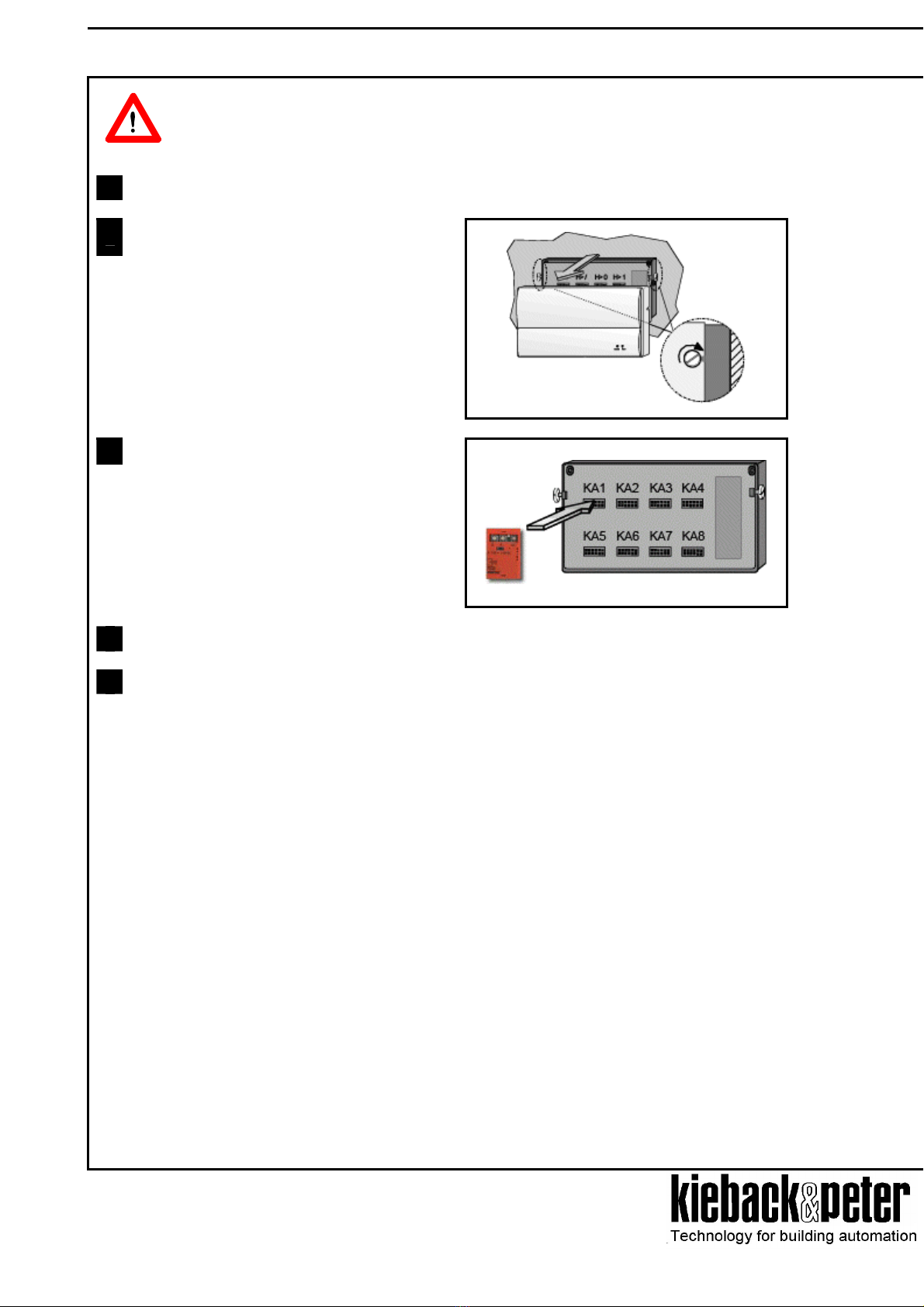
FCS is prepared ready-to-plug for reception in the plug positions KA1..KA8 of the
MFC. In combination, the FCS and MFC establish the function unit of a receiving
radio converter for a signal chain
FCS operates unidirectionally, i.e. field devices (e.g. radio controlled actuating
drives MD100Y) are wirelessly driven through periodically sent radio telegrams.
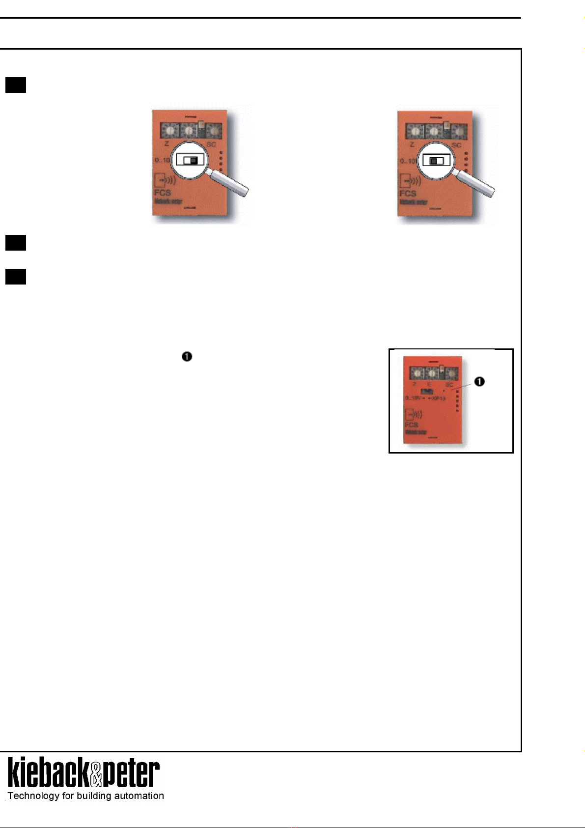
Optionally, 0..10 V radio telegrams or KP10 radio telegrams can be transmitted.
FCS
Models
FCS Pluggable transmitting module for reception in the plug positions KA1..KA8 of an MFC.
Compact module to wirelessly drive field devices incl. configuration switch and status display.
Optionally, 0..10 V radio telegram or KP10 radio telegram.
FCS10 like FCS, but in packaging units of 10 pcs.
Technical data
Mains 12 V DC ±10% (power supply via plug connection to MFC)
Power draw Transmission operation 0.5 VA
Transmission pause 0.3 VA
Transmitter frequency 868.35 MHz
Transmitting power < 10 mW
Range 10..50 m inside the building (depending on built volumes)
Duty Cycle < 0.1 %
Transmitting interval 23 s
Radio telegram optionally 0..10 V DC/ KP10
Signal range -50..+150°C (2.73 V at 0°C, TK 10mV/K)
Display 1 multi-coloured LED to display
- Transmission operation (green)
- Transmission pause (off)
- Error (blinking red/ permanent light)
Ambient temperature 0..50 °C
Assembly ready to plug in MFC reception positions KA1..KA8
Dimensions Width x height x depth = 30 x 40 x 20 mm
Weight 0.01 kg
Page 3 / 8

Technical data sheet 1.15-90.002-01-en
FCS Radio Control Transmitting Module Device description
Assembly
General installation notes
Devices communicating via radio can not always be assembled at arbitrary locations, as wireless data
transmission is more or less strongly influenced by the constructional and spatial conditions.
Prior to installation and assembly, therefore, the building volumes must be analysed and a series of
measurements must be carried out to determine the specific ranges inside the building. A Kieback&Peter
measurement set is available for this purpose.
To establish an operational and functionally secure communication path, the following aspects must be taken into
account prior to and during planning:
• Natural and constructional influences limit the transmission ranges that can be realised. Building materials and
screening elements (e.g., installation shafts, fire doors, switching cabinet doors, etc.) must be taken into
account already during the planning phase.
High humidity increases the natural signal attenuation.
Warning
Recommendation: Plan the radio lines horizontally, on one level with max. 30 m distance
between transmitting and receiving components.
Note
• Observe the minimum distances to potential sources of interference
- min. 0.5 m to high-frequency interference sources (e.g., microwaves, transformers, computers...)
- min. 3 m to transmitters of other function systems (e.g., wireless telephones, headphones...)
- min 0.1 m to metal and door frames
correct false
• Do not choose the installation site in the radio shadow of screening building parts/volumes →no direct
reception possible.
• In the fringe range of reliability, slightly change the position of transmitter/receiver if required (to reduce
heterodyne radio waves).
Page 4 / 8

Technical data sheet 1.15-90.002-01-en
Device description FCS Radio Control Transmitting Module
The assembly of the Radio Control Transmitting Modules FCS in the MFC may only be carried out by
qualified specialists at an MFC switched voltage-free!
Warning
1 Before starting assembly work, the MFC must be safely disconnected!
2 Take off the housing hood of the MFC after
loosening the two base screws at the side.
3
Plug the FCS into the desired reception socket
KA1..KA8.
4 Carry out initial operation (see paragraph “Initial operation”).
5 Place the MFC housing hood back on and secure it with the two base screws.
Page 5 / 8

Technical data sheet 1.15-90.002-01-en
FCS Radio Control Transmitting Module Device description
Addressing
The Radio Control Transmitting Module FCS has 3
rotary switches to set the system code and the device
address.
By means of the 3-digit address code, radio paths with
theoretically up to 999 participants can be established.
Note
The set address code at the FCS must match that of the corresponding receiver (e.g. MD100Y) so
that an unambiguous allocation between transmitter and receiver of the radio path is determined.
On principle, a Radio Control Transmitting Module FCS can be effective on more than one wirelessly driven field
device.
Setting the address code
Device address System code
The 3-digit address code consists of a 1-digit system code and a 2-digit
device address
Example for address 123:
System code 1
Device address 23
− Via the system code, participants of a radio network can be grouped according to different criteria, e.g. floor.
− The device address differentiates the network participants within one system code.
Page 6 / 8

Technical data sheet 1.15-90.002-01-en
Device description FCS Radio Control Transmitting Module
Initial operation
LED displays
LED Function
off sleep mode; module in transmission pause
green short
blinking
passive operating mode
green long
blinking (LED on
approx. 1 s)
transmission mode; module transmitting a radio telegram
red blinking error mode: faulty connection recognition
− line signal ring 0..10 V not closed
− KP10 signal in an impermissible range (<2.2 V/>4.4 V)
− selected signal type does not correspond with the existing line input signal at
the MFC terminal
The error blinking of the LED continues as long as the state causing
the error remains
Warning
red permanent
light
address setting “000”
Description of initial operation
1. Before switching on the mains, the correct assembly and the electric connection is to be checked.
Initial operation may be carried through by qualified expert personnel only!
Note
Specific settings and functions of the FCS are described in this device description. In addition to
these notes, the device descriptions MFC, MD100Y, F/MD, MFA, FCE must be observed.
1 Set the address code
The same address code must be set at the assigned receiving modules as well.
Warning The device is delivered with the setting “000”.
Page 7 / 8

Technical data sheet 1.15-90.002-01-en
FCS Radio Control Transmitting Module Device description
2 Select the signal type via the operating mode switch
- Sensor mode KP10
- Actuation mode 0..10 V
3
Compare address code with field devices to be driven, i.e. the FCS and the assigned radio communicating
field device must have the same address code.
4 Teaching the radio controlled actuating drives
Actuating drive MD100Y
• Set the actuating drive to learning mode (see device description MD100Y);
if applicable, set further actuating drives MD100Y to learning mode if they are driven by the same
transmitting module.
Press the covered learning button at the FCS with the appropriate contrivance
→The address code is conveyed via a radio telegram to all ready-to-receive
actuating drives MD100Y in learning mode.
→Synchronisation of the transmission interval of radio telegrams of all ready-
to-receive actuating drives MD100Y in learning mode.
→MD100Y acknowledges the correct reception of the radio telegram via a
series of tones.
Actuating drive MD200Y/MD210Y with radio module F/MD
• Set the address code of the Transmitting Module FCS at the bidirectional Radio Module F/MD;
If required, repeat the setting with further actuating drives, in case these are driven by the same
transmitting module (see device description F/MD).
• Set 0..10 V radio telegram (drive mode 0..10 V) at the F/MD (see device description F/MD).
• The learning of the Transmitting Module FCS and the assigned driven field devices is now carried out
automatically with the next regular radio telegram. A special learning mode is not required, as the
receiver of the Radio Module F/MD is always active and ready to receive.
Page 8 / 8
Table of contents
Popular Transmitter manuals by other brands

Wilkerson Instrument
Wilkerson Instrument DR4302 Series instructions

Nivus
Nivus NivuFlow Mobile 600 instruction manual

IFM Electronic
IFM Electronic Efector 600 TD Series operating instructions

DMP Electronics
DMP Electronics 1103 Series installation guide

BuildCircuit
BuildCircuit BC-0012 quick guide

AAREFF
AAREFF 100MWPLLSB manual

Linear
Linear Multi-Code 1051 user manual

NIVELCO
NIVELCO NIVOPRESS DT 1 Series Installation and programming manual

Extron electronics
Extron electronics USB Extender Plus Series Setup guide

Ritron
Ritron RQA-152M Installation and operating instruction manual

DAPAudio
DAPAudio ER-16B manual

tau
tau T-4RP OPERATION AND PROGRAMMING