Metal Samples Company CorrTran MV MS2900L User manual

MS2900L Transmitter
Operator’s
Manual
Metal Samples Company
ADivision of Alabama Specialty Products, Inc.
152 Metal Samples Rd., Munford, AL 36268 Phone: (256) 358-4202 Fax: (256) 358-4515

CorrTran MV Corrosion Monitor
1
Contents
1 SAFETY INSTRUCTIONS / DISCLAIMER ................................................................... 2
1.1 Designated use .................................................................................................... 2
1.2 Installation, commissioning, and operation .......................................................... 2
1.3 Operational safety ................................................................................................ 2
1.4 Maintenance safety ............................................................................................... 2
1.5 Notes on safety conventions and symbols ........................................................... 3
1.6 Disclaimer ............................................................................................................. 3
2 IDENTIFICATION........................................................................................................... 3
2.1 Device designation ............................................................................................... 3
2.2 Contents of delivery .............................................................................................. 5
2.3 Incoming acceptance, transport, storage ............................................................. 5
2.4 Certicates and approvals .................................................................................... 5
2.5 Registered trademarks ......................................................................................... 5
2.6 Patents ................................................................................................................. 5
3 INSTALLATION AND MOUNTING ............................................................................... 6
3.1 Dimensions............................................................................................................ 6
3.2 Probe specications ............................................................................................. 9
3.3 Mounting safety procedures and hints ............................................................... 15
3.4 Installation instructions ....................................................................................... 19
4 WIRING ....................................................................................................................... 24
4.1 Quick wiring guide .............................................................................................. 24
4.2 HART introduction .............................................................................................. 25
4.3 Wiring with HART ............................................................................................... 25
4.4 Post-installation check ........................................................................................ 26
5 CONFIGURATION AND COMMISSIONING .............................................................. 27
5.1 PACTware introduction ....................................................................................... 27
5.2 Establishing communication with PACTware ..................................................... 27
5.3 CorrTran MV online variables and parameters ................................................... 31
5.4 CorrTran MV test probe: CMP-TESTER ............................................................. 40
6 REPLACEMENT PARTS AND ACCESSORIES ........................................................ 41
6.1 CorrTran MV parts .............................................................................................. 41
6.2 HART accessories .............................................................................................. 44
6.3 Surge protection and IS barriers ........................................................................ 44
6.4 Additional accessories ........................................................................................ 45
7 SYSTEM SPECS ......................................................................................................... 45
8 TROUBLESHOOTING ................................................................................................ 49
9 MEASURING PRINCIPLE ........................................................................................... 51
10 APPENDIX A................................................................................................................ 53
11 APPENDIX B: CorrTran EC Startup........................................................................... 56
11.1 CorrTran MV/EC Evaluation Tool ........................................................................ 56
11.2 Hints on Extending Battery Life ........................................................................... 59
12 Notes ........................................................................................................................... 60
CorrTran MV Corrosion Monitor
2
1 SAFETY INSTRUCTIONS / DISCLAIMER
1.1 Designated use
The CorrTran MV is a compact, 4-20 mA corrosion transmitter used to detect general
corrosion, localized corrosion, and conductance in a wide range of industries. The
transmitter measures the corrosion rate and pitting factor, giving the readout in mil/year or
a 0-1 pitting factor, respectively. It also provides a conductance measurement. The readings
are taken in real time and are updated every 21 minutes.
1.2 Installation, commissioning, and operation
CorrTran MV is designed to operate safely in accordance with relevant technical and
safety standards. If installed incorrectly or used for applications for which it is not intended,
application-related dangers may arise. For this reason, the instrument must be installed,
connected, operated, and maintained according to the instructions in this manual by
appropriately trained personnel. This manual must be read, understood, and the instructions
must be followed. Modications and repairs to the device are permissible only when they
are expressly approved in this manual.
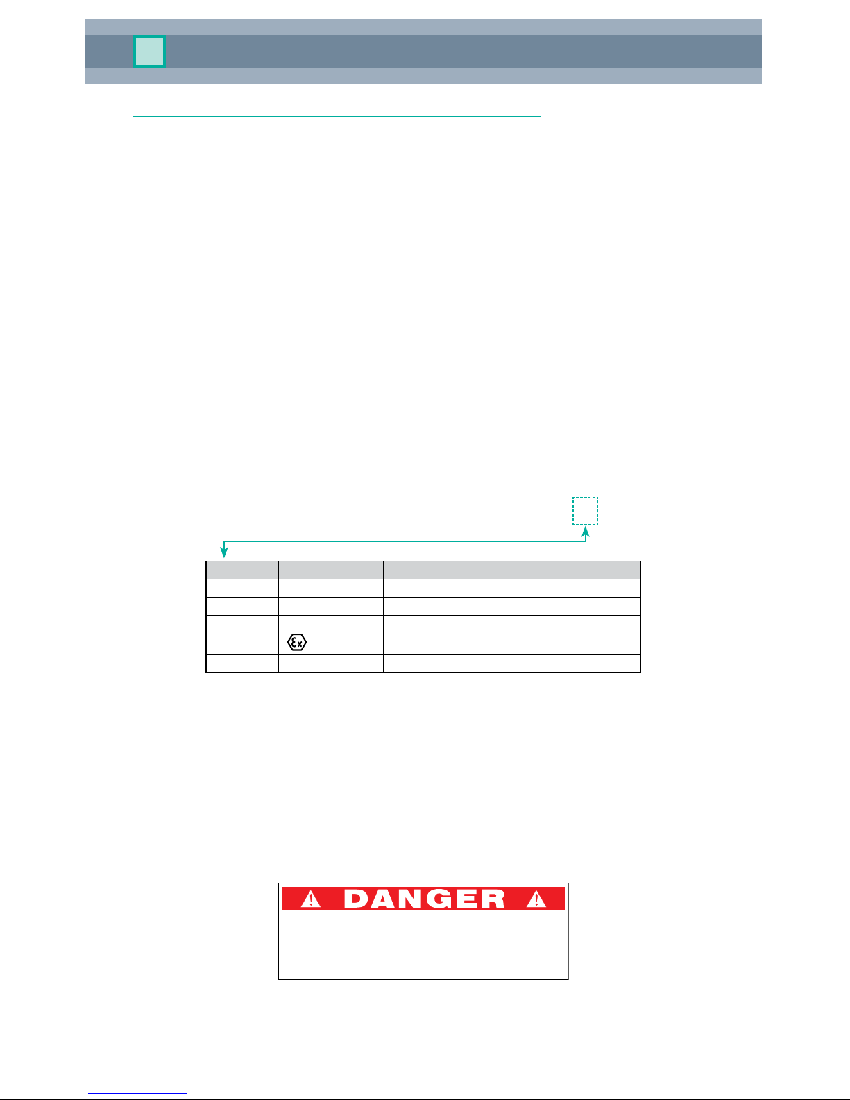
1.3 Operational safety
Measurement systems used in a hazardous (classied) area must comply with all existing
national standards. CorrTran MV can be supplied with the certicates listed in Table 1. All
technical personnel must be sufficiently trained. All measurement and safety regulations
that apply to the measuring points must be observed.
CorrTran MV CMC M - _ _ _ _ _ _ _ _ _ - _ _ - _ _ _ _ _ - _ _ - _ _ _
Code Certicate Protection
GP N/A General Purpose
D2 cCSAus NI: Cl. I, II, III; Div. 2: Groups A…G
IS cCSAus IS: Cl. I, II, III; Div. 1, 2; Groups A…G
II 1G EEx ia IIC T4
EX cCSAus EX: Cl. I; Div. 1,2; Groups A…D
Table 1. Certicates for Application in Hazardous Areas
General-purpose versions of CorrTran MV shall only be used to detect corrosion in tanks
and pipes that are non-hazardous (non-explosive). Failure to comply with this specication
will create a potentially hazardous situation.
1.4 Maintenance safety
The transmitter must be mounted with the safety warning label visible at all times to any
employee or other person called upon to replace the electrodes or otherwise service the
transmitter. The label is on every safety bracket with adjustable probes. Please see section
6.4 for ordering instructions.
DO NOT REMOVE THIS DEVICE UNLESS PIPE OR VESSEL
HAS FIRST BEEN DEPRESSURIZED AND PURGED OF
ANY HAZARDOUS SUBSTANCES. DEATH OR INJURY MAY
RESULT IF SAFETY PROCEDURES ARE NOT OBSERVED.
CorrTran MV Corrosion Monitor
3
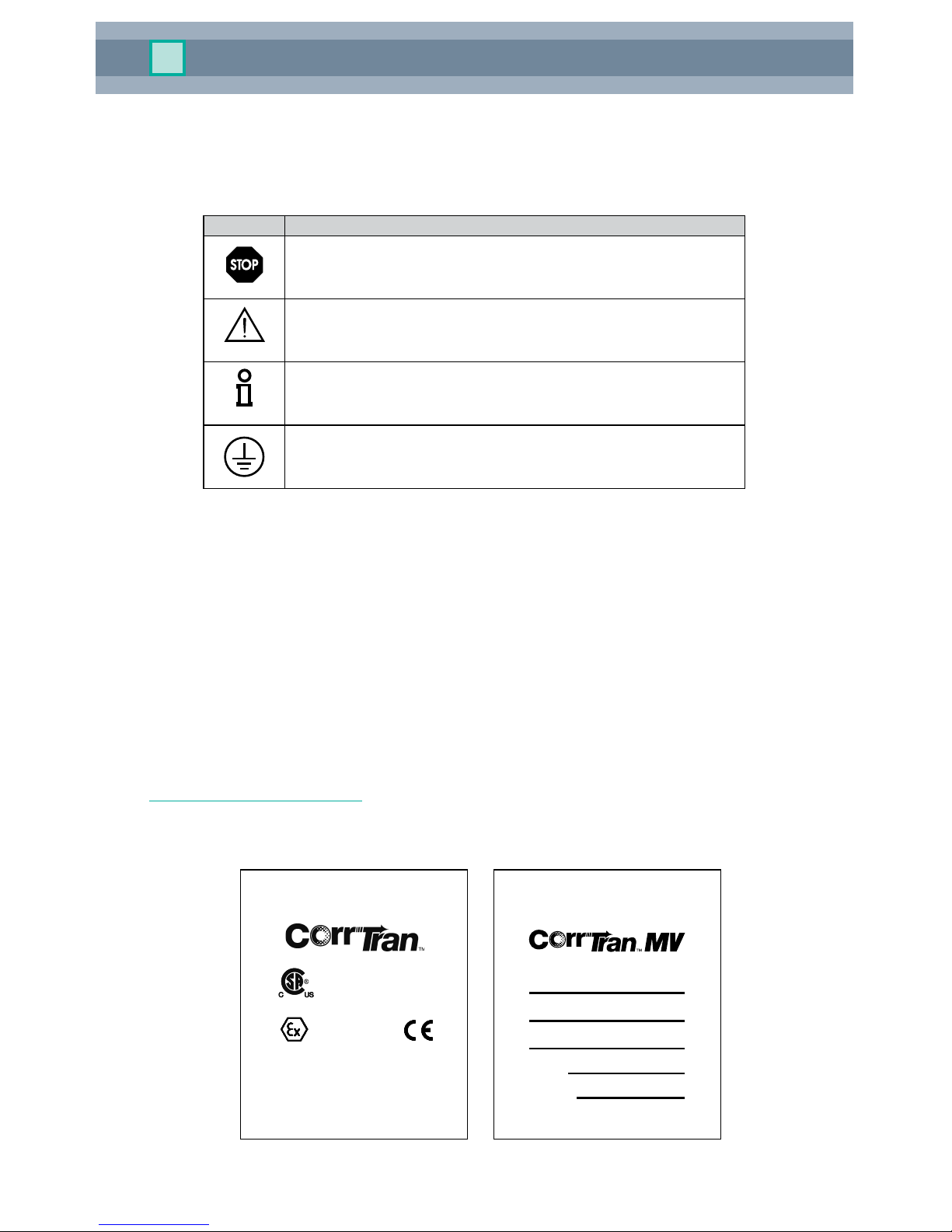
1.5 Notes on safety conventions and symbols
The following conventions are used to highlight safety-relevant or alternate operating
procedures in this manual and are shown in the margin where appropriate.
Safety conventions
Symbol Meaning
Warning
A warning highlights actions or procedures which, if not performed
correctly, will lead to personal injury, a safety hazard, or destruction of
the instrument.
Attention
A caution highlights actions or procedures that, if not performed
correctly, may lead to personal injury or incorrect functioning of the
instrument.
Note
A note highlights actions or procedures that, if not performed correctly,
may indirectly affect operation or may lead to an instrument response
which is not planned.
A terminal symbol indicates that a protective grounding (earth)
terminal must be connected to earth ground prior to making any other
connection to the equipment.
1.6 Disclaimer
Metal Samples has no power, nor does it undertake to police or enforce, compliance with
the contents of this manual or observance of the safety precautions set forth herein. Metal
Samples does not certify, test, or inspect the installations of CorrTran MV for safety or other
purposes. Metal Samples disclaims liability for any personal injury, property, or other
damages of any nature whatsoever, whether special, indirect, consequential, or
compensatory, directly or indirectly resulting from the publication, use of, or reliance upon
this manual. Metal Samples makes no guaranty or warranty, express or implied, as to the
accuracy or completeness of any information published in this manual, and disclaims and
makes no warranty that the information in this manual will fulfill any particular purposes or
needs. Metal Samples' only warranty is set forth in the written Limited Warranty specifically
provided by Metal Samples in connection with the purchase of the CorrTran MV.
2 IDENTIFICATION
2.1 Device designation
2.1.1 Nameplates
black
Twinsburg
CONFIDENTIAL acc. to ISO 16016 Only valid as long as released in EDM or with a valid production documentation!
PRINT PLATE for
CorrTran DIV (I.S.)
respons.
approved
norm
US.JMB
date: 2005-Nov-04
sheet 1 of 2
110-2417A
plate number print laser sticker
scale: 1:1
Dieses Dokument enthält sicherheitsrelevante Angaben. Es darf nicht ohne Absprache mit dem Normenfachmann geändert werden!
This document contains safety-relevant information. It must not be altered without the authorization of the norm expert!
US.AAS
US.CPR
110-2417 / A
Input = 9 - 30 Vdc Output = 4 - 20mA HART
a
Cl. I, Div. 1, Gr. A,B,C,D; T4
Cl. II, Div. 1, Gr. E,F,G; Cl. III
WARNING - SUBSTITUTION OF COMPONENTS
MAY IMPAIR INTRINSIC SAFETY
INTRINSICALLY SAFE WHEN
INSTALLED PER DRAWING 116-0275
-40°C<T <70°C
CSA Type 4X IP67
Exia
II 1G EEx ia IIC T4
LCIE 05ATEX6097X
Twinsburg, OH USA (330) 425-3555
2005-Nov-04
110-2417 / A
SCALE = 2X
Input = 9 - 30 Vdc Output = 4 - 20mA HART
a
Cl. I, Div. 1, Gr. A,B,C,D; T4
Cl. II, Div. 1, Gr. E,F,G; Cl. III
WARNING - SUBSTITUTION OF COMPONENTS
MAY IMPAIR INTRINSIC SAFETY
INTRINSICALLY SAFE WHEN
INSTALLED PER DRAWING 116-0275
-40°C<T <70°C
CSA Type 4X IP67
Exia
II 1G EEx ia IIC T4
LCIE 05ATEX6097X
110-2417A 110-2417A->Released EDM checkout 2009-JAN-20
black
Twinsburg
CONFIDENTIAL acc. to ISO 16016 Only valid as long as released in EDM or with a valid production documentation!
PRINT PLATE for
CorrTran MODEL
respons.
approved
norm
US.JMB
date: 2007-Sep-28
sheet 1 of 2
110-2388D
plate number print laser sticker
scale: 1:1
Dieses Dokument enthält sicherheitsrelevante Angaben. Es darf nicht ohne Absprache mit dem Normenfachmann geändert werden!
This document contains safety-relevant information. It must not be altered without the authorization of the norm expert!
US.RHW
110-2388 U D
SCALE = 2X
Made in U.S.A.
Serial No.
Twinsburg, OH USA / www.pepperl-fuc hs.com
Part No.
Patents: 7,239,156 7,245,132
7,265,559 7,282,928
2007-Sep-28
110-2388 U D
Made in U.S.A.
Serial No.
Part No.
Patents: 7,239,156 7,245,132
7,265,559 7,282,928
110-2388D 110-2388D->Released EDM checkout 2009-JAN-20

CorrTran MV Corrosion Monitor
4
2.1.2 Key to model number
*Probe Mounting Guide and Electrode Material Guide can be found in the Appendix.
C M C M - - - A 2 I H - -
Insertion Length (fixed probes only)
in inches, 5" … 28", in 0.2" increments
050 5.0"
052 5.2"
…
278 27.8"
280 28.0"
in mm, 130mm … 710mm, in 5mm increments
130 130mm
135 135mm
…
705 705mm
710 710mm
Certificates
D2 cCSAus, NI, Cl. I,II,III; Div. 2, Group A-D
Ex cCSAus, EX, Cl. 1; Div. 1,2; Group A-D
GP gneral purpose
IS cCSAus, IS, Cl. I, II, III; Div. 1, 2; Group A-D
II 1G EEx ia IIC T4
Transmitter Mounting
1 direct mount
2 remote mount with 1.8m (6') cable
3 remote mount with 3.6m (12') cable
4 special mount
5 remote mount with 1.8m (6') cable with retrievable probe adapter
6 remote mount with 3.6m (12') cable with retrievable probe adapter
Electrical Output
IH 4-20 mA, HART
Housing
A2 aluminum housing, Nema 4x, 3/4" NPT
Electrode Material
0A… see electrode material guide
Probe Length
050* 5", 3/4" NPT
080 8", 3/4" NPT
110*
11", 3/4" NPT
120 12", 3/4" NPT or Flange
180 18", 3/4" NPT or Flange
240 24", 1" NPT, 3/4" NPT, or Flange
300 30", 1" NPT, 3/4" NPT, or Flange
127* 127 mm, 3/4" NPT
204 204 mm, 3/4" NPT
280* 280 mm, 3/4" NPT
305 305 mm, 3/4" NPT or Flange
457 457 mm, 3/4" NPT or Flange
610 610 mm, 1" NPT, 3/4" NPT, or Flange
762 762 mm, 1" NPT, 3/4" NPT, or Flange
ADP Retrievable Probe Electrical Adaptor
*epoxy probe only
Probe Mounting
See probe mounting guide
Measurement Unit, Probe Material
CB inches, 1.4435, 316L
CC inches, hastelloy C
CF inches, epoxy glass
DB mm, 1.4435, 316L
DC mm, hastelloy C
DF mm, epoxy glass
HF
HF applications, no glass seal
CS Special, consult factory
Process Connection
A31 1", flange ANSI B 16.5, 150 lbs
A32 1", flange ANSI B 16.5, 300 lbs
A61 2", flange ANSI B 16.5, 150 lbs
A62 2", flange ANSI B 16.5, 300 lbs
F61 DN40 PN6 Form B Flange
F65 DN40 PN40 Form B Flange
N21 3/4" NPT, ANSI B 1.20.1, 1.4435/316L
N2P
3/4" NPT, ANSI B 1.20.1, adj. thread, nylon
N31 1" NPT
U31 UNS 1-14, 1" left handed thread
XXX Special Version
*Consult factory for other available options
Corrosion Type
M Multivariable

CorrTran MV Corrosion Monitor
5
2.2 Contents of delivery
It is essential to follow the instructions concerning the unpacking, transport,
and storage of this instrument given in section 2.3, “Incoming acceptance,
transport, storage.”
The contents of delivery consist of:
• Assembledinstrument
• Stainlesssteelprobe
• 3-electrodeelements(ngertypesattachedlooselyinbox)
• Cable(remotemountversiononly)
• Accessories(ifanyareordered)
• Instructionmanual(thisdocument)
2.3 Incoming acceptance, transport, storage
2.3.1 Incoming acceptance
Check the packing and contents for any signs of damage. Check the shipment to ensure
that all parts have been included and to verify that the shipment matches your order.
All probes are shipped with the insulating gaskets installed. Upon removing the
protective cap, ensure that the O-rings are not loose. The O-rings are made of
Viton®(standard) or Kalrez (on request). If they are not installed, the probe will
not operate properly. Please refer to Figure 17 on page 20.
2.3.2 Transport
Protect the transmitter electrodes from damage. Do not attempt to carry the transmitter by
its electrodes.
2.3.3 Storage
Always pack the instrument for storage or transport to protect it against impact. The original
packing material provides the optimum protection for the device. The permissible storage
temperature is -40 °F to +176 °F (-40 °C to +80 °C).
2.4 Certicates and approvals
The CorrTran MV is designed to meet relevant safety requirements. It has been fully tested
to ensure that it is in safe operating condition. The instrument complies with the applicable
regulations in accordance with known standards.
2.5 Registered trademarks
HART®
Registered trademark of HART Communication Foundation, Austin, USA
Viton®
Registered trademark of the company E.I. Du Pont de Nemours & Co., Wilmington, USA
Teon®
Registered trademark of the company E.I. Du Pont de Nemours & Co., Wilmington, USA
2.6 Patents
This instrument is protected by one or more patents registered in the US Patent Office.
Warning
Attention
CorrTran MV Corrosion Monitor
6
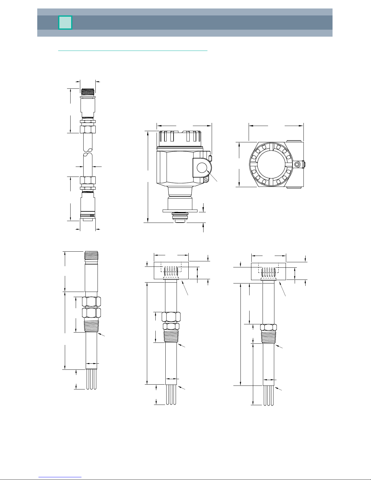
3 INSTALLATION AND MOUNTING
3.1 Dimensions
1.8 or 3.6 m
(6 or 12 feet)
2.8 mm
(1.1")
76 mm
(3.0")
76 mm
(3.0")
ø 18 mm
(0.7")
29 mm
(1.15")
Extended cable
for remote mounting
length
3/4 NPT
96 mm
(3.8")
96 mm
(3.8")
160 mm
(6.3")
80 mm
(3.2")
19 mm
(0.75")
Transmitter
housing
(side view)
Transmitter
housing
(top view)
51 mm
(2.00")
190 mm
(7.50")
Ø 19 mm
(0.75")
70 mm
(2.78")
32 mm
(1.25")
¾ NPT
nylon
compression
thread
Adjustable epoxy glass
probe and electrode
32 mm
(1.25")
20 mm
(0.78")
51 mm
(2.00")
29 mm
(1.16")
Ø 19 mm
(0.75")
Ø 60 mm
(2.36")
26 mm
(1.02")
¾ NPT
compression
thread
Adjustable stainless steel
probe and electrode
3 electrode
end cap
Thread for direct
mount only
Length 204 mm, 305 mm, 458 mm,
611 mm, 763 mm (8", 12", 18", 24", 30")
29 mm
(1.16")
Ø 60 mm
(2.36")
26 mm
(1.02")
20 mm
(0.78")
30.5 mm
(1.20")
Ø 19 mm
(0.75")
min.
25.4 mm
(1.00")
¾ NPT
thread
Fixed stainless steel
probe and electrode
Thread for direct
mount only
Insertion length
3 electrode
end cap
Length 204 mm, 305 mm, 458 mm,
611 mm, 763 mm (8", 12", 18", 24", 30")
CorrTran MV Corrosion Monitor
7
29 mm
(1.16")
Ø 60 mm
(2.36")
26 mm
(1.02")
20 mm
(0.78")
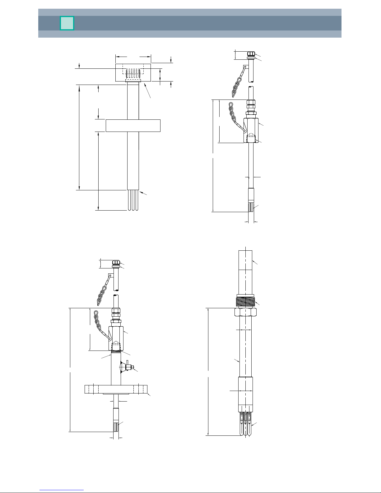
min.
50.8 mm
(2.00")
Thickness
ANSI B 16.5
standard
Stainless steel probe
with fixed flange
3 electrode
end cap
Thread for direct
mount only
Insertion length
Length 305 mm, 458 mm, 611 mm,
763 mm (12", 18", 24", 30")
(5.9")
I.L.
Six pin connector cap
Six pin circular connector
Ø5/8
Packing gland assembly
3x electrodes
(ordered separately)
Ø3/4
(1.6")
1" FNPT
Retractable probe & electrode,
remote mount
(5.9")
I.L.
Six pin connector cap
Six pin circular connector
Ø5/8
Packing gland assembly
(1.6")
Flange
1" NPT nipple
Bleed valve
Welded
3x electrodes
(ordered separately)
Ø3/4
Retractable flange & electrode,
remote mount
1-14 UNS-2A (L.H.)
Six pin circular connector
Ø5/8
Ø3/4
Insertion rod
3x electrodes
* specify alloy at
time of order
I.L.
Retrievable probe & electrode,
remote mount
CorrTran MV Corrosion Monitor
8
Six pin connector cap
Six pin receptacle assembly
1/2" NPT ø5/8" fitting
Ø5/8
Ø.7
Insertion rod
Blow out
preventer
(optional)
8"
Retrievable probe adapter,
remote mount
(3.88)
(5 1/4)
Hollow plug
assembly
Heavy protective cover
with 1/2" NPT
HP flareweld
access fitting
LPR probe
I.L.
Adj. probe exten. adapter
Retrievable probe complete
assembly, remote mount

CorrTran MV Corrosion Monitor
9
Figure 1. CMP Epoxy
Adjustable Probe
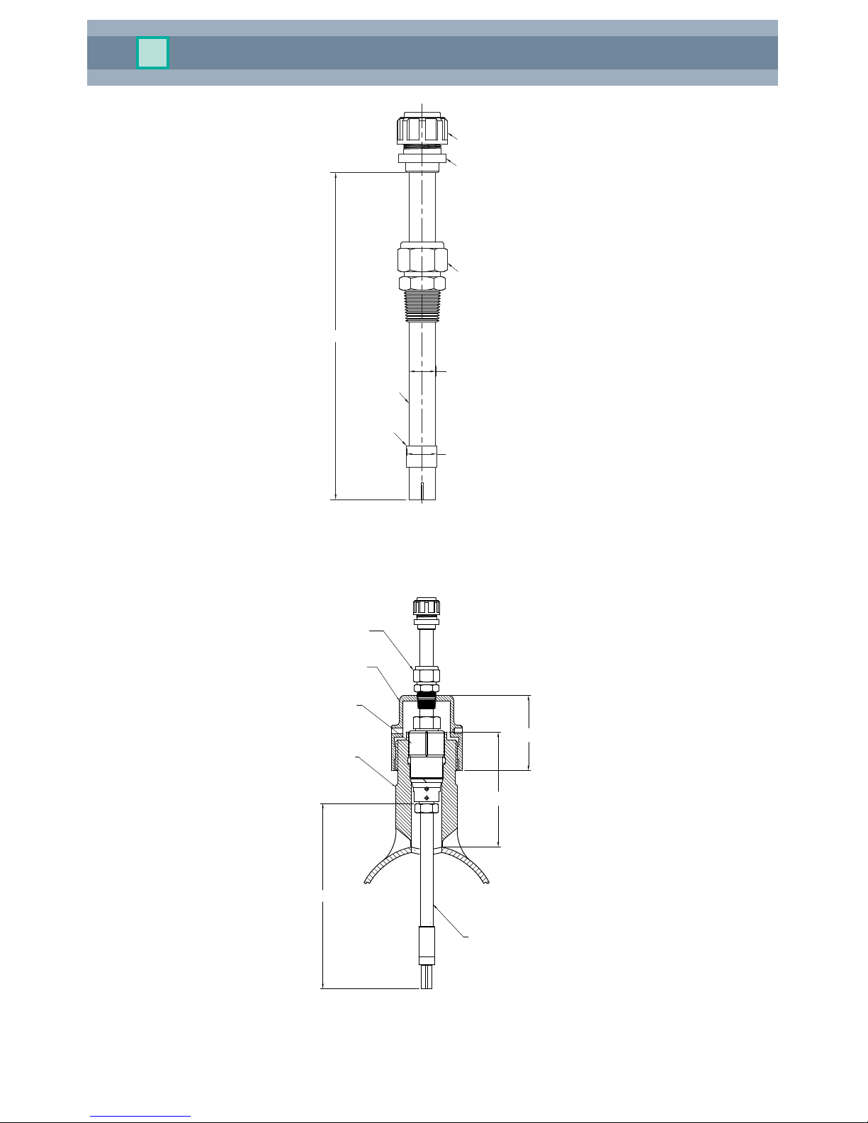
Figure 2. CMP
Adjustable Probe
3.2 Probe specications
CMP epoxy adjustable probe
The CMP epoxy adjustable probe (Figure 1) consists of a glass
epoxy probe with a ¾” NPT nylon compression tting for insertion
into the system. The studs for mounting the electrodes and the six-pin
connector are held in place by the epoxy ll material. This probe is
available in 127 mm and 280 mm (5” and 11”) lengths only. This probe
is only available with the remote mounting option.
Electrodes shown in the picture are ordered separately.
Specications
Probe Body Glass epoxy
Endcap Seal Epoxy
Fill Material Epoxy
Process Temperature -50…65 °C (-58…149 °F)
Pressure Rating 7 bar (100 psi)
Mounting 3/4” NPT nylon tting
Standard Lengths 127, 280 mm (5, 11”)
Custom Lengths N/A
Insertion Length Adjustable, Max = probe length - 89 mm (3.5”) + EL
*EL = 32 mm (1.25”) for nger and 0 mm (0”) for ush electrodes
CMP adjustable probe
The CMP adjustable probe (Figure 2) is an adjustable probe commonly
used in many eld applications. The assembly consists of a ¾” NPT
compression tting, an insertion rod with a hermetically sealed three-
electrode end cap, and a six-pin connector welded in place. The
insertion length is adjustable using the compression tting. This probe
is only available with both the remote and direct mounting options.
Electrodes shown in the picture are ordered separately.
Specications
Probe Body 1.4435, 316L SS; Hastelloy C
Endcap Seal Glass
Fill Material Epoxy
Process Temperature Direct mount: -50…121 °C (-58…250 °F)
Remote mount: -50…260 °C (-58…500 °F)
Pressure Rating 102 bar (1500 psi)
Mounting 3/4” NPT tting
Standard Lengths 204, 305, 457, 610 mm (8, 12, 18, 24”)
Custom Lengths Lengths available in increments of 10 mm (0.5”).
Min: 170 mm (7”), Max: 762 mm (30”)
Insertion Length Adjustable, Max = probe length - 51mm (2.0”) + EL
*EL = 32 mm (1.25”) for nger and 0 mm (0”) for ush electrodes
CorrTran MV Corrosion Monitor
10
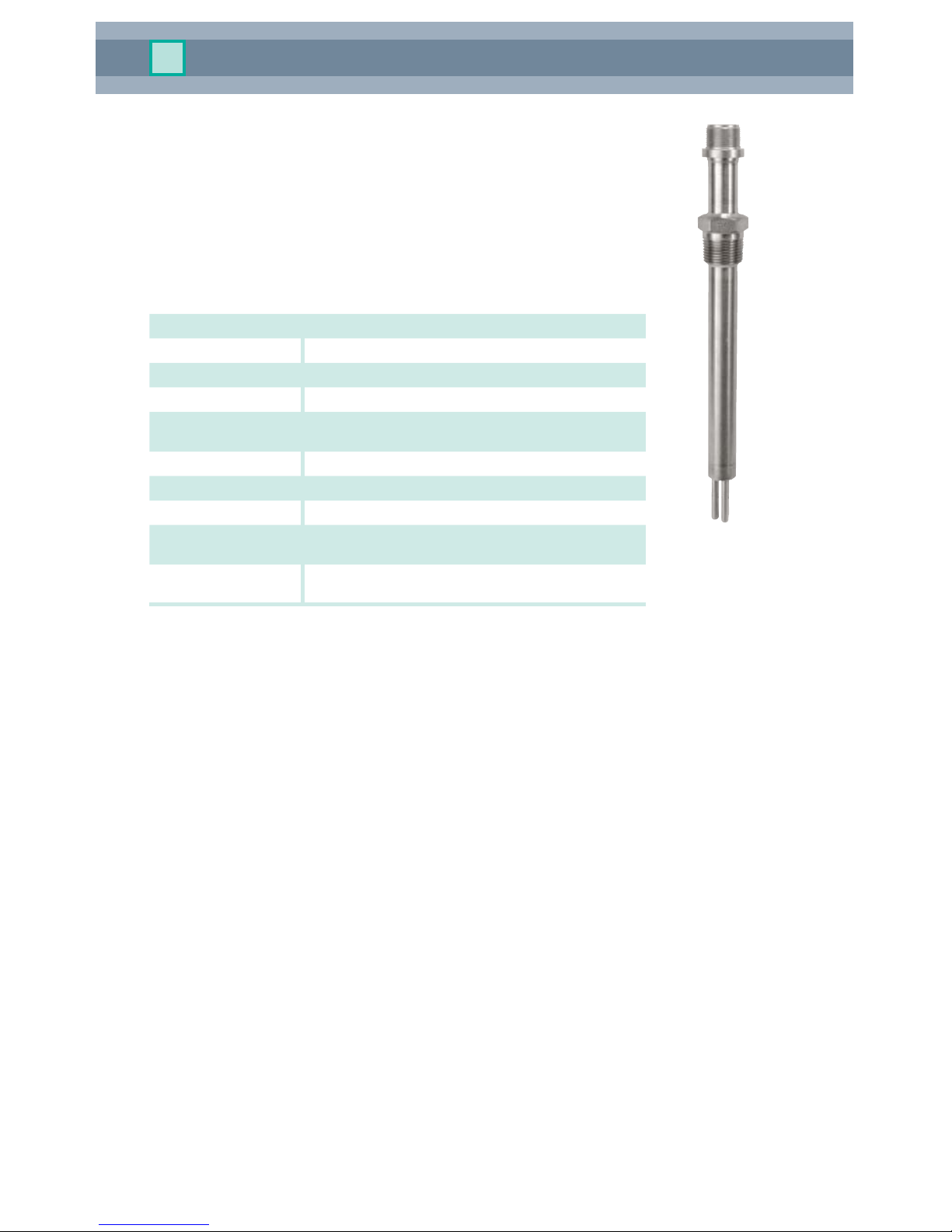
Figure 3. CMP
Fixed Probe
CMP xed probe
The CMP xed probe (Figure 3) is a xed-length probe. The probe
assembly consists of a ¾” NPT pipe plug that is welded in place, an
insertion rod with a three-electrode end cap, a hermetically sealed
connector, and a six-pin connector welded in place. The insertion
length (I. L.) is calculated to the end of the electrode and must be
specied by the customer. This probe is only available with both the
remote and direct mounting options.
Electrodes shown in the picture are ordered separately.
Specications
Probe Body 1.4435, 316L SS; Hastelloy C
Endcap Seal Glass
Fill Material Epoxy
Process Temperature Direct mount: -50…121 °C (-58…250 °F)
Remote mount: -50…260 °C (-58…500 °F)
Pressure Rating 206 bar (3000 psi)
Mounting 3/4” NPT tting
Standard Lengths 204, 305, 457, 610 mm (8, 12, 18, 24”)
Custom Lengths Lengths available in increments of 10 mm (0.5”).
Min: 170 mm (7”), Max: 762 mm (30”)
Insertion Length Fixed, Max = probe length - 38 mm (2.5”) + EL,
Length specied in 5 mm (0.2”) increments.
*EL = 32 mm (1.25”) for nger and 0 mm (0”) for ush electrodes

CorrTran MV Corrosion Monitor
11
CMP xed ange probe
The CMP xed ange probe (Figure 4) is a xed-length probe. The
probe assembly consists of a specied ange that is welded in place,
an insertion rod with a three-electrode end cap, a hermetically sealed
connector, and a six-pin connector welded in place. The insertion
length (I. L.) is calculated to the end of the electrode and must be
specied by the customer. This probe is only available with both the
remote and direct mounting options.
Electrodes shown in the picture are ordered separately.
Specications
Probe Body 1.4435, 316L SS; Hastelloy C
Endcap Seal Glass
Fill Material Epoxy
Process Temperature Direct mount: -50…121 °C (-58…250 °F)
Remote mount: -50…260 °C (-58…500 °F)
Pressure Rating 206 bar (3000 psi)
Mounting Flange connection
Standard Lengths 305, 457, 610 mm (12, 18, 24”)
Custom Lengths Lengths available in increments of 10 mm (0.5”).
Min: 170 mm (7”), Max: 762 mm (30”)
Insertion Length Fixed, Max = probe length - ange thickness - 50.4
mm (2.0”) + EL, Length specied in 5 mm (0.2”)
increments.
*EL = 32 mm (1.25”) for nger and 0 mm (0”) for ush electrodes
Figure 4. CMP
Fixed Flange Probe

CorrTran MV Corrosion Monitor
12
Figure 5. CMP
Retractable Probe
CMP retractable probe
The CMP retractable probe (Figure 5) is an adjustable-length
probe. A specially designed packing gland is used with the probe
for insertion into or retraction from a pressurized system without a
process shutdown. The packing gland is designed to mount easily
on a 1” piping system with a ball valve, but it can be modied for
your specic mounting requirements. The probe assembly consists
of a packing gland, an insertion rod with a hermetically sealed
three-electrode end cap, and a six-pin connector welded in place.
A safety chain is also provided to prevent blowout. The insertion
length (I. L.) is calculated to the end of the electrode and can be
specied by the customer. This probe is only available with the
remote mounting option.
Electrodes shown in the picture are ordered separately.
Specications
Probe Body 1.4435, 316L SS; Hastelloy C
Endcap Seal Glass
Fill Material Epoxy
Process Temperature Remote mount: -50…260 °C (-58…500 °F)
Pressure Rating 102 bar (1500 psi)
Mounting 3/4” NPT tting
Standard Lengths 610, 762, 914, 1066 mm (24, 30, 36, 42”)
Custom Lengths Lengths available in increments of 10 mm (0.5”).
Min: 170 mm (7”), Max: 762 mm (30”)
Insertion Length
Adjustable, Max = probe length - 165 mm (6.5”) + EL
*EL = 32 mm (1.25”) for nger and 0 mm (0”) for ush electrodes

CorrTran MV Corrosion Monitor
13
Figure 6. CMP
Retractable Probe
CMP retractable ange probe
The CMP retractable ange probe (Figure 6) is an adjustable-
length probe. A specially designed packing gland is used with
the probe for insertion into or retraction from a pressurized
system without a process shutdown. The packing gland
is welded to a 1” pipe nipple with bleed valve attached to
a specied ange, and is designed to mount easily on a
matching ange valve. The probe assembly consists of a
packing gland, 1” pipe nipple with bleed valve welded to
specied ange, an insertion rod with a hermetically sealed
three-electrode end cap, and a six-pin connector welded in
place. A safety chain is also provided to prevent blowout. The
insertion length (I. L.) is calculated to the end of the electrode
and can be specied by the customer. This probe is only
available with the remote mounting option.
Electrodes shown in the picture are ordered separately.
Specications
Probe Body 1.4435, 316L SS; Hastelloy C
Endcap Seal Glass
Fill Material Epoxy
Process Temperature Remote mount: -50…260 °C (-58…500 °F)
Pressure Rating 102 bar (1500 psi)
Mounting Flange connection
Standard Lengths 610, 762, 914, 1066 mm (24, 30, 36, 42”)
Custom Lengths Lengths available in increments of 10 mm (0.5”).
Min: 170 mm (7”), Max: 762 mm (30”)
Insertion Length Adjustable, Max = probe length - ange thickness -
255 mm (10”) + EL
*EL = 32 mm (1.25”) for nger and 0 mm (0”) for ush
CorrTran MV Corrosion Monitor
14
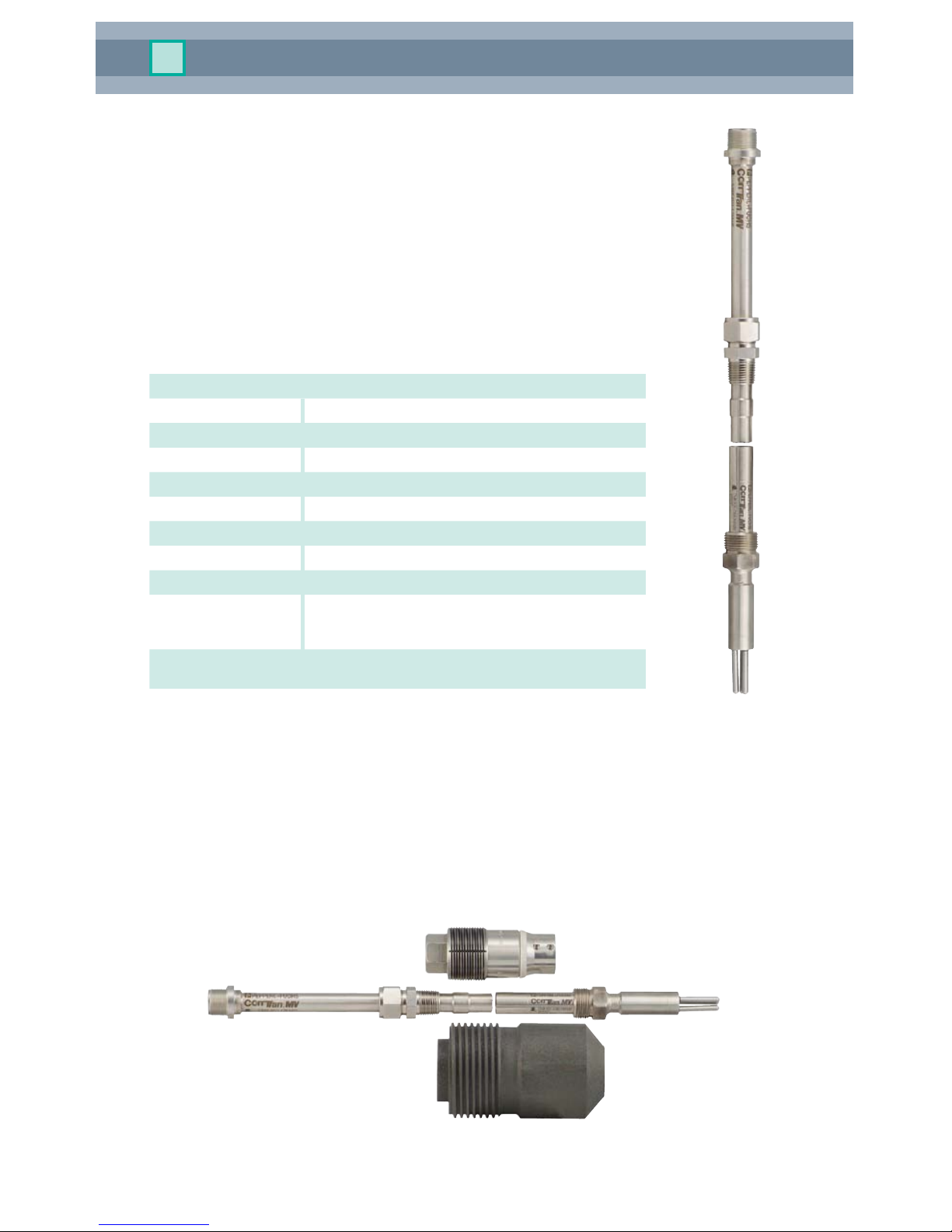
Figure 7. CMP
Retrievable Probe
and Probe Adapter
CMP retrievable probe
The CMP retrievable probe (Figure 7) is a xed-length probe. It is
designed to be used with HPTM and MHTM high-pressure access
systems. The probe assembly consists of an insertion rod with a
hermetically sealed three-electrode end cap, a hollow plug nut, and a
standard six-pin connector, which are all welded in place. The hollow plug
nut on the probe screws into the hollow plug of the access system. This
allows the probe to be installed in the process, using a retrieval tool and
service valve, without process shutdown. The insertion length (I. L.) is
calculated using one of the formulas bellow and must be specied by the
customer. This probe is only available with the remote mounting option.
Electrodes shown in the picture are ordered separately.
Specications
Probe Body 1.4435, 316L SS; Hastelloy C
Endcap Seal Glass
Fill Material Epoxy
Process Temperature Direct mount: -50…121 °C (-58…250 °F)
Remote mount: -50…260 °C (-58…500 °F)
Pressure Rating 245 bar (3600 psi)
Mounting UNS 1-14, 1” left-handed thread
Standard Lengths Length dependent on insertion length
Insertion Length
Finger Electrodes
Top-of-the-line: I.L. = PD + WT + 44.5 mm (1.75”)
Middle-of-the-line: I.L. = PD + WT + 22.25 mm (.875”)
Bottom-of-the-line: I.L. = PD + WT
Insertion Length
Flush Electrodes
I.L. = PD + WT + 44.5 mm (1.75”)
*EL = 32 mm (1.25”) for nger and 0 mm (0”) for ush
*PD = Penetration depth, for ush mount PD = 0
*WT = Wall thickness
Hollow plug and access tting are ordered separately.
CorrTran MV Corrosion Monitor
15
3.3 Mounting safety procedures and hints
The CorrTran MV must be installed in locations that are most susceptible to corrosion.
In most cases, the highest levels of corrosion tend to occur where water is trapped or
stagnant.
The electrodes selected must reect the same metal properties as the piping or other
components susceptible to corrosion. For example, in applications where the pipe is made
of stainless steel and the water pump’s impeller is made of carbon steel, the impeller will
corrode faster than the pipe. In this case, it is advisable to select electrodes that are made
of the same material as the pump’s impeller.
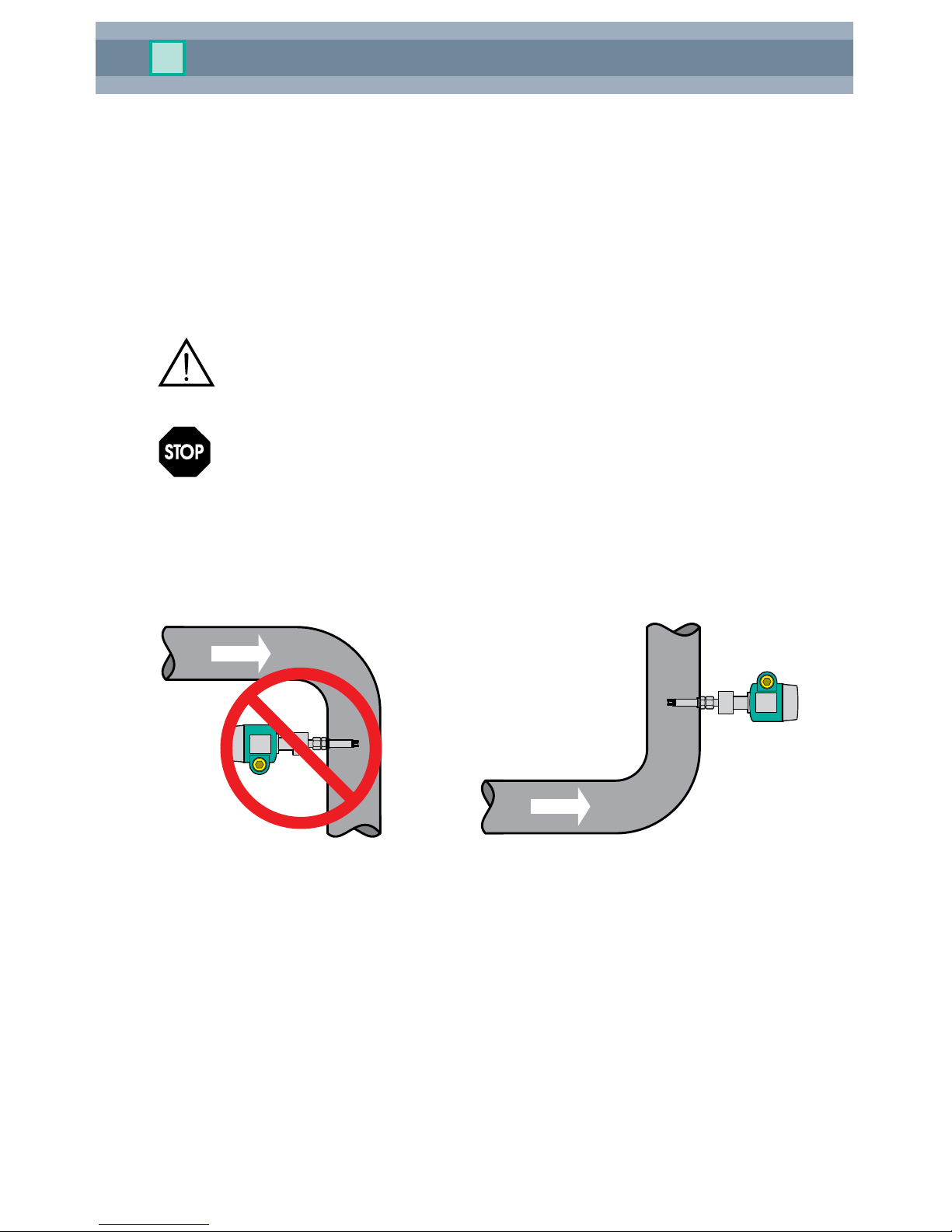
3.3.1 Mounting requirements / scenarios
The transmitter should not be mounted in a pipe drop since the corrosive liquid
may not be in full contact with the electrodes as shown in Figure 8.
CorrTran MV should be mounted in the riser of a pipe near an elbow where the
velocity is the highest. In general, CorrTran MV should be mounted in pipes
or tanks at locations of highest liquid velocity and constant immersion, shown
in Figure 9. For velocities greater than 20 fps, the protruding nger electrodes
must be protected. As noted above, high uid velocities can also cause unwanted
turbulence in the pipe due to the extension of the probe. Using an adjustable CorrTran MV
probe with electrodes mounted ush to the wall of the pipe will eliminate this problem.
Warning
Attention
OK!
Figure 8. CMC Transmitter Installation Figure 9. CMC Transmitter Installation
CorrTran MV Corrosion Monitor
16
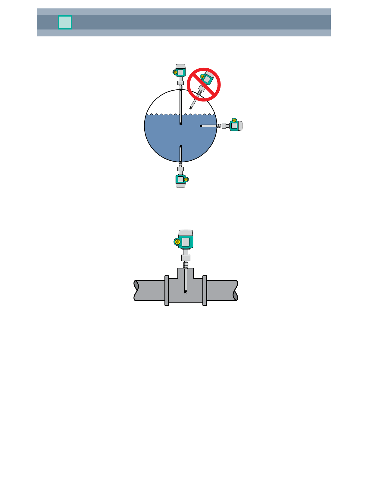
CorrTran MV can be located at any point on the pipeline but should always be immersed in
the corrosive material as shown in Figure 10.
Figure 10. Correct CorrTran MV Pipeline Position
A tee in the condensate return line (Figure 11) is a good location to mount CorrTran MV.
Figure 11. CorrTran MV Located in Tee

CorrTran MV Corrosion Monitor
17
CorrTran MV should be located downstream of a control valve for best performance and
can also be located in the deadleg portion of a by-pass. Note that the transmitter located
in the by-pass leg should be mounted in front of the valve for best performance. As shown
in Figure 12. This guarantees that the electrodes will always be immersed in the corrosive
material.
Figure 12. CorrTran MV Located in Bypass Loop
Installing separate CorrTran MV units with different electrode materials on the
suction side of the pump will ensure monitoring of the pump impeller and the pipe
as shown in Figure 13.
There should be a minimum separation distance of 50 cm (19.7”) between probes.
Figure 13. CorrTran MV Mounted With Different Electrodes
Note

CorrTran MV Corrosion Monitor
18
In addition to pipes, a condensate ash tank, shown in Figure 14, is also a good application.
Figure 14. CorrTran MV Installed in a Condensate Flash Tank
The CorrTran MV transmitter is shown in the blow down of a Y-strainer in Figure 15, and the
discharge side of the basket strainer is shown in Figure 16.
Figure 15. CorrTran MV Mounted in
Y-Strainer
Figure 16. CorrTran MV Mounted in
Basket Strainer
It is essential that isolators are installed between the transmitter and the control
system if the I/O card is not fully isolated from the ground. See section 4.3 for
more information on the proper installation wiring.
Note

CorrTran MV Corrosion Monitor
19
3.4 Installation instructions
3.4.1 General
A trained specialist must perform the necessary installation and commissioning
of CorrTran MV. Recognized rules of the technology and setup requirements
must be maintained both during and after installation. Safety requirements
must be observed during all installation steps.
If the pipe or vessel into which the CorrTran MV is to be inserted is under
pressure and/or contains any hazardous substance, such as steam, caustic
solutions, acids, toxins or other substances specied by OSHA as physical or
health hazards, the pipe or vessel must rst be depressurized, any hazardous
substance purged therefrom, and appropriate lockout/tagout procedures
observed in accordance with Section 1910.147 of the OSHA Regulations,
before CorrTran MV can be installed. Failure to follow these procedures may
result in serious injury or death.
CorrTran MV consists of three basic components:
Transmitter: A transmitter housing contains the electronics and provides the 4-20 mA with
HART output signal.
Probe: There are two basic options, direct mount and remote mount. The remote mount
probe is supplied with a 6’ or 12’ cable.
Electrodes: Either nger electrodes or electrodes ush to the probe end are used. Correctly
chosen electrodes will corrode in the same manner as the metal being investigated. For
accurate measurements, the electrodes must reect the same metal properties as the
metal being investigated.
3.4.2 Electrode installation
The electrodes are shipped loose and must be installed hand-tight. Ensure that the Viton
(standard) or Kalrez (on request) gaskets are in place prior to installing the electrodes. See
Figure 17 for the electrode installation drawing.
Metal Samples recommends changing the electrodes when they are at 50% of
their useful life:
• Finger:0.4mmmaterialloss.Thismeansthatwithanaveragegeneralcorrosion
rate of 16 mpy (0.4 mmpy) you would have to replace once a year.
• Flush:3.175mmmaterialloss.Thismeansthatwithanaveragegeneral
corrosion rate of 127 mpy (3.175 mmpy) you would have to replace once a year.
Figure 17. Electrodes and Viton Gaskets
Warning
Electrodes Viton Gaskets
Note
Table of contents
Popular Transmitter manuals by other brands


JAROLIFT
JAROLIFT TDRC01W Original assembly and operating instructions

Allmatic
Allmatic B.RO2 WALL quick start guide

Becker
Becker Centronic SunWindControl SWC441-II Assembly and operating instructions

Sennheiser
Sennheiser SK 250 Instrucciones para el uso

Phonic Ear
Phonic Ear 340T user guide

Ashcroft
Ashcroft ZT11 Installation and maintenance instructions


