11
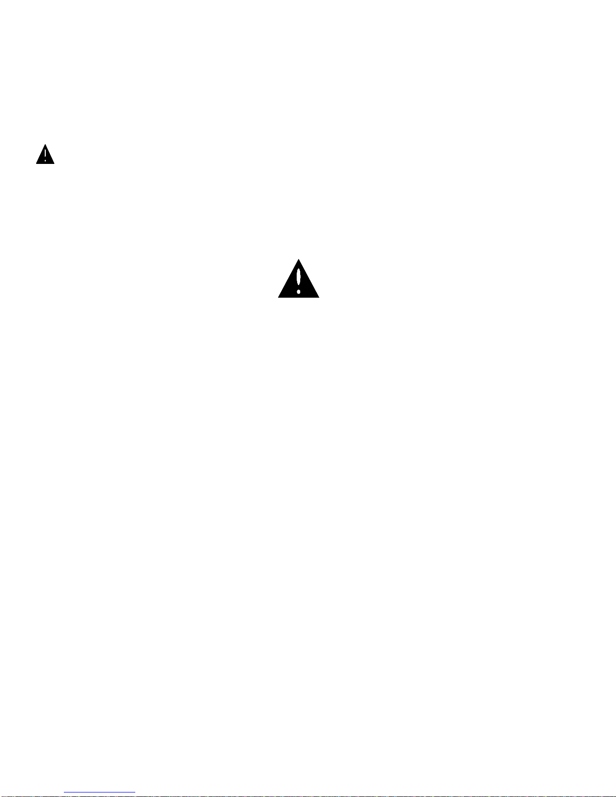
auger is not, switch incoming hydraulic lines or
refer to assembly instructions.
WARNING! BE SURE THAT ALL CLEAN-OUT
DOORS ARE CLOSED WHEN OPERATING. KEEP
HANDS, LOOSE CLOTHING, ETC. FROM MOVING
PARTS; FAILURE TO DO SO COULD RESULT IN
SERIOUS BODILY HARM.
8. Once the auger has begun to rotate, open
hopper door. Be sure to regulate flow from
gravity box into the hopper for optimum
performance.
NOTE: To achieve optimum performance, test by
placing auger at different angles. The position of the
auger depends on the type of material being handled.
NOTE: Use pressurized water to washout auger and
hopper after using fertilizer. See SERVICE section.
TRANSPORTING
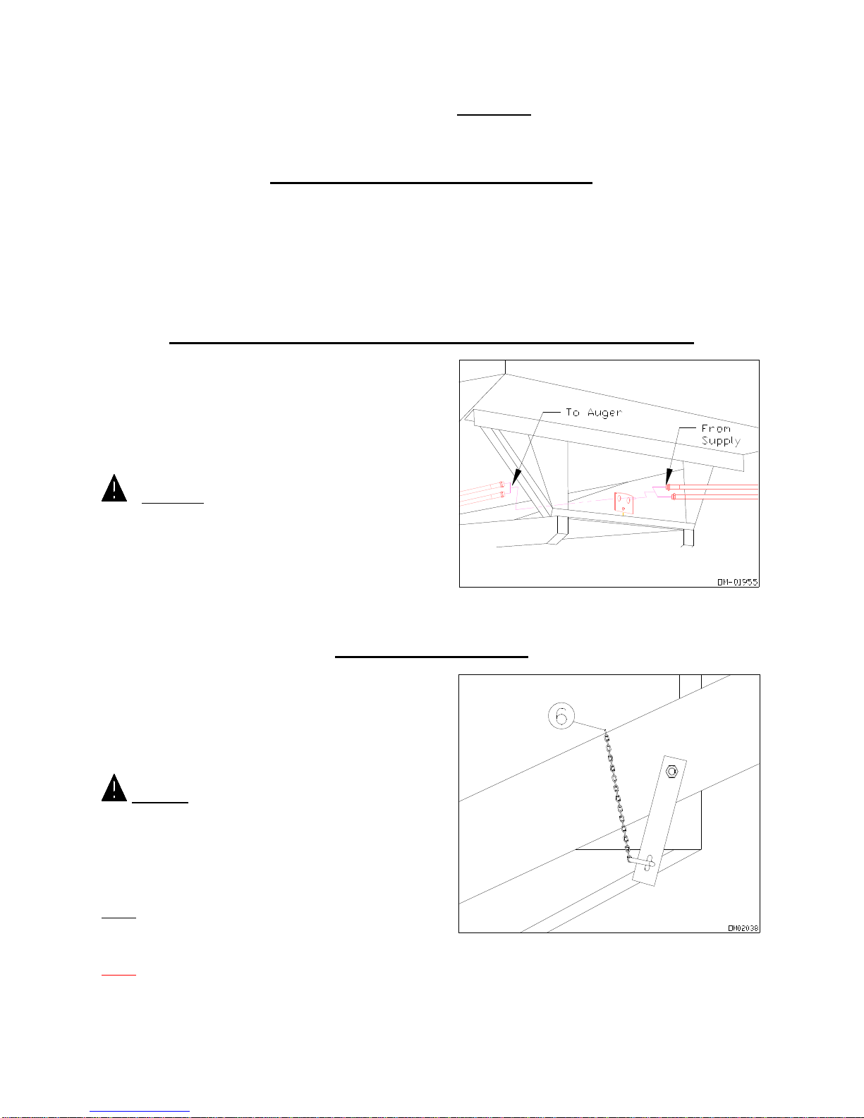
BEFORE TRANSPORTING
Be sure to completely empty auger by closing gravity
box door and allowing auger to run. Turn the auger
off and raise into position over transport bracket and
lower into position, while securely holding the winch
handle. Once in place, lock the winch and tighten
cable so that it is taut. Finally, reposition safety chain
around auger and secure.
NOTE: Auger must be empty before transporting,
failure to do so voids warranty.
DURING TRANSPORTING
IMPORTANT: Before transporting, be sure that auger
is securely mounted in transport bracket.
Use caution when traveling, do not attempt to
transport unit under low hanging tree branches
overhead telephone wires or electrical wires. Be
aware of transport height of unit or damage could
occur.
Comply with all state and local laws governing
highway safety and regulations when moving
equipment on public roads.
CAUTION! USE APPROVED LIGHTS,
REFLECTORS, AND DEVICES WHEN
TRANSPORTING AT NIGHT AND DURING
PERIODS OF POOR VISIBILITY.
WARNING! ALWAYS TRAVEL AT A SPEED
WHICH PERMITS COMPLETE CONTROL OF
EQUIPMENT.
PERFORMANCE
MAXIMUM OPERATING PRESSURES:
•Continuous 1500 psi (min. 1000 psi).
•Peak (10% of Duty Cycle) 2250 psi.
•Back Pressure 1000 psi.
•Maximum Oil Flow 12 GPM (min. 10 GPM).
•Recommended Oil Viscosity Range 100-200 S.S.U.
•Maximum Operating Temperature 180 degrees.
•Recommended Filtration 10 micron or finer.
NOTE: For hydraulic systems that exceed the recommended peak pressure or have greater than 12 GPM oil flow, a flow
control valve is recommended to bring the system down to the peak performance of the auger. The control valve will extend the
otherwise short life of the seals and motor of the auger. Contact your Killbros dealer for more information.
WARNING! BE SURE THAT THE OIL RESERVOIR OF THE HYDRAULIC SYSTEM IS REFILLED TO ITS PROPER
LEVEL AFTER AUGER IS PUT IN OPERATION.
AVOID:
•Large contamination particles in fluid such as machining chips or sand.
•Extreme high fluid temperatures that cause the motor to operate slowly and reduce the motor’s capability to lubricate
properly.