Killbros 575 User manual

1
OPERATOR’S MANUAL
PARTS CATALOG
MODEL 575 GRAIN CART
(After Serial # K4-1907 thru D1898)
24325 St. Rt. 697W
DELPHOS, OHIO 45833
PHONE: 419-695-2060
FAX: 419-695-6875
PART #105312

2
Table of Contents
INTRODUCTION..............................….3
SAFETY...........................................….. 4
OPERATIONS
ELECTRICAL HOOK-UP..................….7
TRACTOR HOOK-UP.......................….7
HYDRAULIC HOOK-UP...................….8
OPERATION IN FIELD.....................….8
OPERATING THE PTO....................….9
Coupling the P.T.O...............…10
Lubrication..........................….. 10
Chains.................................….. 10
Dismantling..........................….11
Assembling.........................….. 11
Slip Clutch...........................….. 11
IMPORTANT SCALE INFORMATION.. 12
OPERATING THE SCALE...............….13
SERVICE
LUBRICATION AND MAINTENANCE…15
SERVICE TIPS......................…......….. 15
AUGER SYSTEM...........................…… 16
FLOW CONTROL GATE…............…… 16
INDICATOR ARM..........................…… 16
ASSEMBLY
ASSEMBLY………………………….. 17
INSTALLATION OF HYD DRIVE.......... 18
INSTALLATION OF SCALE HITCH....…19
PARTS
AUGER COMPONENTS..………….20
FLOW CONTROL GATES...............…21
POWER TRAIN COMPONENTS.....….22
GEAR BOX DIAGRAM....................….. 23
POWER TAKE-OFF COMPONENTS. 24
AXLE/HUB COMPONENTS............….. 25
SCALE COMPONENTS...................….26
.
SIDEBOARDS.................................….. 27
LIGHT PACKAGE............................….. 28
MISCELLANEOUS...........................….29
DECALS...........................................….30
AUXILARY HYDRAULIC DRIVE UNIT.. 31

3
INTRODUCTION
Killbros Grain Carts are engineered to meet today’s challenging operating standards and the
needs of yours. With a rugged design throughout, this unit will keep maintenance to a minimum.
Keeping you busy with harvest and not repairs
This unit is not just standard; it features a wide variety of options to meet your field practices. This
unit offers various size bolt on axles for varying crop row widths and new tillage practices, with
little time to install. For up do date yield per acre and accumulated bushels per field, an optional
electronic scale package can do this from most anywhere in the field. To eliminate P.T.O.
attachment and improved safety, try the optional hydraulic drive kit.
With these options and standard equipment, Killbros Grain Carts add the efficiency, flexibility,
convenience, and dependability to succeed in today’s agriculture.
Please read and follow all information regarding safety, operating, and servicing instructions for
your new grain cart. Use this booklet to familiarize yourself and to get the maximum use of your
cart as it was designed to do. Please provide this booklet to other operators as well, for their
safety and efficient use. And again, Thank you for your purchase.
*Note: Determine right or left side of Grain Cart by looking in the direction of forward travel.
THANK YOU FOR YOUR PURCHASE!
Please fill out and retain this portion for your records. For warranty consideration, please contact
dealer where purchased.
The serial number is located on the right front standard, behind ladder.
Product: ______________________________________________________________________
Serial Number: ____________________ Date of Purchase: _____________________________
Dealer: _______________________ City: ________________ State: ________ Zip: __________
Please supply this information when you have questions or when ordering repair or replacement
parts. Your dealer needs this information to give you prompt, efficient service.
PRE-OPERATION CHECKLIST
!Wheel bolts tightened (re-check after initial use) !Safety and operating procedures reviewed
!Tire Pressure checked !Field adjustment information reviewed
!Hardware Tightened !Lubrication procedures reviewed
!Machine lubricated !Warranty information reviewed
!Guards and shields in place !Hydraulic hoses properly routed/fittings tight
NOTE: Due to continuing improvements in the design and manufacture of Killbros products and
normal changes in the marketplace, all specifications contained herein are subject to change without
notice.

4
No accident-prevention program can be successful without the whole-hearted cooperation
of the person who is directly responsible for the operation of the equipment.
To read accident reports from all over the country is to be convinced that a large number
of accidents can be prevented only by the operator anticipating the result before the accident is
caused and doing something about it. No power-driven equipment whether it is transportation or
processing, whether it is on the highway, in the harvest field, or in the industrial plant, can be safer
than the person who is at the controls. If accidents are to be prevented--and they can be
prevented--it will be done by the operators who accept the full measure of their responsibility.
It is true that the designer, the manufacturer, and the safety engineer can help; and they
will help, but their combined efforts can be wiped out by a single careless act of the operator.
It is said that, “The best kind of a safety device is a careful operator.” We, at Killbros ask
that you be that kind of operator.
Thank-You!
Killbros
REMEMBER:
THINK SAFETY
A CAREFUL OPERATOR IS THE
BEST INSURANCE AGAINST AN
ACCIDENT!

5
575 SAFETY DECALS
(For part numbers see pg. 30)

6
SAFETY
AVOID POSSIBLE INJURY
Always use safety precautions. Most accidents are a
result of failure to practice safety. Accidents cause
lost time and suffering. Do not operate the Grain Cart
without reading this manual thoroughly.
Follow all safety precautions as outlined in this
manual.
All machinery should be operated only by those who
are experienced and responsible and have been
delegated to do so.
BEFORE OPERATING
Be sure that all hardware is in place and properly
secured.
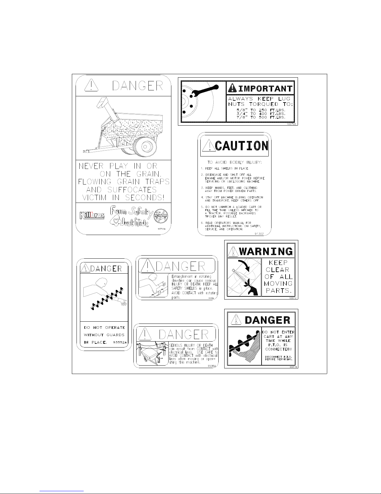
Keep safety signs clean and legible at all times.
Check tire pressure so that it is at the recommended
rating during operation.
Check box for any debris or excess grain before each
use.
Keep children and all unauthorized personnel clear of
work area.
Do not allow anyone to ride on the equipment. Make
sure everyone is clear before operating the machine
or tractor.
Always shut tractor engine off when working on the
unit.
Be sure that the clean-out doors are closed and
securely latched.
Keep body, hair, and clothing away from moving
parts.
DURING OPERATION
Keep children and all unauthorized personnel clear of
work area.
Never enter or climb on Grain Cart while the auger is
running.
Do not operate with safety shields removed or clean-
out door open.
Ensure that all personnel are clear before moving the
Cart.
Do not attempt to move any objects away from
moving parts.
Keep hands, feet, clothing, and objects away from
moving parts.
Do not grease equipment when in operation.
DO NOT allow ANYONE to enter the box at any time,
If entry is necessary, be sure chute door is closed,
P.T.O is disengaged, and tractor brakes are locked
before entry.
BEFORE TRANSPORT
Make sure that all safety decals and reflectors are
clean and in place on the machine.
While attaching cart to tractor be sure you can see the
driver and the driver can see you at all times to avoid
being struck by the tractor.
Comply with all state and local laws governing
highway safety when moving machinery.
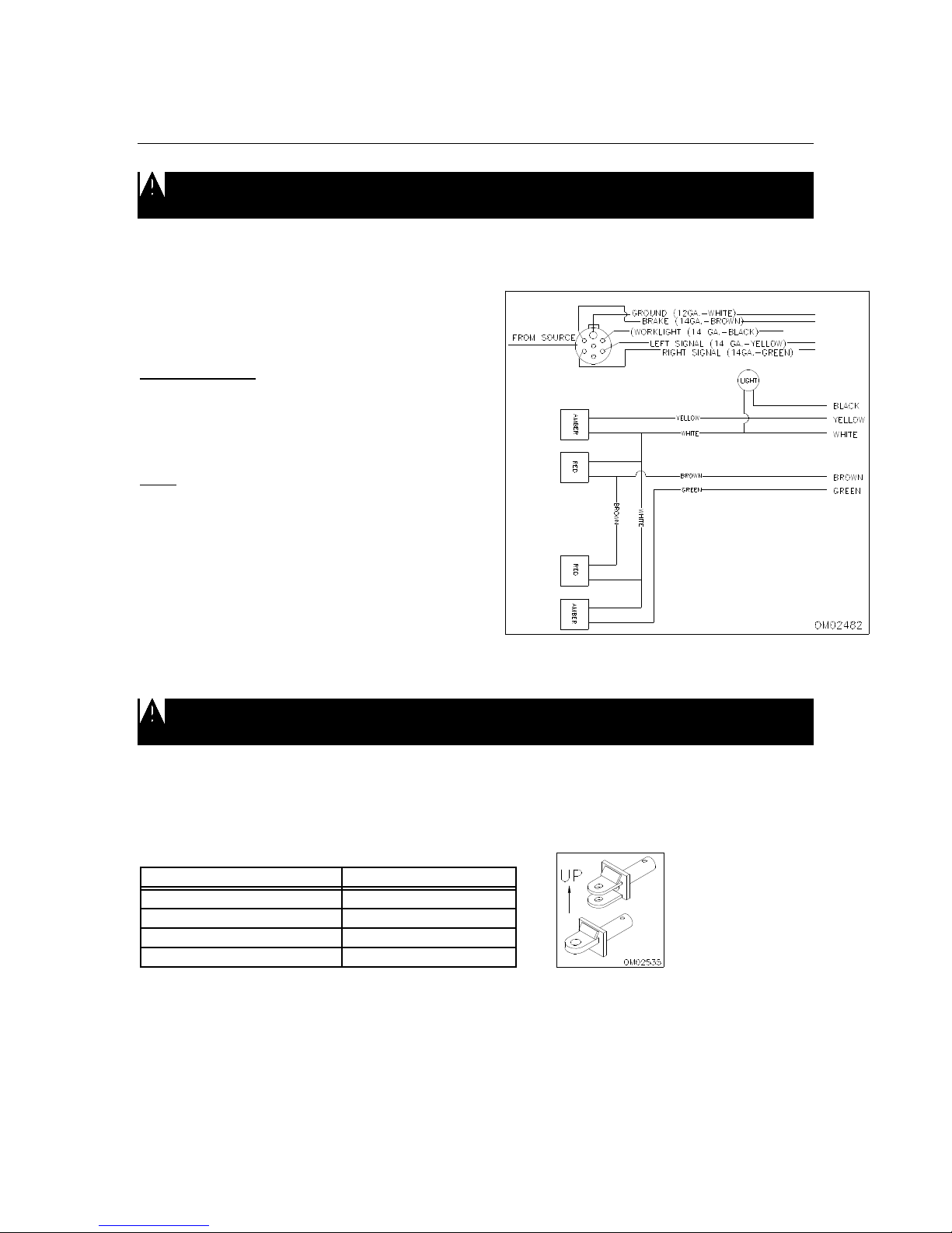
Use accessory lighting and warning lights when
transporting at night to adequately warn operators of
other vehicles.
When auger is not in use, be sure to fold to rest
position.
DURING TRANSPORT
Use good judgment when transporting implements on
highways. Maintain complete control at all times.
Regulate speed to road conditions.
Be careful when moving unit near electrical lines with
discharge auger up.
Drive at speeds slow enough to insure your safety as
well as others.
Regulate speed during off-road travel. Do not travel
faster than 8 M.P.H. loaded.
Due to the height and width of the implement, use
extra caution on highways, farm lanes, and when
approaching low and narrow clearances.
Follow all regulations concerning weight limitations on
roadways, bridges, and overpasses.
Unit is to be towed at tractor speeds only. 20 MPH
maximum.
COMPLY WITH ALL SAFETY WARNINGS AND
CAUTIONS IN THIS MANUAL

7
OPERATIONS
ELECTRICAL HOOK-UP
Do not attempt to install, attach, or repair any electrical applications on the cart if work area is wet.
Allow area to dry before any work is to be done. Electric shock or electrocution may result if area is not dry.
Your Grain Cart is supplied with a seven-point SAE connector plug, which will adapt to the
receptacle found on several new tractors on the market today. If not available, an SAE J S60A
seven-point outlet socket can be purchased from your Killbros dealer (order #104838).
SAE SEVEN POINT
CONNECTOR PLUG
Grain Cart Wires
White... Ground
Green.. Right amber flashing lamp
Yellow.. Left amber flashing lamp
Brown.. Tail Light
Note: It may be necessary to install a switch
in the tractor to operate the auger light.
The following schematic complies with
ANSI/ASAE Standard S279.9/SAEJ137 for
new production tractors. NOTE: Wiring
specifications may be different for older
tractor models. Consult your tractor
operator’s manual or dealer for proper wiring
and installation. (Figure 1)(Figure 1)
TRACTOR HOOK-UP
Make certain that you can see the driver and the driver can see you at all times to avoid being
struck by tractor while attempting to hook up the Cart.
- - Make sure sufficient counter-weight is used on the tractors front-end.
- - Move draw bar into shortest position.
Selecting the proper hitch pin size for your tractor!
Tractor Size
Hitch Pin Diameter
Category 4 (250-400 H.P.) 2"
Category 3 (110-250 H.P.) 1-1/2"
Category 2 (65-125 H.P.) 1-1/4"
Categroy 1 (Under 65 H.P.) 1"
* Information gathered form: ISO/TC2/SC2 N4123
- - With cart hitched to tractor, hook-up P.T.O. (see pg. 10-C), following all safety precautions.
- - Hook up 7-point electrical plug connection to tractor.
- - Be sure hitch is positioned as shown above. Gusset should be to top of hitch.
HYDRAULIC HOOK-UP

8
CAUTION! When coupling hyd. hoses to ports on tractor, be sure that coupler ends are clean of
dust, dirt and debris. Failure to do so could contaminate hydraulic system resulting in excessive wear and
possible failure.
- - Properly identify the hoses for the auger fold and the flow control operation.
- - It is advisable to use the hydraulic control lever closest to the operator (most commonly known
as control lever No. 1) to activate the flow control.
- - Once everything has been hooked up, test for any possible adjustments:
-Are tires inflated to proper pressure?
-Does Auger run smoothly?
-Does Dump Auger fully extend?
-Does P.T.O. operate properly?
-Is Slip Clutch set too loose or too tight?
-Does Flow Control Gate operate properly?
-Is Indicator Arm working properly?
-Are all lights working properly?
If any one of these is not adjusted properly please read the SERVICE section outlined in the
manual or contact your nearest Killbros dealer for further information.
With everything in good operating condition, be sure to close flow control gate before use.
OPERATION IN FIELD
The Grain Cart is not insulated. Keep away from all electrical lines and devices. Electrocution can
occur without direct contact.
1. Make sure the flow control door is in the closed position before loading into the cart.
2. Engage PTO at a low RPM; increase to 1000 RPM. It is not necessary to operate tractor at
full throttle while unloading. (Optimum speed is 850 RPM)
3. Open the flow control to desired rate.
4. Use the flow control opening to slow the rate of the flow rather than the tractor’s RPM. NOTE:
If overload causes the clutch to slip (standard PTO drive) or motor to stall (hydraulic drive),
close flow gate immediately. Excessive heating of the clutch will require replacement of
internal parts. Close flow control door and relieve auger unload pressure by opening bottom
pit dump door to remove some grain from auger.
5. Do not disengage the auger with the flow gate open. Excessive start-up torque may result,
putting stress on the cart driveline and your tractor.
6. Properly identify the tractor remotes for proper hook-up of the flow control and auger fold. A
mix-up can damage the auger drive system.
7. Under any circumstance, DO NOT enter the cart with the auger or tractor running.
8. It is strongly advised that the unloaded auger always be returned to the transport position
when not in use.
Operating the PTO
When finishing operation of PTO driven
equipment, shift PTO control to neutral, shut off
the engine and wait until the PTO stops before
getting off the tractor and disconnecting the
equipment.

9
Do not wear loose clothing when operating the
power take-off, or when near rotating equipment.
To avoid injury do not clean, adjust, unclog, or
service PTO driven equipment when the tractor
engine is running.
Never exceed the recommended operating
speed for the particular equipment in use.
PTO drive shafts must only be used for their
intended purpose.
PTO drive shafts, clutches, and freewheels are
designed for specific machine types and power
requirements. Other models must not replace
them.
NOTE: See the tractor and implement
manufacturers’ operating instructions.
Ensure that the PTO shaft is securely
connected.
A. Only use a completely shielded drive
system:
PTO drive systems with complete shielding
include the tractor master shield and
implement shielding installed all the time. If
any component of the shield system has
been removed for any reason it, or an
identical replacement part, must be installed
before operation.
B1
B. Maximum Joint Angles:
1. Joint (Standard Type)
Continuous operation 25 degrees
Short duration 45 degrees
Stationary 90 degrees
Check shaft articulation and clearance zone!
Joint articulations of more than 45 degrees
lead to damage. Contact between PTO drive
shaft and tractor or implement (e.g. three-
point hitch, drawbar) lead to damage.
C1
C. Coupling the PTO drive shaft (Fig. C1)
Twist-Collar Lock

10
1. Twist locking collar and simultaneously
push PTO drive shaft onto PTO shaft
until the locking device engages.
QD Pin-Lock (Not Shown)
2. Push locking pin and simultaneously
push PTO drive shaft onto PTO shaft
until the locking device engages.
Check to insure all the locks are secure
before engaging the PTO drive shaft.
D1
D2 D3
D. Lubrication (Figs. D1-D3)
Lubricate with quality grease before starting
work every 8 operating hours. Clean and
grease PTO drive shaft before each
prolonged period of non-use. Molded nipples
on the shield near each shield bearing are
intended as grease fittings and should be
lubricated every 8 hours of operation.
Telescoping members must have lubrication
to operate successfully regardless of
whether a grease fitting is provided for that
purpose. Telescoping members without
fittings should be pulled apart and grease
should be applied manually. Check and
grease guard tubes in winter to prevent
freezing.
E1 E2
E3
E. Chains (Figs. G1-G3)
NOTE: The chain is intended to prevent the
shield from rotating against non-moving
parts, thereby preventing shield damage. A
properly installed chain will increase the
service life of the shield.
1. Chains must be fitted to allow sufficient
articulation of the shaft in all working
positions. Care must be taken to be sure
that chain does not become entangled with
drawbar hitch or other restrictions during
operation or transport of machine
2. The PTO drive shaft must not be
suspended from the chain when PTO is not
in use or unattached from drive unit.
3. If chain should become unattached, do not
attempt to reattach it with the PTO engaged.
Turn off PTO and tractor engine before
making any repairs. If chain is missing
replace it before use.
F1 F2 F3
F. Dismantling guard:

11
1. Keep cone pressed downward and
release collar tabs by pushing with a
screwdriver. Push cone off tube.
2. Spread collar to remove from tube.
3. Slide tube off the shaft.
G1 G2
G3 G4
G. Assembling guard:
1. Grease collar groove and inner profile
tube.
2. Fit shield tube into collar by centering
the slots over the collar teeth.
3. Align cone, centering grease nipple to
grease filling hole on collar. Press
downward to connect.
4. Make sure the three collar tabs are
properly engaged by tapping on cone.
H. Slip Clutch - preset at factory
Damage may occur to other parts of the
grain cart if the spring tension is not set
properly. Correct operating procedure of the
slip clutch is to have it slip slightly with each
use.
1. If adjustment is necessary, length from
flange surface to underside of nut should
be 27.5 MM (1.15”).
2. Tighten nuts following an alternating
cross pattern until reaching the height
specified. Check that height is constant
for all springs.
3. If too much slippage occurs, only tighten
each nut a quarter of a turn at a time.
This quarter turn will increase the torque
approximately 500-750 inch lbs.
4. After extended time without use, the slip
clutch may freeze up. It is very important
at the beginning of each season to
loosen the nuts, slip the clutch, and
retighten the nuts to the correct length.
PLEASE READ THE
FOLLOWING INFORMATION
BEFORE USING YOUR SCALE!
THE FOLLOWING STEPS MUST BE CONSIDERED WHEN USING YOUR SCALE AND TO
REALIZE ITS BEST PERFORMANCE. DIGI-STAR SCALES ARE MANUFACTURED TO
PROVIDE ½% MAXIMUM ERROR. A GOOD INSTALLATION AND PROPER USE ARE
REQUIRED IN ORDER TO OBTAIN ADVERTISED ACCURACY.

12
A GOOD INSTALLATION REQUIRES THAT ALL LOAD CELLS BE PROPERLY INSTALLED
WITH “TOP” ACCURATELY POSITIONED.
OPERATION
TO INSURE + OR - ½% MAXIMUM ERROR, THE UNIT MUST BE USED AS A STATIONARY
LOAD-OUT WEIGH HOPPER FROM BIN TO TRUCK, FOR EXAMPLE, THE GROUND MUST
BE SMOOTH AND LEVEL WITH MAXIMUM 5” SLOPE PER 10 FEET.
TO INSURE + OR - 1% MAXIMUM ERROR, THE UNIT MUST BE USED SO THAT ALL
WEIGHT MEASUREMENTS OCCUR ON FLAT, SMOOTH GROUND (MAXIMUM OUT OF
LEVEL 10” IN 10 FEET) IDEALLY, ALL WEIGHT MEASUREMENTS FOR A FIELD WOULD
OCCUR IN THE SAME SPOT.
WARNING!
ALWAYS DISCONNECT CABLES
FROM SCALE INDICATOR BEFORE
JUMP STARTING ENGINE

13
Turn ON the scale:
1. Press [ON].
A brief message will be displayed (such as
“HELLO”). The scale then selects the
GROSS weighing mode.
GROSS mode displays the weight change
since the unit was last ZERO / BALANCED.
Pressing [ON] a second time during normal
system operation starts the self-test.
Turning OFF the Scale:
1. Press [OFF].
To Zero / Balance the Scale (Balancing):
1. Press the [NET / GROSS] key and
within three seconds.
2. Press the [ZERO] key.
The ZERO / BALANCE will “balance off” the
dead load such as a trailer, bin, or platform
weight.
“ZERO” is displayed to show completion of
the step and the scale is then placed in the
GROSS mode. If the supply power is below
the “low battery threshold” (10.5 Volts), the
message “INDICATOR CANNOT BE
ZERO/ BALANCED – LOW BATTERY
VOLTAGE” is displayed.
Pressing only the [ZERO] key will cause the
message “TO ZERO / BALANCE PRESS
NET / GROSS – THEN ZERO” to be
displayed.
NOTE: A “low battery” (below 10.5 Volts)
will activate the message “LO BAT”to be
periodically shown on the display (approx.
Every five seconds) to alert the operator of a
low battery.
To Select Gross Mode:
GROSS mode displays the weight change
since the unit was last ZERO / BALANCED.
1. Press [NET / GROSS].

14
NOTE: The scale is in GROSS mode if
there is a flashing arrow pointing toward the
GROSS text just above the [NET / GROSS]
key.
To Select Net Mode:
Net mode displays the weight change after a
TARE has been performed. TARE is a
temporary “zero” point.
1. If the scale “TARE” weight has not been
entered, press [TARE] to acquire a
“zero”.
OR
2. If in Gross mode, press [NET / GROSS].
The [NET / GROSS] is an alternating
action key. If the scale is in the GROSS
mode, pressing the [NET / GROSS] key
will place it in the NET mode. If the
scale is in the NET mode, pressing the
[NET / GROSS] will place it in the
GROSS mode.
If the “TARE” function has not been
previously performed, the unit will stay in the
Gross mode and the message “FOR NET
MODE PRESS TARE” will scroll across the
display.
NOTE: The scale is in the NET mode if
there is a flashing arrow pointing toward the
NET text just above the [TARE] key.
MODEL 150 - Optional Features:
Remote Display Options:
A Remote Display is available for viewing
weights at convenient locations. The
Remote Display includes a visual alarm light,
which can be used with the TR4 option listed
at right.
TR/TR4 Options: (Radio Control
Operation) The TR and TR4 options allow
the operator to remotely control the scale
from a distance up to 100 feet away.
The TR option allows the operator to
perform TARE and GROSS functions.
The TR4 option allows remote operation of
the RM (recall memory), M + (memory plus),
TARE, and either NET / GROSS or CM
(clear memory)
Contact J-Star or your J-Star dealer for
additional options.
Indicator Mounting:
The indicator is easily attached directly to the
cart by securing the bottom with two (2) bolts
1/4” x 3/4“ and nuts. Refer to page 19 for
further information.
Power Connection:
The power cable should be connected
directly to a vehicle battery or regulated
power supply. The scale end of the power
cable is attached to the J901 connector
located on the bottom panel of the scale.
Connect the RED wire from the power cable
to +12 VDC and the BLACK wire to
GROUND. The indicator is fused internally at
10 amps.
POWER CABLE CONNCTIONS:
WIRE COLOR WIRE FUNCTIONS
RED Battery (+12 VDC)
BLACK GROUND
ORANGE Remote Alarm Out+
BLUE Remote Input
Remote Alarm Connection:
If a remote 12 VDC alarm is to be used,
connect the + 12 VDC side of the alarm to
the power cable orange wire and the
GROUND side (or black wire) to the frame.
The alarm output is fused for a maximum
drain of 10 amps. The remote alarm
connection may also be used for motor
control purposes when used with a relay.
SCALE BOTTOM PANEL
CABLE CONNECTIONS:

15
Load Cell Connection:
The indicator is designed to operate with
strain gage load cells. The indicator will
normally be supplied with a “J-BOX” cable
going between the scale and the load cell
junction box. Extension Kits are available
from your dealer in various lengths.
To connect the load cells, attach the junction
box cable to the J902 connector on the
bottom panel of the scale. Connect the load
cell cables to the junction box as shown
below.
JUNCTION BOX LOAD CELL CABLE
CONNECTIONS:
SERVICE
LUBRICATION AND MAINTENANCE
To keep your grain cart in top operating condition and to get the maximum performance and
reliability, lubrication and a periodic inspection is a must.
The lubrication locations and recommended schedule are as follows:
Item Description
1Front, Center, Rear Bearings - Daily
2Replace every season, 2 quarts 90W oil
3Five shots of grease per season
4See page 10
5Repack once every 2 years;
adjust bearing take-up once per season
SERVICE TIPS
SELECTING PROPER TRACTOR FOR YOUR CART
Approximate loaded weight of cart - 34,500 lbs.
Approximate loaded hitch weight of cart - 3,300 lbs.

16
WHEEL NUTS
Check all wheel nuts for tightness before first load. Failure to do so may damage wheel nut seats.
Once seats are damaged, it will become impossible to keep nuts tight. Tighten nuts to 400 ft. Lbs.
Retighten after first three loads and check periodically during first season of use.
TIRE PRESSURE
The following is to be used as a general guide for tire inflation. Figures may vary depending on
specific brand of tire used. It is important that tires are inspected after unit is loaded. The tire
should stand up with no sidewall buckling as tire rolls.
23.1 x 26 35 P.S.I.
18.4 x 38 37 P.S.I.
20.8 x 38 37 P.S.I.
24.5 x 32 38 P.S.I.
U-JOINTS
The U-joint will give you many years of service if grease is applied to each joint and spline weekly.
GEAR BOX
To check fluid level, grain cart must be setting level.
-- The fluid level plug and fill plug is on the backside of the gearbox.
For maximum gear box life:
-- Check oil level every two weeks
-- Replace oil every season, fill to fluid level plug or 2 quarts 90 weight oil
AUGER SYSTEM
Annually check all bolts, nuts, and set
screws. Perform lubrication as specified.
The vertical auger screw on upper and lower
auger tubes are designed to self align while
extending upper auger. If misalignment
occurs, realignment can be made by
adjusting the hanger bearing, located at top
of lower auger. (See figure 2 for exact
location). If auger is still misaligned, check
the gearbox to see that all hardware is
secure and tight.
(Figure 2)
FLOW CONTROL GATE
The Flow Control Gate is designed to
prevent grain from putting an excess load on
the horizontal auger during initial start-up. If
gate is not working properly check:
- - the hyd. cylinder, making sure hoses are
attached properly, clevis pins are secure,
and fluid level in cylinder is at its
recommended level.
- - for any debris that may have wedged
between gate and auger tube.
- - indicator linkage. See that it is not binding
up.
INDICATOR ARM
The Indicator Arm lets the operator know the
position of the flow control gate, open or
closed. This arm is connected to the flow
control gate. If the indicator arm is not
working properly see that the hardware
connecting the linkage is secure and not
binding up. See flow control gate for further
adjustments.
ASSEMBLY

17
Some assembly is required before initial use
and operation. All Grain Carts come
shipped without the upper auger, work light,
and hydraulic cylinder and hoses installed. If
dealer hasn’t already installed all equipment
please refer to the following for proper
location and installation. Before operation,
double check to see that all components are
installed and working properly to prevent
damage to cart or personal injury.
All components of cart are shipped with cart
and stored in the least likely spot not to be
damaged during shipping. Cart is shipped
with 1 upper auger, 1 work light, 1 hyd.
cylinder, and 4 hyd. hoses. The upper auger
is noticeable, located behind the ladder. The
hydraulic hoses are secured with cable ties
around the ladder. The hydraulic cylinder in
located on the right frame channel directly
behind front frame standard. The work light
is located, opposite the hydraulic cylinder, in
a box taped to the channel support. See
(Figure 3) for locations.
(Figure 3)
Installation
Refer to (Figure 4). Remove hydraulic hoses
from ladder by cutting the cable ties used in
shipping. Be careful not to cut hoses. On
one end of each hose is a hydraulic coupler
that will attach to the tractor. Connect the
opposite end to the cart. (1) Connect the
four male hoses to the female fittings used
for the upper auger. To prevent damage to
these hoses, secure to outside rail of ladder.
(2) From ladder, run hoses through the U-
brackets welded along the inside channel for
further protection of the hydraulic hoses. (3)
Install the work light to the auger chute. For
hardware listing see pg. 28. Secure the light
to the brackets used for the upper
bearing.(4) Feed wire used for the light
through the channels welded to the chute
and backside of the upper auger. (5) Install
the upper auger so that it is in the rest
position, resting on the rest bracket located
to the back of the cart. Position auger, lining
up the holes where auger is hinged. Once
aligned secure hinge pin with expansion pin.
Refer to page 20 for hardware listing. Auger
screws will pre-align once upper auger is
extended. (6) Install hydraulic cylinder and
secure with cylinder pins and clips. Upper
auger may have to be slightly extended or
cylinder is extended for proper alignment of
cylinder pinholes. Connect the cylinder
hoses to the two ports located below the
lower auger tube. Secure all hardware,
wiring, and hydraulic hoses and check for
leaks.
(Figure 4)
INSTALLATION OF OPTIONAL
HYDRAULIC DRIVE
The optional hydraulic drive unit eliminates
use of P.T.O hook-up. Also available for this
kit is an optional anti-reversing kit

18
For fully operational hydraulic drive unit
tractor must:
- - be equipped with an optimum of a 30
G.P.M. hydraulic system
- - has hydraulic hook-up of at least 4 ports.
* Refer to pg. 31 for illustration.
Assembly (Standard Kit)
1. Secure motor to mounting plate with ½”
hardware. Ports “A” and “B” should be
on the left side of mounting bracket.
(Determine right or left side by looking in
direction of forward travel).
2. Attach universal joint to motor. After
attaching the universal to the motor,
slide the opposite end of universal onto
the gearbox. Slide the universal and
motor on as far as it will go and secure
universal joint and motor. Position the
mounting bracket so that the universal is
straight and level to the P.T.O. shaft.
3. Attach mounting plate to the mounting
bracket securing it with the 5/8”
hardware provided.
4. Attach male coupler in port “A” and male
elbow in port “B”. Attach swivel elbow to
male coupler
5. Attach 84” hydraulic hose to each elbow.
6. At opposite end of hose attach a male
coupler. Attach a quick disconnect to
each end of the male couplers. Secure
all hoses and check for any leaks.
7. Attach the “caution” decal to the
hydraulic drive kit to show proper
rotation of the auger.
Assembly (Anti-Reverse Kit)
1. Follow steps 1-4 in Standard Kit
assembly.
2. Connect 15” hydraulic hose to ends of
each elbow.
3. Before connecting tees to hose,
assemble anti-reverse valve and male
tees, as shown. NOTE: Teflon tapes or
paste will be needed on pipe threads.
Once assembled connect the 15” hoses
making sure the arrow on the valve is on
top and pointing to the left.
4. Connect 84” hydraulic hose to each
male tee.
5. At opposite end of hose attach a male
coupler. Attach a quick disconnect to
each end of the male couplers. Secure
hoses and check for any leaks.
INSTALLATION OF SCALE UNIT
HITCH ASSEMBLY
1. Remove the 3/4” x 5” bolt (105250),
lockwasher (100186), and nut (102521)
to remove the swivel hitch (102524).
2. Before installing the 2-1/8” weigh bar
(102694), feed the wire through the
scale insert bushing and the hole
indicated in figure 5. After wire has been
fed through, insert the 2-1/8” weigh bar.

19
3. To secure weigh bar to hitch reattach
hardware removed.
JUNCTION BOX INSTALLATION
1. Install Junction Box on the backside of
the right front frame standard (see
Figure 5).
2. See pages 14 and 15 for specific wiring
installation instructions.
SPINDLE ASSEMBLY
1. Use a 5-ton jack and jack stands to
support the weight of your grain cart.
Place the jack stands under the axle
near the tire.
2. Remove the tire and the hub assembly.
3. Remove the bolt, lockwasher, and
locknut to release the 3 3/8” dia.
Spindle.
4. Change the grease seal in the hub.
5. Using the same bolt, lockwasher, and
locknut just removed, add the 8 1/2”
spindle bushing and 2 7/8” dia. scale
spindle.
6. Attach hub assembly and original wheel
and tire.
NOTE: Tighten lug nuts to 400 ft. Lbs.
INDICATOR INSTALLATION
1. Locate Indicator box on topside of the
right front frame standard. *Note: Be
sure that the junction box is not directly
located behind indicator box while
drilling holes.
2. Indicator should be placed at eye level
toward top of the panel for convenient,
efficient use. (See Figure 5)
3. Mark cart for drill holes while holding
indicator in place. Be sure hole
alignment is level before drilling holes.
4. Drill holes and secure with hardware
provided.
(Figure5)
Auger Components

20
Item Part # Description Item Part # Description
1 100804 U.V.A Screw 15 102427 Cylinder Pin w/ Clips
291144-162 1/4" x 1-1/2" Expansion Pin 16 103443 Pilot Check Valve
39389-115 1/2" x 5" Bolt 17 103439 51" Hydraulic Hose
4 100719 Comp. Spring, 3-5/8" 18 102618 40" Hydraulic Hose
5 94981 1/2" Reversible Locknut 19 103441 3/8" Street Ell, 90 Degree
69405-088 1/2" Washer 20 102614 Bulkhead Union Elbow
7 100743 1-1/2" Flange Bearing 21 102617 Hyd. Hose, 15"
102204 1-1/2" Bearing Insert 22 102612 Hyd. Tube, 3/8" Formed
8 103816 U.V.A. Tube Assembly 23 102611 Cushion, Hyd. Tube
9 100784 3/8" Restrictor, 90 Degree 24 102654 Hyd. Tubing Bracket
10 103442 3/8" Male Run Tee 25 9389-007 1/4" x 1-1/2" Bolt
11 102680 Hinge Pin 26 9404-017 1/4" Lockwasher
12 102426 Hairpin Clip 27 9394-002 1/4" Nut
13 103437 19-3/8" Hydraulic Hose 28 102613 Hyd. Tube, 3/8" Formed
14 100782 2-1/2" x 8" Hyd. Cylinder 29 9390-060 3/8" x 2-1/4" HCS Gr. 5
101791 2-1/2" Hyd. Cyl. Repair Kit 30 9928 3/8" Locknut
Flow Control Components
Table of contents
Other Killbros Farm Equipment manuals