6TARGET ECO I FEEDING, rev.09
TARGET ECO I FEEDING
2SYSTEM’S OVERVIEW
2.1 Description of the controller
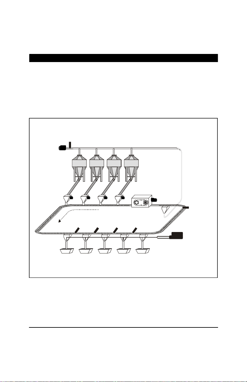
The ECOIFEEDING is an electronic device used to
distribute feed in hog barns. It is specially intended
for barns that are using a closed loop feeding system.
In all, the controller can distribute up to 8 different
types of rations. It can also adjust the composition
and the size of feed rations over time to suit the
animal’s needs.
The controller uses an external module called CDM-
1 to control the feeder motor and an external relay
panel to control the following outputs:
8ration augers;
96 drops;
1air compressor;
1actuator;
1cleanout auger;
9cleanout valves (1 master valve &
8 ration valves);
8timeclock outputs.
!
Refertothewiringdiagramenclosedat
the end of this manualtoconnectthe
variousdevices.
2.2 Main Features
Large LCD display
A large LCD screen offers an efficient interface for
displaying, monitoring and adjusting the parameters.
Individual control of 96 drops
Thecontroller can controlup to 96 independent feed
drops.
Actuator control for drops
The user can assign an actuator position to each
ration. This way, when a ration is delivered, the ac-
tuator open to the ration’s respective position, caus-
ing the opening of certain drops.
Ration curve
Ration curves provide an automatic adjustment of
the feeding periods and of the type of ration that is
distributed to the animals over time. It is thus pos-
sible to increase the number of feed cycles or to
switch rations as the animals grow up.
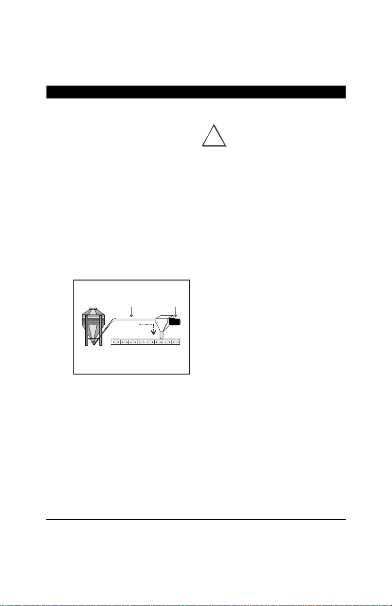
Cleanout
Cleanout periods allow evacuating feed leftovers
from the feed line. To evacuate the feed, the con-
troller restarts the feeder while the drops remain
opened. An optional cleanout auger can also be used
to send feed leftovers back to their original bin.
Animal inventory
The animal inventory function allows keeping track
of the number of animals in the barn. If drops are
controlled individually, the animal inventory is dis-
played separately for each one of them.
Fill auger run time
The controller has an history in which the run time
of each fill auger is recorded for the past 75 days.
8 clock outputs
The controller has 8 timers to control various de-
vices using the real-time clock.
Memory card
A memory card allows making a backup of the whole
controller configuration.
Alarm management
Weighing alarms are set off if a bin is empty and if any
kind of problem occurs on the distribution system.
Computer control
The controller can be connected to a computer, thus
making it possible to centralize the management of
information and diversify control strategies.