KiloVault HAB V3 Addendum User manual

KiloVault® HAB™ Series
Lithium Iron Phosphate (LiFePO4)
Deep Cycle Solar Battery
V3 Addendum
Please note. This document only contains information specific to the HAB™ V3,
pictured above. For complete instructions, please refer to the complete HAB™
Installation and Operation manual. The complete manual is downloadable from
www.kilovault.com.

02/22/2021
Overview 2
Installation 2
Unpack the HAB™ 2
Hab in the Crate 2
Crate Contents 3
Install the HAB™ Mounting Plate 4
Mounting Surface 4
Securing the HAB™ 5
Connect the HAB™ to Your Inverter 6
Physical Specifications 8
KiloVault® LLC • 330 Codman Hill Road, Boxborough, MA 01719 • +1 (888) 218-5924 • [email protected] • www.kilovault.com
1 of 9

Overview
We completely redesigned the KiloVault HAB™ case:
●The wiring panel of the HAB™ has been completely redesigned for your
convenience. There are ports on the left and right sides of the wiring panel, even
one on the top of the HAB™ . Power and communication cable connections are
easily made.
●The case has integrated handles that fold completely out of the way when
they’re not needed.
●The HAB™ now comes with vents that can be replaced with the included solid
plates.
○In cooler environments, replace the vents with the solid plates.
○In warmer environments, leave the vents in place.
Installation
Unpack the HAB™
Hab in the Crate
KiloVault® LLC • 330 Codman Hill Road, Boxborough, MA 01719 • +1 (888) 218-5924 • [email protected] • www.kilovault.com
2 of 9
HAB Beneith Foam Tray
Foam Tray with Accessories

Crate Contents
KiloVault® LLC • 330 Codman Hill Road, Boxborough, MA 01719 • +1 (888) 218-5924 • [email protected] • www.kilovault.com
3 of 9
Prior to installing your HAB™, please take pictures of the labels on the left side,
including the serial number, serial number barcode, QR code, and MAC
address. Store this information for your records, it is valuable and may be
necessary for system configuration or troubleshooting. Depending on your
HAB’s position, viewing this information after installation may be difficult.
It may be easier to open the tabs at the bottom (along the sides) of the box and
remove the box from the pallet, rather than removing the top lid and lifting the
HAB™ with the handles.
Part
Quantity
1.5-meter HAB™ to HAB™ CAN Bus communication cable (RJ11) Note: If a longer
cable is needed, it can be replaced with any telephone handset cord. RJ11 6
position, 4 conductor, male connectors both ends. Straight through. Maximum
length, 10 feet.
1
1.5-meter HAB™ to inverter Modbus communication cable to support a future
upgrade - Amphenol AT06 6S connector on one end, stripped wires on the other
1
RJ11 Clear Resistor Plug
1
Wall Mounting Plate
1
M8*30 mm Expanding Screw
10
M8*16 mm Bolt
2
28 mm Strain Relief
2
47.5 mm Strain Relief
1
Solid Vent Replacement Plates
4

Install the HAB™ Mounting Plate
Use the HAB™ mounting plate as a template to mark pilot holes on the mounting
surface. Choose holes so that you can mount the plate using at least four of the widely
spaced holes. Use a level to ensure that the plate is level. Refer to the Mounting
Surface section below for mounting surface specifications.
Mounting Surface
If you are anchoring the mounting plate into wood studs use at least four (one at each
corner) #14 (1/4") wood screws with washers. The screws must be long enough to
penetrate at least 1½" into the studs.
If you are anchoring into plywood wall material, the plywood must be at least ¾ inch
thick. Use four (one at each corner) #14 (1/4") wood screws with washers. The screws
must be long enough to penetrate at least ¼ inch beyond the back of the plywood. You
can also use four (one at each corner) heavy-duty ¼-inch toggle bolts, rated for at least
250 lb.
If you are anchoring into metal studs, the studs must be a minimum of 18 gauge. Use
at least four (one at each corner) #14 sheet metal screws with washers. The screws
must be long enough to penetrate at least three threads beyond the stud. If you’re
installing onto a wall with metal studs less than 18 gauge, a mounting surface (such as
KiloVault® LLC • 330 Codman Hill Road, Boxborough, MA 01719 • +1 (888) 218-5924 • [email protected] • www.kilovault.com
4 of 9
Wall Mounting Plate - See dimensions in the Physical
Specifications section.
Wall Mounting Plate attached to the back of the HAB.

a larger plywood surface to distribute the weight) must be attached to the wall prior to
installing the HAB™.
If you are anchoring into concrete or masonry, the minimum strength of the concrete
must be at least 2500 PSIwhile the minimum strength of the masonry must be at least
1500 PSI. Drill holes into the concrete or masonry with the 12 mm drill bit at the marks
you made earlier. Hammer the included M8* 30 mm expansion screws into the wall.
Attach the plate onto the wall with the M8 bolts.
Securing the HAB™
The HAB™ is heavy. It is approximately 230 lbs, and may cause serious back injury.
Use multiple people and/or lifting equipment to stably lift the HAB™ until the unit’s
upper and lower mounting flanges are just above the mounting plate’s upper and
lower lips and the HAB™ is between the mounting plate's arms. We strongly
recommend using lift equipment and straps to secure and steady the HAB™ during
installation.
Lower the HAB™ onto the mounting plate’s upper and lower lips, making sure that both
of the HAB™ unit’s upper and lower mounting flanges securely rest on both of the
mounting plate’s upper and lower lips. The holes in the mounting plate’s arms should
align with the lift handle screw holes. Attach the HAB™ to the mounting plate “ears”
using the included M8*16 mm bolts.
KiloVault® LLC • 330 Codman Hill Road, Boxborough, MA 01719 • +1 (888) 218-5924 • [email protected] • www.kilovault.com
5 of 9

Connect the HAB™ to Your Inverter
The wiring panel of the HAB has been redesigned to make the power and
communications connections easy.
There are access ports on the bottom left, bottom right, and on the bottom of the
HAB™ wiring panel. There is also an access port on the top of the HAB™ .
Two large and two small strain reliefs are included in the HAB™ packaging. Simply
remove the plugs from the access ports you want to use and replace them with the
strain reliefs.
KiloVault® LLC • 330 Codman Hill Road, Boxborough, MA 01719 • +1 (888) 218-5924 • [email protected] • www.kilovault.com
6 of 9
Wiring Panel with the Cover Removed
The Left side of the Wiring Panel
The Battery Connect Terminals
The Communication Connections

For detailed instructions on connecting your HAB™ to your inverter, please see the
complete HAB™ installation instructions. They can be downloaded from
www.kilovault.com.
KiloVault® LLC • 330 Codman Hill Road, Boxborough, MA 01719 • +1 (888) 218-5924 • [email protected] • www.kilovault.com
7 of 9
HAB Bottom Access Ports with Plugs in Place
Bottom Left Ports
Bottom Right Ports

Physical Specifications
KiloVault® LLC • 330 Codman Hill Road, Boxborough, MA 01719 • +1 (888) 218-5924 • [email protected] • www.kilovault.com
8 of 9
Item
Specification
HAB Weight
230 lb (105 kg) net
286 lb (130 kg) gross
HAB Height
32 in (812.8 mm)
HAB Width
22.5 in (571.5 mm)
HAB Depth
9.2 in (233.7 mm)
Mounting Plate Height
18 in (458.1 mm)
Mounting Plate Width
22.3 in (565.5 mm)
Mounting Plate Ears
1.7 in (42.5 mm)
Mounting Plate Lips
0.5 in (12.7 mm)
HAB Ingress Rating - Vents Installed
IP54
HAB Ingress Rating - Solid Plates Installed
IP55
Battery Terminal Torque
5.65 Nm, 4.17 ft-lb, 50 in-lbs
Table of contents
Other KiloVault Camera Accessories manuals

KiloVault
KiloVault HAB 7.5 V4 Instruction Manual
KiloVault
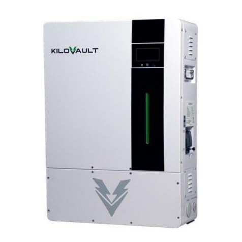
KiloVault HAB Series User manual

KiloVault
KiloVault HLX+ User manual

KiloVault
KiloVault HAB Series User manual

KiloVault
KiloVault HAB Series User manual

KiloVault
KiloVault 2100 PLC User manual

KiloVault
KiloVault HLX Series User manual
KiloVault
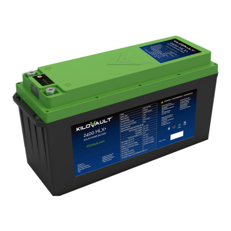
KiloVault HLX Series User manual