KiloVault HLX Series User manual

KiloVault®- HLX Series
Lithium Iron Phosphate (LiFePO4)
Deep Cycle Solar Batteries
Installation and User’s Manual
Release Date: August 13, 2019
Revision: 20190813

2 of 28
Contents
1. Safety Information ............................................................................................................................. 5
1.1. Definitions .................................................................................................................................. 5
1.2. Important Safety Information .................................................................................................... 5
2. Overview............................................................................................................................................ 7
2.1. Product Technology .................................................................................................................... 7
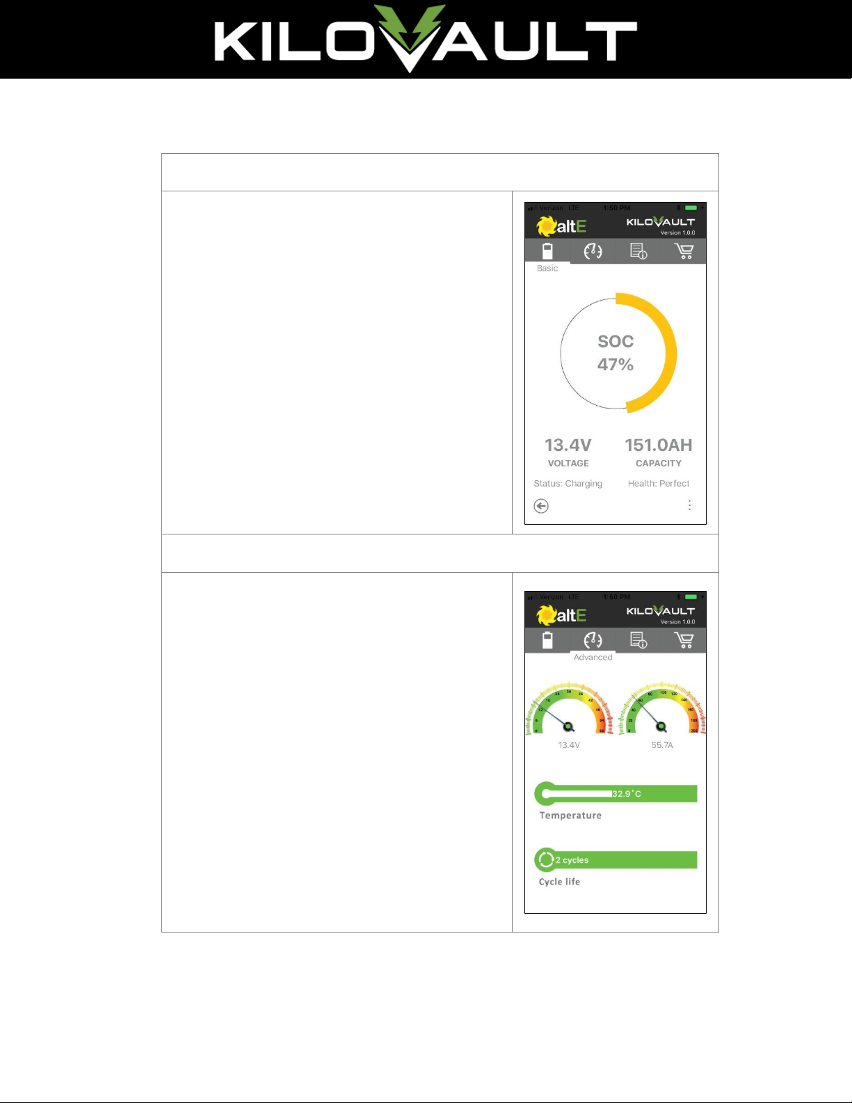
2.2. Bluetooth Monitoring Application ............................................................................................. 7
3. Installation Requirements ................................................................................................................. 9
3.1. Pre-Installation ........................................................................................................................... 9
3.1.1. All Batteries Must Be Fully Charged to the Same Voltage Prior to Use .............................. 9
3.1.2. Do Not Use DC Chargers Exceeding 150 Amps ................................................................. 10
3.1.3. Add Batteries of Exact Same Model Together .................................................................. 11
3.1.4. Disable Your Chargers Equalizing Cycle............................................................................. 11
3.1.5. Do Not Use a Battery Temperature Sensor (BTS).............................................................. 11
3.1.6. Temperature and Battery Physical Spacing....................................................................... 12
3.1.7. Insulating Battery Enclosure in Cold Temperatures.......................................................... 12
3.1.8. Battery Interconnect Cabling ............................................................................................ 12
3.1.9. Digital Voltmeters.............................................................................................................. 13
3.1.10. Environmental Conditions for Batteries ........................................................................ 13
3.2. Installation................................................................................................................................ 13
3.2.1. Configurations................................................................................................................... 13
3.2.2. Bolt Tightening .................................................................................................................. 14
4. Operation......................................................................................................................................... 15
4.1.1. Configuring Charge Controller & Inverter Voltage Set-points........................................... 15
4.1.2. Disable Equalization .......................................................................................................... 15
4.1.3. “Gel/Sealed Battery” Settings........................................................................................... 16
4.1.4. Energize Your Inverter First ............................................................................................... 16
4.1.5. Self-Protection Mode by the BMS..................................................................................... 16
4.1.6. Charge Rate ....................................................................................................................... 16
4.1.7. Temperature & BMS Self-Protection................................................................................. 16

3 of 28
4.1.8. Temperature & Effects on Battery Capacity...................................................................... 16
4.1.9. Charge Slower in Very Cold Conditions............................................................................. 17
4.1.10. Ensure Batteries Are at the Exact Same Resting Voltage Prior to Operation ................ 17
4.1.11. Ensure Parallel Rows of Batteries are Within 0.2V of Each Other................................. 17
5. Specifications................................................................................................................................... 18
6. Storage and Re-Commissioning....................................................................................................... 20
6.1. Disconnect Batteries for Long Term Storage ............................................................................ 20
6.2. Self-Discharge & Maximum Period Between Charging ............................................................ 20
6.3. Temperature & Humidity.......................................................................................................... 20
6.4. Avoid Using Trickle Chargers .................................................................................................... 20
6.5. Re-Commissioning.................................................................................................................... 20
7. Certifications.................................................................................................................................... 22
8. Disposal............................................................................................................................................ 23
9. Troubleshooting and Q&A ............................................................................................................... 24

4 of 28
The KiloVault® HLX series of solar lithium batteries are specifically designed and tested for the beating
that serious hybrid, off-grid inverters, and solar charge controllers can throw at them. Compared to
traditional deep cycle batteries, the HLX Series’ lithium battery technology more efficiently stores and
delivers the renewable energy that you have generated, with no maintenance on your part.
This manual contains important information regarding the safe use of KiloVault® HLX series batteries.
Your battery is an electrical device that will provide years of useful service with proper care. Ensure you
read and understand the instructions contained in this manual before use.
•Flexible: Works in 12Volt (V), 24V, or 48V configurations
•Gives You More: Use the full battery capacity, discharging it 100%
•Long-life: Even after 2000 full discharges, 80% of the total battery capacity remains
•Maintenance Free: No watering or cleaning of hazardous chemicals required
•High Efficiency: Providing up to 12% more useable stored energy
•Smart Investment: Lower cost per watt-hour/cycle and longer lifespan than lead batteries
•Safer: No thermal run-away issues as with other lithium technologies
•Heavy Duty: Takes up to 150 Amp (A) of continuous charging/discharging current, meeting the
tough demands of serious inverters and chargers
•Integrated Battery Management System (BMS)
•Bluetooth Monitor Application
•3-Year Limited Warranty
KiloVault, LLC
330 Codman Hill Rd
Boxborough, MA 01719
USA
Toll Free: +1.888.218.5924
www.KiloVault.com

5 of 28
1. Safety Information
1.1. Definitions
Warning:
Indicates a condition that can cause personal risk or injury.
Caution:
Indicates a condition that can cause equipment damage.
Note:
Indicates points of particular emphasis that make operation more efficient or
convenient.
Disclaimer:
Indicates information limiting the scope of responsibility.
1.2. Important Safety Information
It is essential to read, understand, and follow these instructions when using KiloVault® batteries.
Warning:
High voltage risk, improper use may cause personal injury or death.
Warning:
Do not use a battery that appears damaged in any way.
Warning:
All batteries present the risk of shock, use protective measures when handling.
•When working with or installing batteries use electrically insulated gloves and
tools
•Remove personal metal items such as watches, rings, bracelets, etc.
Warning:
High voltage connections of batteries (configurations of greater than 36V DC nominal)
are dangerous. DC voltages over 52V can stop the adult human heart and a fully charged
48V nominal system is over this level. Use appropriate safety measures including the
removal of metal personal items and insulated gloves.

6 of 28
Warning:
A small risk of spark exists while making electrical connections.
•Ensure the installation area is free of explosive gasses and liquids.
•Ensure the batteries are not installed in confined areas containing explosive
substances. This includes flammable fuel powered machinery, holding tanks, pipe
fittings, and connectors.
Warning:
In the unlikely event of a fire, when possible first shut off the source of electricity. Class
ABC extinguishers are recommended in close proximity of your power generating
equipment and are best suited for multipurpose fire types such as wood, flammable
liquids, and electrical appliances.
Warning:
Respiratory irritation may be caused if the battery is punctured or cracked.
Warning:
Skin contact with a punctured or otherwise open battery can cause irritation.
Warning:
To avoid risk of shock or fire, ensure all wires are properly sized and in good condition.
Warning:
Verify all equipment to be connected to the batteries is turned off before making any
electrical connections.
Warning:
Do not submerge the batteries. This can cause personal injury and will void your
warranty.
Warning:
Do not attempt to disassemble the batteries. This can cause personal injury and will
void your warranty.

7 of 28
2. Overview
2.1. Product Technology
•12 Volt Lithium Iron Phosphate (LiFeP04) with Bluetooth
•Model Types: KLV1800HLX (150Ah/1800Wh) / KLV3800HLX (300Ah/3600Wh)
•LiFeP04 chemistry prevents thermal runaway as opposed to other lithium technologies.
•IP55 Rated
•KiloVault® batteries can be used in RV applications for electrical appliances ONLY. They can NOT be
used to crank over motors in such vehicles.
2.2. Battery Management System
Every KiloVault® battery contains a BMS that helps protect it from over voltage charging/discharging,
over current charging/discharging, and extreme temperatures while charging and discharging. While
this system is robust, batteries must be installed using appropriate inverter charge controller settings,
devices to protect them from open photovoltaic (PV)/solar panel voltage, and other high voltage
charging sources. Failure to adhere to proper installation requirements will void the warranty and
may damage the system.
2.3. Bluetooth Monitoring Application
The KiloVault® smartphone Bluetooth app enables you to view general information about the selected
individual battery. It can help troubleshoot when attempting to detect the cause of the battery bank
going off-line. The app is available for free download for both Android and iPhone phones. Each
battery is identified by a unique serial number located on the battery label.
Disclaimer:
The KiloVault® Bluetooth Application is provided as is and is solely intended to gather
general information. It is not intended to replace a volt meter, nor guaranteed to work
with every device.
Note:
Your Android/iPhone must support Bluetooth Low Energy (BLE). Additionally, for the
Android app to work you must permit access to Location and Local Storage.

8 of 28
The information displayed includes:
Basic View
•State of Charge (SOC)
•Voltage
•Capacity
•Status (Charging/Discharging/Standby)
•Health
Advanced View (swipe right to access)
•Voltage
•Amps (Charging or Discharging)
•Temperature (Internal Battery Temperature)
•Cycle life (Number of times cycled)

9 of 28
3. Installation Requirements
3.1. Pre-Installation
IMPORTANT - PLEASE READ FIRST!
1) Each battery must be individually charged to exactly a voltage between 14.1V and 14.2V
(choose one and use it for all batteries) before placing it into operation with other batteries.
Otherwise, the batteries will independently hit full or empty and shut off before others in the
same battery bank.
2) Equalization charging must be turned off in your solar charge controller or AC charger. If left
on, the equalization charge will raise the voltage too high, damage the batteries, and void the
warranty.
3) Bulk/Absorption charge voltage should be set to no higher than 14.1V for a 12V system, 28.2V
for 24V system, and 56.4V for a 48V system (and lower for high amp chargers). Anything
higher risks one or more batteries automatically shutting off in a high voltage protection mode.
4) Low Voltage Cut-Off on the inverter should be set for no lower than 12.0V, 24.0V and 48.0V for
a 12V, 24V and 48V system, respectively. Voltages lower than this risks one or more batteries
automatically shutting off in a low voltage protection mode.
5) When turning on breakers to inverters, charge controllers, battery monitors, etc. connected to
the batteries wait 45-60 seconds between powering up each device. The KiloVault® battery
management system has special circuitry designed to detect short circuits and protect the
battery. Many brands of inverters, charge controllers and battery monitors will present a very
high but very brief surge that can be interpreted as a short. The BMS can handle one of these
perceived shorts every 45-60 seconds. Alternatively, in most circumstances all devices can be
powered up at once but the batteries will go into auto-protect mode and turn off for 30-60
seconds but then restart normally.
6) Be sure to tighten the battery terminals before operating. Failure to do so will lead to the
terminals overheating, melting the case, and potentially causing a fire.
Note:
Due to transportation regulations, LiFePO4 batteries cannot be shipped fully charged. As
a result, if you have purchased more than one battery for your system all batteries must
be fully charged to exactly the same voltage before using.
3.1.1. All Batteries Must Be Fully Charged to the Same Voltage Prior to Use
It is very important that each battery be individually charged to exactly the same voltage initially and
not less than 14.1 volts before putting the batteries into operation (not applicable if you are using only
one battery). Selecting a voltage at 14.1 to 14.2V is recommended but alternatively a precisely
selected low voltage will work, such as one between 11.5-12.0V.

10 of 28
Note:
After a 12 to 24 hour rest period following the initial charge the voltage will drop to
approximately 13.3-13.6V. This is normal, the batteries will not require re-charging. The
same holds true when drawing down the batteries. Once the batteries hit the
determined low voltage point and the load is disconnected, the voltages will rise back
up.
Do not charge the batteries initially to just 13.0 - 13.9 volts. There is a very gradual charge voltage
versus capacity curve when charging, especially between 13.6 to 13.9V. Charging them to a value in
this range (unlike lead acid batteries) can result in a very broad difference in the actual state of charge
versus any other battery in your bank. As a result, any one battery in your bank will prematurely shut
down during charging or discharging. See the charging graph below to understand the characteristics
of the LiFePO4 charging curves.
Many automotive type battery chargers will not reach 14.1V. Please check charger specifications
when selecting your charger or you can contact your KiloVault® distributor for a list of recommended
chargers.
3.1.2. Do Not Use DC Chargers Exceeding 150 Amps
Although a nominal charge rate of 100A is recommended on an on-going basis, you can use whatever
is available as long as it does not exceed 150A. After the charger is removed for the initial pre-
installation charge, allow them to rest for a minimum of two hours.
Note:
After the 2-hour rest period, use a DC Voltage meter to ensure that the voltage
difference between each of the batteries is not more than 0.2 volts. Failure to take these
preliminary charging steps will result in reduced capacity, make the batteries
prematurely shutdown during charging or discharging, and could void your warranty.
If the batteries are not charged to exactly the same voltage (preferably above 14.0V), then they are
not truly all at the same state-of-charge. As a result, the BMS in one or more batteries will
protectively shutdown the battery because it has either reached its high voltage maximum ahead of
the other batteries, or prematurely reached its completely discharged voltage. This situation protects
the battery bank by placing it into an open condition.

11 of 28
Figure 1: Voltage vs. Charge
There is very little voltage difference between 10% and 95% full in LiFePO4 batteries. To ensure
batteries are at the same charge level they all must be initially charged to the same voltage at the tail
upper end.
3.1.3. Add Batteries of Exact Same Model Together
Caution:
All batteries in a bank must be the same model. Mixing different batteries will result in
unexpected shutdowns and possible damage to the system.
When expanding your battery bank only combine the same model batteries together. Do not mix and
match different models or brands. Doing so will result in the batteries unexpectedly shutting down
and possibly cause damage.
3.1.4. Disable Your Chargers Equalizing Cycle
Caution:
Disable charge equalizing to prevent damage to your system.
If equipped, charge equalizing must be disabled in your charge controller(s), including the one in your
inverter, if it has one.
3.1.5. Do Not Use a Battery Temperature Sensor (BTS)
Caution:

12 of 28
Battery Temperature Sensors are not compatible with lithium batteries and will cause
damage to your system.
A BTS is often used by battery chargers in lead acid batteries because the “full” voltage changes with
temperature. This technology is not compatible with lithium batteries and must not be used. Using a
BTS is likely to cause the charge controller to over-charge the KiloVault® battery and damage it.
3.1.6. Temperature and Battery Physical Spacing
Because the batteries warm up while in use, you will want to consider your local average and seasonal
temperature when positioning your battery bank. If they will be in a warmer environment you may
want to leave a minimum of one inch between each of the batteries. If they will possibly be subject to
cold temperatures you may want to place them as closely as possible to each other. Please note that
the batteries can discharge several degrees below freezing but they will not charge.
3.1.7. Insulating Battery Enclosure in Cold Temperatures
Insulation around the batteries should also be considered for winter time if the batteries will be
exposed to temperatures that approach 32°F (0°C). Below freezing the BMS will not allow charging to
prevent damage to the cells.
Note:
The battery capacity reduces by 20% between room temperature and just above
freezing. Lead acid based batteries reduce capacity by 50% over the same temperature
range.
Using an insulated enclosure during these cold periods will maintain more of the heat generated
during normal charging and reduce the chances of the BMS shutting down the batteries in cold
temperatures. However, please make sure to remove the insulation in the hot months, as overheating
the batteries will shorten their life and the BMS will shut down the battery in temperatures above
149°F (65°C).
3.1.8. Battery Interconnect Cabling
Refer to published electrical wiring specifications and ratings for all interconnecting cables. All wire
must be the appropriate gauge and construction to handle the loads that will be placed upon it.
Heavy gauge, fine stranded copper wire is the industry standard. A minimum of 2/0 or 4/0 AWG
copper cable is recommended for battery interconnect cables.
Cables connecting parallel rows of batteries together must be the same length. Cables of differing
lengths will cause voltage differences between the rows. Recall that the parallel rows must be kept
within 0.2V of each other to ensure they work correctly and large currents do not occur between
rows. If your battery bank suddenly shuts down as one or more rows approach fully charged or fully
discharged then it’s likely either the batteries are not all at the same state of charge or, if they are
measured to be all the same, the voltage drop across the cables connecting the rows is not equal.
Using a voltmeter or a multimeter, the measured difference between any parallel rows of batteries

13 of 28
must not be greater than 0.2V (see Error! Reference source not found.). Also use the voltmeter to
make sure that the voltage drops across each battery interconnect is very close.
Figure 2: Interconnect Cabling
3.1.9. Digital Voltmeters
Use any standard digital voltmeter with a 0.1V accuracy tolerance to verify battery polarity before
making any connections. Also use the voltmeter to measure the voltages of the batteries after the
initial charge to ensure they are all within 0.2V (or less) of each other.
3.1.10. Environmental Conditions for Batteries
Ensure the location of the battery bank is dry and as well protected from extreme temperatures as
possible. No ventilation is required as these do not off-gas like lead-acid batteries do.
3.2. Installation
Once all Pre-Installation conditions have been met, proceed with installation according the following
instructions.
3.2.1. Configurations
The KiloVault® HLX series of batteries can be used 12V, 24V, 36V, and 48V configurations where one,
two, three and four batteries, respectively, are connected in a row (plus to minus).
The maximum number of batteries in a bank is limited to sixteen (4 in parallel and 4 in series). Each
row of batteries must be kept within 0.2V of each other or the battery bank may prematurely
shutdown during charging and discharging.

14 of 28
Figure 3: Maximum Configuration
3.2.2. Bolt Tightening
Torque all bolts and battery terminals to 110 In-lb. +/- 10%. Terminals left insufficiently tightened will
lead to overheating, melting the battery and potentially causing a fire.

15 of 28
4. Operation
4.1.1. Configuring Charge Controller & Inverter Voltage Set-points
It is very important that your battery charger (solar, inverter or AC) is set to stop charging at a
maximum voltage and your inverter should be set to shut down at a certain voltage according to the
table below.
Inverter and Charge Controller Set Points
12V System
24V System
48V System
Inverter
Low Voltage Disconnect
12.0V
24.0V
48.0V
Charge Controller
Bulk/Absorption Voltage
<40A Chargers
14.1V
28.2V
56.4V
40-60A Chargers
14.0V
28.0V
56.0V
60-150A Chargers
13.9V
27.8V
55.6V
Charge Controller
Float Voltage*
<40A Chargers
13.8V
27.6V
55.2V
40-60A Chargers
13.8V
27.6V
55.2V
60-150A Chargers
13.8V
27.6V
55.2V
* At full charge rate of 150A we recommend allowing the Absorb charge to last 2 minutes or
less to avoid overcharging the batteries. 40-60A chargers are recommended to allow the
bulk/absorption charge to last 4 minutes or less, while chargers under 40A should use 6
minutes or less. When the batteries are being overcharged the BMS will turn the battery off,
making the battery effectively an open circuit in your battery bank.
4.1.2. Disable Equalization
Caution:
Disable charge equalizing to prevent damage to your system.
Equalization mode in your charge controller absolutely must be turned off/disabled or the batteries
will be permanently damaged. Equalization charge mode is applicable to flooded lead acid batteries.
An indication that equalization was left on is that the battery will show a high voltage (HV) event in the
Bluetooth App.

16 of 28
4.1.3. “Gel/Sealed Battery” Settings
If your charger has only limited options for charge settings and Lithium is not an option, select battery
type “Gel” or “Sealed Battery”. These settings will not be optimal but will work in most cases.
4.1.4. Energize Your Inverter First
Due to the special pre-charging function in the KiloVault® BMS, it is necessary to first connect and
energize the equipment that draws the largest capacitive load, such as your inverter. If a smaller
device is powered up first, the pre-charge loop in the BMS will be lost and unable to handle the
greater in-rush from the larger device.
Power up other devices connected to your battery, like solar charge controllers, battery monitors, etc.
one at a time after the inverter, waiting 60 seconds before powering each one up.
Alternatively, in most cases, if everything is powered up all at the same time (or less than 60 seconds
of each other) the surge protection circuitry will kick in, shut down the batteries but in less than 1
minute the batteries will restart. If the batteries continue to shut down repeatedly, then the devices
should be started only one at a time, waiting 60 seconds between each one.
4.1.5. Self-Protection Mode by the KiloVault® BMS
In the event that one of the batteries reaches an extreme condition the internal BMS will put the
battery into protection mode (creating an open circuit). When this occurs the batteries will go off-line
until they recover back into operational range. Most often this can take anywhere from just a couple
of minutes up to several hours depending on the fault condition. If an Under-Voltage Protection event
caused the shutdown, it will sometimes recover on its own or, if the battery has been completely
depleted it may need to be re-charged at least a few amp-hours for it to recover. Some fault conditions
are logged and visible using the smartphone Bluetooth app.
4.1.6. Charge Rate
Charging rates below the battery's maximum capacity will extend battery life. A charge rate of 100A is
recommended, although up to 150A is allowed. After 3000 cycles at 100% depth-of-discharge the
battery's capacity will be approximately 75% of when it was new. If charging above 60A, ensure the
bulk/absorption voltage is set to no higher than 13.8V.
4.1.7. Temperature & BMS Self-Protection
We strongly recommend staying within a temperature range 32-113°F (0-45°C) for both charging and
discharging to prevent damage, extend battery life, and ensure expected performance.
The battery will protect itself and not allow charging below 32°F (0°C). However, it will continue to
discharge down to -4°F (-20°C). As a result, it is possible to completely discharge the batteries in cold
conditions and not be able to charge them until they are placed into warmer conditions.
4.1.8. Temperature & Effects on Battery Capacity
Although extreme low temperatures will not reduce the batteries capacity, their current output will be
reduced. At 14°F (-10°C) the available current is reduced by 10 to 20% and decreases further to 60%
as it approaches the Low Temperature protection value of -4°F (-20°C).

17 of 28
4.1.9. Charge Slower in Very Cold Conditions
If ambient temperature is below 39°F (4°C), reducing the initial charge current to no greater than 60A
until the batteries have had a chance to warm up is recommended before introducing the nominal
charge rate of 100A.
4.1.10. Ensure Batteries Are at the Exact Same Resting Voltage Prior to Operation
When returning batteries into operation ensure they are at the exact same resting voltage (ideally
wait an hour or two to observe the resting voltage). They should all be at exactly the same low
voltage (all within 0.05V of each other) between 11.5V to 12.5V prior to initiating charging.
Alternatively, they can all be charged to exactly the same full voltage of 14.1 to 14.2V (batteries must
be within 0.05V of each other). Refer to 3.1 for more information.
4.1.11. Ensure Parallel Rows of Batteries are Within 0.2V of Each Other
Where there are multiple strings of batteries in parallel, verify the voltage of each string of batteries to
ensure they are all within 0.2V of each other. If not, you will need to re-perform the charging step
found in 3.1. If the strings of batteries have too high of a voltage difference there is a risk that too
much current will flow from one string to the other and cause the BMS to shut the batteries down.

18 of 28
5. Specifications
HLX Series
1800 HLX
3600 HLX
Rated Capacity
1800Wh
3600Wh
Rated Voltage
12.8VDC
Nominal Amp-Hour Capacity
150Ah
300Ah
Optimal Charger/Inverter Settings
Bulk/Absorption Voltage
Float Voltage
Low Voltage Inverter Cut-Off
Equalization
14.0V recommended* (13.8 - 14.1V acceptable)
13.8V recommended (13.3 – 13.8V acceptable)
12.0V
Disable. Do not use. Battery will enter protection mode.
Over Voltage Shutoff Protection
14.6 ±0.2V
Under Voltage Shutoff Protection
11.5V
Continuous Discharge Current
150A
Maximum Discharge Current
150A (continuous)
200A for 30 mins,
150A (continuous)
Peak Discharge Current (<3 secs)
500A
Standard Charge Current
100A
Maximum Charge Current
150A
Standby Mode Activated
Current Draw from Load < 0.25A (250mA)
Dimensions
19.1in x 6.7in x 9.4in
(485mm x 170mm x 240mm)
20.5in x 10.6in x 8.7in
(520mm x 269mm x 220mm)
Battery Weight
41.7 lbs (18.9kg)
84.4 lbs (38.3 kg)
Shipping Weight
45.2 lbs (20.5kg)
103.4 lbs (46.9 kg)
Terminals
Stainless Steel M8-1.25 x 12 mm Bolts
Operating Temperature Range
Charging: 32 - 113°F (0 - 45°C)
Discharging: -4 - 140°F (-20 – 60°C)
Optimal Temperature Range
59 – 95°F (15 – 35°C)

19 of 28
Temperature Protection
Low Temp. Charge Protection
Low Temp. Discharge Protection
High Temp. Charge Protection
High Temp. Discharge Protection
32°F (0°C) with protection release at 39°F (4°C)
-4°F (-20°C) with protection release at 14°F (4°C) )
149°F (65°C) with protection release at 122°F (50°C)
Over Current Protection
Delay until cutoff @255A
Delay until cutoff @400A
Time until protection is released
4-6 minutes
5-6 seconds
8 seconds after load is disconnected
Self-Discharge Rate
≤2% per month
Normal Self-Discharge Current
≤20mA
Estimated # of Cycles Until 80% of
Rated Watt-Hour Capacity Remains
2000 cycles @ 100% Depth of Discharge
5000 cycles @ 80% Depth of Discharge
Voltage Configurations
12V, 24V, 36V, or 48V
Maximum Configuration
Up to 4 parallel strings of 4 series batteries (16)
Battery Management System
Monitors and optimizes charge/discharge for each cell, provides
overcharge, over discharge, temperature, and
short circuit protection
Maximum Time Between Charges
6 months
Warranty
7.5 Year Limited Warranty
Monitoring
Wireless on-site battery status monitoring (optional)
*Note: Bulk/Absorption voltage settings are dependent upon the charge rate of the AC or solar
charger. For chargers less than 40A, 14.1V is acceptable, for 40-60A chargers, 14.0V is acceptable, and
for chargers >60A use 13.8V.

20 of 28
6. Storage and Re-Commissioning
6.1. Disconnect Batteries for Long Term Storage
For long term storage (i.e. 6 months or more) simply disconnect all sources of charge and discharging
from the battery bank.
6.2. Self-Discharge & Maximum Period Between Charging
Although the batteries have a very low self discharge rate (≤2%/month, ≤12%/year) they should be
charged a minimum of every six months.
6.3. Temperature & Humidity
Recommended: 15°C to 35°C, 45% to 75%Relative Humidity
Less than 1 month: -4°F to 113°F (-20°C to 45°C), 45% to 75%Relative Humidity
Less than 3 months: 14°F to 95°F (-10°C to 35°C), 45% to 75%Relative Humidity
6.4. Avoid Using Trickle Chargers
Connecting a trickle charger is not recommended, unless the charger can be configured to stop
charging at 14.2V or below. Most trickle chargers are not sufficiently sophisticated to provide this
charge voltage ability. Over-charging the battery triggers the over-charge protection which shuts the
battery down until the voltage goes down enough by itself. Once that happens the trickle charger
would quickly raise the voltage up too high once again. As a result, the constant cycling of this
circuitry will shorten the life of the entire battery.
6.5. Re-Commissioning
Prior to re-commissioning:
•Ensure batteries are at 11.5-12.5V or 14.0 – 14.2V
When returning batteries to operation, be sure that the batteries are within operational range
prior to initiating charging and all exactly the same voltage. The exact same voltage must be
chosen between 11.5-12.5V and 14.0-14.2V (but not in the 12.6-13.9V range because the levels of
actual state of charge can vary with minute voltage differences). See the Pre-Installation
instructions above.
•Ensure all batteries are within 0.2V tolerance
Verify the voltage of each individual battery to ensure they are still all within 0.2V of each other (or
less). If not, you will need to re-perform the charging step found in Pre-Installation.
Because of the nature of the voltage versus state of charge curve of the Lithium battery, the
voltage differences will be most pronounced with any of the batteries is nearly full or nearly
discharged (i.e. 14.0-14.3V or 11.5-12.5V). It is recommended to check that all voltages are within
0.2V of each other at these nearly full or discharged levels.
Checking voltage differences in the 12.6-13.9V region is not useful to ensuring all of the batteries
are really at the same state of charge (see Figure 1).
Other manuals for HLX Series
1
This manual suits for next models
2
Table of contents
Other KiloVault Camera Accessories manuals

KiloVault
KiloVault HLX+ User manual

KiloVault
KiloVault HAB Series User manual

KiloVault
KiloVault HAB Series User manual

KiloVault
KiloVault HAB V3 Addendum User manual

KiloVault
KiloVault 2100 PLC User manual

KiloVault
KiloVault HAB 7.5 V4 Instruction Manual

KiloVault
KiloVault HAB Series User manual

KiloVault
KiloVault HLX Series User manual