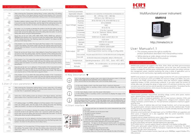
KIM ELECTRIC KMF000 Series User manual

https://kimelectric.kr
KMF000 series
Multi-function power meter
Installation Manual V1.0

KMF000 series
Safety Information
Important Information
Read these instructions carefully and look at the equipment to become familiar with
the device before trying to install, operate, service or maintain it. The following special
messages may appear throughout this bulletin or on the equipment to
wammmmmmrn of potential hazards or to call attention to information that clarifies or
simplifies a procedure.
The addition of either symbol to a “Danger or “Warning safety
label indicates that an electrical hazard exists which will result
in personal injury if the instructions are not followed.
This is the safety alert symbol. It is used to alert you to potential personal
injury hazards. Obey all safety messages that follow this symbol to avoid
possible injury or death.
DANGER
DANGER indicates an imminently hazardous situation which,if not avoided, will result in death or
serious injury.
WARNING
WARNING indicates a potentially hazardous situation which, if not avoided, can result in death
or serious injury.
CAUTION
CAUTION indicates a potentially hazardous situation which, if not avoided, can result in minor or
moderate injury.
NOTICE
NOTICE is used to address practices not related to physical injury. The safety alert symbol shall
not be used with this signal word.
Please Note
Electrical equipment should be installed, operated,serviced, and maintained only by qualified
personnel. No responsibility is asumed by Nova for any consequences arising out of the use of this
material.
A qualified person is one who has skills and knowledge related to the construction, installation,
and operation of electrical equipment and has received safety training to recongnize and avoid the
hazards involved.

KMF000 series
Table of Contents
Chapter 1 Overview .............................................................................................................. - 1 -
1.1. Introduction .................................................................................................................... - 1 -
1.2. Characteristics ............................................................................................................... - 1 -
1.3. Parameters .................................................................................................................... - 2 -
Chapter 2
Technical parameters specification....................................................................... - 3 -
2.1. Specification .................................................................................................................. - 3 -
2.2. Installation dimensions ................................................................................................. - 6 -
2.3. Wiring Diagrams ............................................................................................................ - 6 -
Chapter 3
General function description............................................................................. - 9 -
3.1. Display icon description ................................................................................................ - 9 -
3.1.1. Bar graph for power ............................................................................................... - 9 -
3.1.2. Digital I/O indicating icon ......................................................................................- 10 -
3.2. Multi-tariffs function ......................................................................................................- 10 -
3.3. Demand calculation method ........................................................................................- 10 -
3.3.1. Fixed block interval ...............................................................................................- 10 -
3.3.2. Sliding block interval .............................................................................................- 11 -
3.4. System current direction correction function .............................................................- 11 -
3.5. Description of energy display format ..........................................................................- 12 -
Chapter 4
Operation .............................................................................................................- 12 -
4.1. Power meter startup instructions ................................................................................- 12 -
4.2. LCD display area description ......................................................................................- 13 -
4.3. Button definition description ........................................................................................- 14 -
4.4. Description of display screen ......................................................................................- 14 -
4.4.1. Main display screen ..............................................................................................- 14 -
4.4.2. Auxiliary display screen ........................................................................................- 17 -
4.5. Setting-up......................................................................................................................- 19 -
4.5.1. Set communication class parameters .................................................................- 22 -
4.5.2. Set CT class parameters ......................................................................................- 24 -
4.5.3. Set PT class parameters ......................................................................................- 25 -
4.5.4. Set system class parameters ...............................................................................- 27 -
4.5.5. Set pulse output class parameters ......................................................................- 30 -

KMF000 series
4.5.6. Set demand class parameters .............................................................................- 31 -
4.5.7. Set time class parameters ....................................................................................- 33 -
4.5.8. Reset ......................................................................................................................- 36 -
4.5.9. Set digital input (DI) class parameters ................................................................- 37 -
4.5.10. Set digital output (DO) class parameters ..........................................................- 38 -
4.5.11. Set alarm (AL) class parameters .......................................................................- 40 -
4.5.12. View SOE log information ..................................................................................- 46 -
Chapter 5 Digital input (DI) interface ................................................................................- 47 -
5.1. Function declaration.....................................................................................................- 47 -
5.2. Description of filter function for input detection .........................................................- 47 -
Chapter 6 Digital output (DO) interface............................................................................- 48 -
Chapter 7 Alarm ....................................................................................................................- 49 -
7.1. Alarm parameter description .......................................................................................- 49 -
7.2. Alarm parameter setting process ................................................................................- 50 -
7.3. Rules for alarm monitoring ..........................................................................................- 51 -
7.4. Alarm action process ...................................................................................................- 52 -
7.5. View the alarm event record .......................................................................................- 52 -
Chapter 8
Modbus register address table ........................................................................- 53 -
Appendix .................................................................................................................................- 54 -
Appendix A – LCD character definition table .......................................................................- 54 -
Appendix B – Power meter functional comparison table ....................................................- 54 -
Appendix C – Introduction to the main display screen ........................................................- 55 -
Appendix D – Introduction to auxiliary information display screen ....................................- 59 -

KMF000 series
-
1
-
Chapter 1 Overview
1.1. Introduction
PAC5000 series products are the multi-function power analysis instrument for collection and
analysis of electric parameters, used not only in the electricity transmission and power distribution
system, but also in the power consumption measurement and analysis in high voltage intelligent
power grid. This series of products that can support a variety of electric parameter measurement
analysis, such as voltage, current, the four quadrant power parameters, power factor, total
harmonic distortion, individual harmonic distortion, unbalance factor, crest factor, etc. This series
of products also provide a variety of electrical energy parameters measurement, such as two-way
active energy, reactive energy, four-quadrant energy, monthly and daily energy consumption
statistics.
PAC5000 series products can support in the 1P2W, 2P3W, 3P3W and 3P4W grid environment
analysis of electric power parameter measurement, and at the same time providing multi-channel
digital input/output interface, and SOE function, is suitable for real time power monitoring and
control system, the energy consumption management system, industrial monitoring site using a
variety of applications such as environment, has the multi-function, high stability and long life
characteristics.
PAC5000 series products can support external voltage transformer (PT) and current transformer
(CT) access, the maximum current up to 9999A, the maximum voltage up to 600kV. This series of
products with RS485 communication interface, baud rate maximum support 38400bps, supporting
Modbus, DLT645 communication protocols. It can easily realize the function of remote data read,
and adopt the design of large-screen LCD and touch-sensitive key, which can easily carry out the
local view and set operation of various parameters. The product has the function of password
protection, which ensures the data security of the product.
1.2. Characteristics
Multi-function parameter measurement, providing voltage, current, active power, reactive
power, apparent power, power factor, phase Angle, etc.
Provides a variety of analytical parameters, such as total harmonic distortion (THD) and
Individual harmonic distortion (IHD) of voltage/current, voltage/current unbalance factor,
voltage crest factor, current K factor, etc. The Sub-harmonic component is maximum
supported to the 63rd.
Provide a variety of statistical data and local storage functions, such as two-way power,
four-quadrant power, demand, maximum/minimum value and other statistical data. Provide
monthly electricity consumption statistics for the last 12 months and daily electricity
consumption statistics for the last 31 days.
External current transformers of output types such as 5A/100mV/100mA are supported, and
direct access of Rogowski coil is also supported. With the current transformer reverse
connection correction function.
Support external voltage transformer access, input voltage minimum support 30V.
Embedded installation, product panel size is 96*96mm.
Plug and pull type connection mode, convenient construction connection.

KMF000 series
-
2
-
Liquid crystal display with backlit, backlight lighting time adjustable.
LCD refresh time is 1 second, support manual or automatic scroll display (configurable).
Support multi - channel digital input and output interface.
Two pulse optocoupler output interfaces are pulse 1 and pulse 2 respectively. The output
parameter can be set for pulse 1, while the fixed pulse 2 represents the total active energy of
the secondary side, which cannot be set.
Support RS485 communication function, baud rate up to 38400bps, support Modbus RTU,
MBus protocol.
1.3. Parameters
1 The Unit can measure and display
Instantaneous RMS Values
Current Per phase, neutral
Voltage L-L, L-N
Frequency 45 to 65Hz
Active power Total and per phase
Reactive power Total and per phase
Apparent power Total and per phase
Power factor Total and per phase
Phase sequence Voltage phase sequence, Current phase sequence
Energy Values (include: import, export, import + export)
Active energy 0 to 1.0*10
14
Wh
Reactive energy 0 to 1.0*10
14
varh
Multi-Tariff active energy (T1 - T4) 0 to 1.0*10
14
Wh
Maximum Demand Values
Max.Demand of current Per phase, neutral
Max.Demand of active power Total
Max.Demand of reactive power Total
Max.Demand of apparent power Total
Harmonic Distortion Values
Total harmonic distortion (THD) Current and voltage (L-L and L-N)
Individual harmonic distortion (IHD) Current and voltage (L-L and L-N), 2~63rd
Maximum and Minimum Values
Max./Min.Value of voltage L-L, L-N
Max./Min.Value of current Per phase, neutral
Max./Min.Value of active power Total and per phase
Max./Min.Value of reactive power Total and per phase
Max./Min.Value of apparent power Total and per phase
2 The Unit can measure and communication read
Power Quality Values
Voltage unbalance factor Negative-sequence, Zero-sequence
Current unbalance factor Negative-sequence, Zero-sequence
Voltage crest factor Per phase
Current K factor Per phase
Nature of load System total load, Per phase load

KMF000 series
-
3
-
Displacement power factor Total and per phase
Maximum Demand Values
Max.Demand of active power Import active power, Export active power
The occur time of max. demand Voltage, Current, Active power, Reactive power, Apparent power
Maximum and Minimum Values
Max./Min.Value of current Total current
Max./Min.Value of power factor Total and per phase
Voltage THD L-L, L-N
Current THD Per phase
The occur Time max./min.Value Voltage, Current, Active power, Reactive power, Apparent power,
Power factor, Voltage/Current THD
Energy Values
Apparent Energy (total) 0 to 1.0*10
14
VAh
Per phase energy Active energy and reactive energy, include: import, export, import+export
Range: 0 to 1.0*10
14
Wh/varh
Net energy Active energy and reactive energy. (net = import - export)
Range: 0 to 1.0*10
14
Wh/varh
Multi-Tariff active energy (T1 - T4) Per phase active energy and reactive energy, include: import, export,
import+export
Range: 0 to 1.0*10
14
Wh/varh
Four quadrant reactive energy 0 to 1.0*10
14
varh
Monthly electricity consumption for
the last 12 months
Active energy and reactive energy, include: import, export, import+export
Range: 0 to 1.0*10
14
Wh/varh
Daily energy consumption for the
last 31 days
Active energy, include: import, export, import+export
Range: 0 to 1.0*10
14
Wh
3 The Unit can settable
Communication class Modbus address, baud rate, parity bit, stop bit
Current transformer (CT) class CT1 (Primary), range from 1 to 9999
CT2 (Secondary), range is 1 or 5
Voltage transformer (PT) class PT1 (Primary), range from 30 to 600000
PT2 (Secondary), range is 30 to 600
Power system type 1P2W, 2P3W, 3P3P, 3P4W
System configuration class Current direction correction, User password (HMI)
Demand class Demand interval period, Slide time, Demand calculation method
Pulse output class Pulse output type, Pulse output width, Pulse output rate
Time class Automatic scroll display time, Backlit time, System time (RTC), Tariff time
Reset Energy, Demand, Max./Min.Value, DI count, SOE info
Digital input (DI) class DI filter time, DI count
Digital output (DO) class Output mode, Pulse width time of output, Manual control
Alarm (AL) class Alarm monitoring object, Delay time of alarm action, Alarm threshold value,
Alarm status
Chapter 2
Technical parameters specification
2.1. Specification

KMF000 series
-
4
-
Electrical Characteristics
Type of measurement RMS including harmonics on AC system
128 samples per cycle
Measurement
accuracy
Voltage, Current Class 0.2, according IEC 61557-12
Active power Class 0.5, according IEC 61557-12
Reactive power Class 2, according IEC 61557-12
Apparent power Class 0.5, according IEC 61557-12
Active energy Class 0.5S, according IEC 62053-22
Class 0.5, according IEC 61557-12
Reactive energy Class 2, according IEC 62053-23
Class 2, according IEC 61557-12
Power factor Class 0.5, according IEC 61557-12
Frequency Class 0.05, according IEC 61557-12
Harmonic distortion Class 2, according IEC 61557-12
Data update rate 1 second. Optional 100 ms
Input-Voltage
Rate voltage
(Un)
230 Vac (L-N) / 400 Vac (L-L)
Measured range
(Direct connection)
30 to 350 Vac (L-N), 30 to 660 Vac (L-L)
PT primary 30 to 600000
Impedance 1MΩ
Frequency range 45 to 65 Hz
Overload capacity 2*Un for 1 second
Input-Current
CT2 (Secondary) 1A or 5A
Optional: 100mA, 100mV
CT1 (Primary) 1 to 9999 A
Measured range 0.003 to 6 A, basic current (Ib) is 5A
Impedance <0.01 ohm
Overload capacity 120A for 0.5 second
Burden <0.06VA at 6A
Auxiliary
power supply
Operating range 80 ~ 300 Vac / 100 ~ 420 Vdc
Frequency 45 ~ 65 Hz
Power consumption < 4VA/0.5W
Digital input
(DI)
Number 4
Type Support dry contact input (built-in power supply: 20 ~ 24VDC)
Input Resistance 10kΩ
Maximum frequency 250Hz
Response time 2 milliseconds
Isolation 2.5 kVrms
Digital output
(DO)
Number/Type 2 - electromagnetic relay
Output frequency 10Hz maximum
Switching current 250 Vac at 3.0 Amps, 100k cycles
Isolation 2.5 kVrms
Pulse output
Interface type Open collector optocoupler
Pulse constant Per pulse equal 0.001/0.01/0.1/1/10/100/1000 kWh/kvarh (Configurable)
Pulse width 60/100/200 milliseconds (Configurable), default is 100milliseconds

KMF000 series
-
5
-
Pulse output type Import/export/total active energy,
Import/export/total reactive energy (Configurable)
Class Class A, according IEC 62053-31
Input voltage 5 ~ 27 Vdc
Pulse indicator light on the panel Pulse constant is 5000imp/kWh, Represents the total active energy of
the secondary side
Real-time clock accuracy 1.0 s/d
Mechanical Characteristics
IP Degree of Protection (IEC 60529) Designed to IP51 front display, IP30 meter body
Dimensions (W X H X D) 96 x 96 x 70 mm (depth of meter from housing mounting flange)
96 x 96 x 14 mm (protrusion of meter from housing mounting flange)
Weight PAC5000: 350g. PAC5010: 360g. PAC5100: 390g. PAC5110: 400g.
Mounting Position Vertical
Panel thickness 1 ~ 5 mm
Material of meter case UL 94 V-0
Environmental Characteristics
Operating Temperature -25 to +70
℃
Storage Temperature -40 to +80
℃
Humidity < 90%, non-condensing
Pollution Degree 2
Altitude Up to 2000m
Vibration 10 Hz to 150Hz, IEC 60068-2-6
Electromagnetic Characteristics
Electrostatic Discharge Level 4, according IEC 61000-4-2
(1)
Immunity to Radiated Fields Level 3, according IEC 61000-4-3
(1)
Immunity to Electrical Fast Transients Level 4, according IEC 61000-4-4
(1)
Immunity to Surges Level 4, according IEC 61000-4-5
(1)
Immunity to Conducted Disturbances Level 3, according IEC 61000-4-6
(1)
Immunity to Magnetic Fields IEC 61000-4-8
(1)
Immunity to Voltage Dips IEC 61000-4-11
(1)
Radiated Emissions Class B, according EN55011
Conducted Emissions Class B, according EN55011
Harmonics IEC 61000-3-2
(1)
(1): The experimental test is carried out according to the grade requirements of industrial grade products in
IEC61326-1
Safety
Measurement Category CAT III, according IEC 61010-1
Current Input Require external Current Transformenr for Insulation
Overvoltage Category CAT III, according IEC 61010-1
Insulation AC Voltage Test: 4kV for 1 minute
Impulse Voltage Test: 6kV - 1.2/50µS waveform
Protective Class II, according IEC61010-1
Communications
Interfaces standard and protocols 2-wire RS485, Modbus RTU
Optional: MBus

KMF000 series
-
6
-
Buad rate 1200 to 38400 bps, default is 9600 bps
Parity bit None, Even, Odd, default is None
Stop bit 1 or 2, default is 1
Response time <100ms
Transmission mode half-duplex
Transmission distance Up to 1000m
Max. Bus loading 64 pcs
Firmware Update Support communication port to update firmware
2.2. Installation dimensions
2.3. Wiring Diagrams
Measurement input wiring
3P4W
3CT
3P4W
3PT+3CT

KMF000 series
-
7
-
3P3W
2CT
3P3W
2PT+2CT
3P3W
3CT
2P3W
L+L+N, 2CT
1P2W
L+N
1CT
1P2W
L+L
1CT
1P2W
L+N
3CT

KMF000 series
-
8
-
Auxiliary power wiring
AC Power DC Power
Communication terminal wiring
Single meter wiring Multiple meters wiring
Pulse output terminal wiring
Digital inout and ouput terminal wiring
: 500 mA fast fuse.
: Fast fuse.
In use, the user needs to select the fast fuse according to the load specification parameters.
Terminal specification parameters
Voltage measurement input Wire size: 0.82 ~ 3.31 mm
2
(18 ~ 12 AWG)

KMF000 series
-
9
-
terminal Torque: 0.5 ~ 0.6 N.m
Current measurement input
terminal
Wire size: 1.318 ~ 3.31 mm
2
(16 ~ 12 AWG)
Torque: 0.5 ~ 0.6 N.m
Auxiliary power terminal Wire size: 0.82 ~ 3.31 mm
2
(18 ~ 12 AWG)
Torque: 0.5 ~ 0.6 N.m
Communication terminal Wire size: 0.82 ~ 3.31 mm
2
(18 ~ 12 AWG)
Torque: 0.5 ~ 0.6 N.m
Pulse output terminal Wire size: 0.82 ~ 3.31 mm
2
(18 ~ 12 AWG)
Torque: 0.5 ~ 0.6 N.m
Digital inout and ouput terminal Wire size: 0.82 ~ 3.31 mm
2
(18 ~ 12 AWG)
Torque: 0.5 ~ 0.6 N.m
Chapter 3
General function description
3.1. Display icon description
3.1.1. Bar graph for power
The bar graph for power is used to indicate the percentage of the actual measured value of the
total apparent power value of the power meter to the rated value. The rated value of total apparent
power is equal to the effective phase number * rated voltage value * rated current value.
Figure 3-1: Bar graph for power
Note:
1), Under the measurement type conditions of three-phase four-wire 3CT, three-phase three-wire
3CT and single-phase two-wire 3CT, the effective phase number is equal to 3. Under the
measurement type condition of three phase three-wire 2CT and two phase three-wire 2CT, the
effective phase number is equal to 2.
2), The rated voltage is equal to the rated voltage of the secondary side * the rate of the voltage
transformer.
3), The rated current is equal to the rated current of the secondary side * the rate of the current
transformer.
4), For Example: Under the measurement type conditions of three-phase four-wire 3CT, suppose
the rated voltage of the secondary side is 110V, the rated current of the secondary side is 5A, the
rate of the voltage transformer is 100, and the rate of the current transformer is 40, then the rated
voltage value is 110*100=11kV, and the rated current value is 5*40=200A, so the rated value of the
apparent power is 3*11000*200=6600kVA.
5), Rated voltage of the secondary side defaults to 230V and rated current of the secondary side
defaults to 5A. Both values can be set by communication commands. For specific register
information, please refer to the relevant communication protocol documents of the product.

KMF000 series
-
10
-
3.1.2. Digital I/O indicating icon
The digital I/O indicator icon is used to indicate the status of the digital I/O interface of the current
power meter.
Figure 3-2: Digital I/O indicator icon
If the icon only shows the circle without the dot inside, it means the current state is OFF. If both
circle and dot show, it means the current state is ON. As shown in Figure 3-2, DI-1 and DI-2 are
ON states, DI-3 and DI-4 are OFF states, DO-1 is OFF states and DO-2 is ON states.
3.2. Multi-tariffs function
The multi-tariffs function refers to the function that the meter realizes time-sharing measurement of
electric quantity. The power meter divides the 24 hours of a day into several time periods, and then
specifies the rate number for each time period. Then the power meter accumulates the amount of
electricity in time division according to the pre-divided time period, and stores it to the position of
the rate number corresponding to each time period, so as to realize the function of time-division
measurement of electricity.
The power meter used the method of the tariff number correlation to the starting time point to
realize the tariff segment division. The power meter support up to 8 starting time points and up to 4
tariff segments (T1, T2, T3 and T4).
Figure 3-3: The starting time points of the tariff segment
As shown in Figure 3-3, 06:10 designated as the start time of tariff 1 (T1), 12:00 designated as the
start time of tariff 2 (T2), 18:00 designated as the start time of tariff 3 (T3), 21:00 designated as the
start time of tariff 4 (T4), so tariff 1 time range is 06:10 to 12:00, tariff 2 time range is 12:00 to 18:00,
tariff 3 time range is 18:00 to 21:00, tariff 4 time range is 21:00 to tomorrow 06:10.
Note: The tariff parameters can be set by pressing the button (Refer to step 5 in 4.5.7), also can be
set by communication commands (Please refer to the relevant communication protocol document
for the register address).
3.3. Demand calculation method
3.3.1. Fixed block interval
The block intervals are consecutive, the power meter calilates and updates the demand at the end
of each interval.

KMF000 series
-
11
-
Figure 3-4: Diagram of fixed block interval calculation method
As shown in Figure 3-4, the first demand calculation is made at the 30th minute, and the demand
calculation data is between the 15th and the 30th minute. At the 45th minute, do the second
demand calculation, and the demand calculation data is between the 30th and the 45th minute.
3.3.2. Sliding block interval
The block intervals are sliding, the power meter calculates and update the demand at the sliding
speed.
Figure 3-5: Diagram of sliding block interval calculation method
As shown in Figure 3-5, the first demand calculation is made at the 15th minute, and the demand
calculation data is between the 0th and the 15th minute. At the 16th minute, do the second
demand calculation, and the demand calculation data is between the 1th and the 16th minute. At
the 17th minute, do the third demand calculation, and the demand calculation data is between the
2th and the 17th minute.
3.4. System current direction correction function
This function is to set the wiring direction of the CT of the current channel through internal

KMF000 series
-
12
-
processing of the power meter, without rewiring the CT in this process. In the process of wiring, if
the current transformer is installed in the opposite direction or connected to the power meter in the
opposite direction, the user can use this setting function to ensure that the current measured by
the power meter is in the correct direction without rewiring the current transformer.
Note: This function can be set by pressing the button (Refer to step 3 in 4.5.4), also can be set by
communication commands (Please refer to the relevant communication protocol document for the
register address).
3.5. Description of energy display format
The energy display format of power meter is to automatically adjust the display effective digit
according to the energy value. The change process of effective digit of energy display is shown as
follows:
0.00 kWh/kvarh -> 999999.99 kWh/kvarh -> 1000000.0 kWh/kvarh -> 9999999.9 kWh/kvarh ->
10000000 kWh/kvarh -> 99999999 kWh/kvarh -> 100000.00 MWh/Mvarh -> 999999.99
MWh/Mvarh -> 1000000.0 MWh/Mvarh -> 9999999.9 MWh/Mvarh -> 10000000 MWh/Mvarh ->
99999999 MWh/Mvarh -> 0.00 kWh/kvarh.
Chapter 4
Operation
4.1. Power meter startup instructions
After the PAC5000 series products are properly wired and connected to the power supply, the
products will first enter the self-test process, under which the LCD screen display sequence is
shown as follows:
First screen
display
Display full screen characters
Second
screen
display
Displays the software version
number of the power meter

KMF000 series
-
13
-
Third screen
display
Display the results of the
self-test
4.2. LCD display area description
A: The power grid type icon represents the current measurement type of the power meter.
B: The status indicator icon for the power meter.
C: Bar graph for power indication.
D: Measured values.
E: An icon of a unit of measurement data.
F: Quadrant indicator icon indicating the quadrant of the current load.
G: Multi tariff icon indicating the tariff segment to which the current energy. represents the tariff
number displayed as the running tariff segment.
For example: The figure on the left represents that the tariff 2 (T2) segment is running, and

KMF000 series
-
14
-
the accumulated energy will be counted into the corresponding energy area of tariff 2 (T2).
H: Energy data display area of the power meter.
I: An icon of digital I/O status for the power meter.
J: The battery status icon of the power meter indicates the state of the battery.
4.3. Button definition description
Button Definition Click Press 3 second
Button 1:
Escape key
(Esc)
1. In the setting screen or
auxiliary screen: exit or return to
the previous screen.
2. In the main display screen:
page turning for parameters
such as voltage and current.
Under the main display screen:
enter the auxiliary display
screen.
Button 2:
Up key
(Up)
1. In the main display screen:
view the power factor, maximum
demand.
2. In the setting screen or
auxiliary screen: scroll up to
display the page or the
increasing number.
Null
Button 3:
Down key
(Dn)
1. In the main display screen:
view the power information.
2. In the setting screen or
auxiliary screen: scroll down to
display the page or the
decreasing number.
Null
Button 4:
Enter key
(Et)
1. In the main display screen:
view energy data and system
time.
2. In the setting screen: right
move the setting cursor.
1. In the main display screen:
enter the setting mode.
2. In the auxiliary display
screen: confirm the auxiliary
information to be viewed and
enter the specific display
screen.
3. In the setting screen: enter
the setting state or carry out
confirmation operation.
4.4. Description of display screen
4.4.1. Main display screen
After the power meter is powered on and passes the self-test process, it will enter the main display
screen. This screen is used to display the main measurement parameters and energy data of the
power meter. Users can click the button to turn the page for viewing. Under the main display
screen, the power meter will assign different parameter display for each button according to the
different system types currently set. The logic diagram of display screen controlled by each button

KMF000 series
-
15
-
is shown below. Please refer to Appendix C for the specific display screen diagram.
1. Three-phase four-wire (3P4W)
Note (1): This is only shown if the power meter is a multi tariff model, such as PAC5010 and PAC5110.
2. Three-phase three-wire 2CT (3P3W 2CT)

KMF000 series
-
16
-
Note (1): This is only shown if the power meter is a multi tariff model, such as PAC5010 and PAC5110.
3. Three-phase three-wire 3CT (3P3W 3CT)
Note (1): This is only shown if the power meter is a multi tariff model, such as PAC5010 and PAC5110.
4. Single-phase two-wire (1P2W)
Note: In single-phase two-line mode, the measurement voltage input end is connected to the
same voltage line, and the current input end can be connected to three current transformers to
measure three different single-phase loads. Therefore, the product can be used as a product with
a 3-channel measurement loop.
Note (1): This is only shown if the power meter is a multi tariff model, such as PAC5010 and PAC5110.
Table of contents
Other KIM ELECTRIC Measuring Instrument manuals