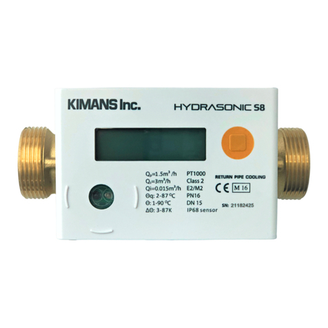
Kimans HYDRASONIC S8 User manual

HYDRASONIC S8 FLANGED
ULTRASONIC HEATING/COOLING METER
Attention:
•Installation should only be carried out by qualified, trained personnel
•Violation and removal of the manufacturer's seals is not allowed, otherwise the warranties are void
•Welding on pipes near the meter is prohibited. The device must be dismounted before welding
•Eliminate the possibility of flooding the electronic unit
•The ambient temperature should be between 0 °C and 55 °C
User Manual

Table of content
1. General Information...................................................................................................................................................3
1.1 Application and Function.......................................................................................................................................3
1.2 Contents of the package ........................................................................................................................................3
1.3 Standards ..................................................................................................................................................................3
2. Installation procedure...............................................................................................................................................4
2.1 Installation of the meter ........................................................................................................................................4
2.2 Installation angle .....................................................................................................................................................5
2.3 Straight inlet .............................................................................................................................................................5
2.4 Installation of temperature sensors ...................................................................................................................6
2.5 Temperature sensor pocket installation............................................................................................................6
3. Installation procedure...............................................................................................................................................7
4. Lay length of BTU meter ...........................................................................................................................................7
5. Display Menu ...............................................................................................................................................................8
5.1 Overall Menu Structure...........................................................................................................................................9
5.2 Main Display............................................................................................................................................................10
5.3 Test Display.............................................................................................................................................................11
5.4 Information Display...............................................................................................................................................12
5.5 Error Display ...........................................................................................................................................................13

1. General Information
1.1 Application and Function
This Hydrasonic S8 is designed for the measurement of consumed energy in a closed heating, cooling or heating
/cooling system.
1.2 Contents of the package
•Heat meter or heat/cooling meter, consisting of a calculator, a flow sensor and two temperatures
sensors, all permanently connected to each other
•Installation kit (depending on type)
•Installation and Operating Instructions
•Operating Instructions, Communication Interfaces S3(C) (with meters with an optional interface)
•Declaration of Conformity
1.3 Standards
•Valid standards for the application of heat meters: EN 1434, parts 1 –6; the Measuring instruments
•Directive 2014/32/EU, Annexes I and MI-004; and the relevant national verification regulations.
•For the selection, installation, commissioning, monitoring and maintenance of the instrument observe
the standard EN 1434 part 6, as well as the verification regulations PTB TR K8 + K9 for Germany (and any
relevant national verification regulations in other countries).
•National regulations for the consumption measurement of cooling must be observed.
•The technical regulations for electrical installations must be observed.
•This product fulfils the requirements of the European Council Directive on Electromagnetic Compatibility
(EMC Directive) 2014/30/EU.
•The identification plate of the instrument and the seals must not be removed or damaged otherwise the
guarantee and the approved application of the instrument are no longer valid!
•To achieve measurement stability of the meter it is necessary that the water quality meets the
requirements of the AGFW-recommendation FW-510 and the document VDI (Association of German
Engineers) VDI 2035.
•The heat meter left the factory in conformance with all applicable safety regulations. All maintenance
and repair work are to be carried out only by qualified and authorized technical personnel.
•Instruments with activated radio function are not allowed on air freight.
•The correct installation point in the system must be chosen: inlet or outlet flow.
•The temperature sensor cables and the cable between the calculator and flow sensor must not be
kinked, rolled up, lengthened or shortened.
•To clean the heat meter (only if necessary) use a slightly moist cloth.
•To protect against damage and dirt the heat meter should only be removed from the packaging directly
before installation.
•If more than one heat meter is installed in one unit, care must be taken to ensure that all meters have
the same installation conditions.
•All specifications and instructions listed on the data sheet and in the application notes must be adhered,
further information can be obtained at www.kimans.com

•The heat meter has a lithium-metal-battery. Do not open the batteries, do not bring the batteries into
contact with water or expose them to temperatures above 80 °C. Do not charge them or short-circuit
them.
•Instruments which have been replaced or exchanged must be disposed of according to relevant
environmental regulations.
2. Installation procedure
2.1 Installation of the meter
•Check section 4 for meter lay length.
•Install a spool piece at installation location that is equal to or larger than the meter lay length
determined.
•Flush the pipes professionally, taking care not to damage any system components.
•Close the isolation valves at installation location.
•Open the nearest draining valve for pressure release.
•Drain the spool piece pipe section.
•Use gaskets between mating flanges on pipe and meter.
•The meter can be installed in supply or return flow lines. Please consult with factory on ordering to
program the meter for either the supply or return installation positions. During installation, pay
attention to the flow direction of medium is as the same as the arrow on the heat meter pipe body.
Special Note: regardless if meter installed on supply pipe or return flow pipe, the temperature sensor should
be properly connected (red label for return pipe, blue label for supply pipe).
•It is recommended to install a filter before the inlet of the meter, and to be cleaned and maintained
regularly.
Large diameter
heat meter
Pressure sensor
The length of straight pipe is 10
times longer than that of meter
tube
The length of
straight pipe is 5
times longer than
that of meter
tube
Inflow temperature sensor
Valve
Valve
Return flow temperature sensor
Inflow
Filter
Return flow

2.2 Installation angle
The meter can be installed horizontally, vertically, or at an angle.
The meter is normally installed horizontally, the lifting rings being vertically oriented. The ultrasound paths in
the flow sensor tube will thus be vertical, which is optimal in connection with possible stratification of the
medium.
2.3 Straight inlet
Kimans flanged meter requires neither straight inlet nor outlet in order to fulfill the measuring instruments
directive (MID) 2014/32/EU and EN 1434:2015. Only in case of heavy flow disturbances before the meter will a
straight inlet section be necessary. We recommend following the guidelines in CEN CR 13582.
Optimal position can be obtained by taking the below-mentioned installation methods into consideration.
A. Recommended meter position.
B. Recommended meter position.
C. Unacceptable position due to risk of air build-up.
D. Acceptable position in closed systems. Unacceptable position in open systems due to risk of air build-up
in the system.
E. Meter not to be placed immediately after a valve, with the exception of isolation valves which must be
fully open when it’s not used for blocking.
F. Meter not to be placed directly before (inlet side) or directly after (outlet side) of a pump.
G. Meter not to be placed directly after a double bend, in two levels.

2.4 Installation of temperature sensors
•The meter is operated with separately approved pairs of Pt 1000 temperature sensors.
•Ensure that the approved temperature range of the temperature sensors is the same as the temperature
range of the calculator.
•Handle the temperature sensors carefully.
•The sensor cables are fitted with colored type labels:
oBlue: sensor in cold line
oRed: sensor in hot line
•The temperature sensors are to be installed symmetrically in the supply and return line.
•The free temperature sensor can be installed in a pocket conforming to the requirements for this type
of sensor.
2.5 Temperature sensor pocket installation
The pockets are best installed in T-pieces with a 45 ° or 90 °angle. The tip of the pocket must point in the opposite
direction to the direction of flow and must be located in the middle of the pipe, the temperature sensors must
be sealed after installation in the pockets.

3. Installation procedure
The meter can be put in operation once it has been installed.
Proceed as follows:
•After the installation of the BTU meter, open the isolation valves, and allow the water to pass inside the
meter.
•Check the system for leaks.
•Check the display for flow rate and temperature.
•Seal the sensors.
•Attach the seals to the calculator and temperature sensors.
•Read the meter counts for energy, volume and operating hours.
•Ensure no errors are displayed on the LCD
4. Lay length of BTU meter
Diameter
Length (L)
Height (mm)
Width (mm)
Stud Bolt
Bolt holes
DN50
200
175.55
143
M16
4
DN65
200
187.55
150
M16
4
DN80
225
211.55
184.2
M16
8
DN100
250
227.55
200
M16
8
DN125
250
248.55
230
M16
8

5. Display Menu
The calculator has a liquid crystal display with 8 digits and special characters. The values that can be shown are
divided into five display loops. All data is retrieved using the push-button next to the display.
At the start you are automatically in the main loop (1st level).
By pressing the push-button longer than 4 seconds you change to the next display loop. Keep the push- button
pressed until you reach the desired information loop.
By pressing the push-button briefly each time you can scan all the information within a loop. After 2 minutes of
non-use of the push-button, the display will automatically be deactivated.
[Ref. next page]

5.1 Overall Menu Structure

5.2 Main Display
Short press < 3 sec
Long press > 3 sec

5.3 Test Display

5.4 Information Display

5.5 Error Display

Kimans Inc.
www.kimans.com
Other manuals for HYDRASONIC S8
1
Table of contents
Other Kimans Measuring Instrument manuals