Kimray BK2900 Series Owner's manual

LIQUID FLOW METER MONITOR
BK2900

Compact Digital Flow Monitor, Model BK2900
Page ii March 2016

User Manual
Page iiiMarch 2016
CONTENTS
Introduction. . . . . . . . . . . . . . . . . . . . . . . . . . . . . . . . . . . . . . . . . . . . . . . . . . . . . . . . . . . . . . . . . . . . . . . . . 5
Scope of This Manual . . . . . . . . . . . . . . . . . . . . . . . . . . . . . . . . . . . . . . . . . . . . . . . . . . . . . . . . . . . . . . . . . . . 6
Unpacking and Inspection . . . . . . . . . . . . . . . . . . . . . . . . . . . . . . . . . . . . . . . . . . . . . . . . . . . . . . . . . . . . . . . 6
Safety . . . . . . . . . . . . . . . . . . . . . . . . . . . . . . . . . . . . . . . . . . . . . . . . . . . . . . . . . . . . . . . . . . . . . . . . . . . . . 6
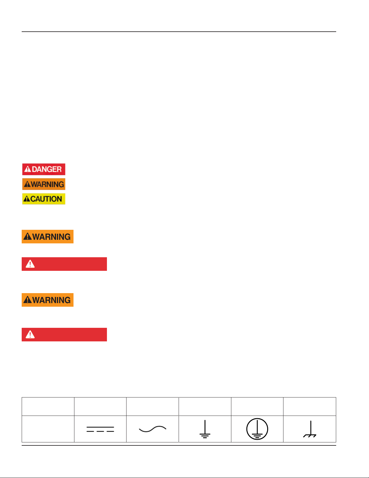
Terminology and Symbols . . . . . . . . . . . . . . . . . . . . . . . . . . . . . . . . . . . . . . . . . . . . . . . . . . . . . . . . . . . . . 6
Considerations . . . . . . . . . . . . . . . . . . . . . . . . . . . . . . . . . . . . . . . . . . . . . . . . . . . . . . . . . . . . . . . . . . . . 6
Electrical Symbols . . . . . . . . . . . . . . . . . . . . . . . . . . . . . . . . . . . . . . . . . . . . . . . . . . . . . . . . . . . . . . . . . . 6
Installation. . . . . . . . . . . . . . . . . . . . . . . . . . . . . . . . . . . . . . . . . . . . . . . . . . . . . . . . . . . . . . . . . . . . . . . . . . 7
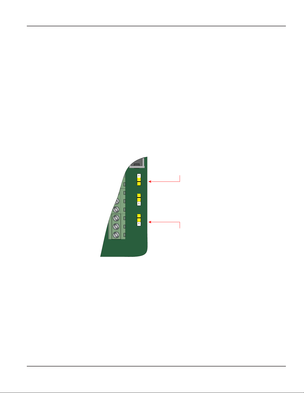
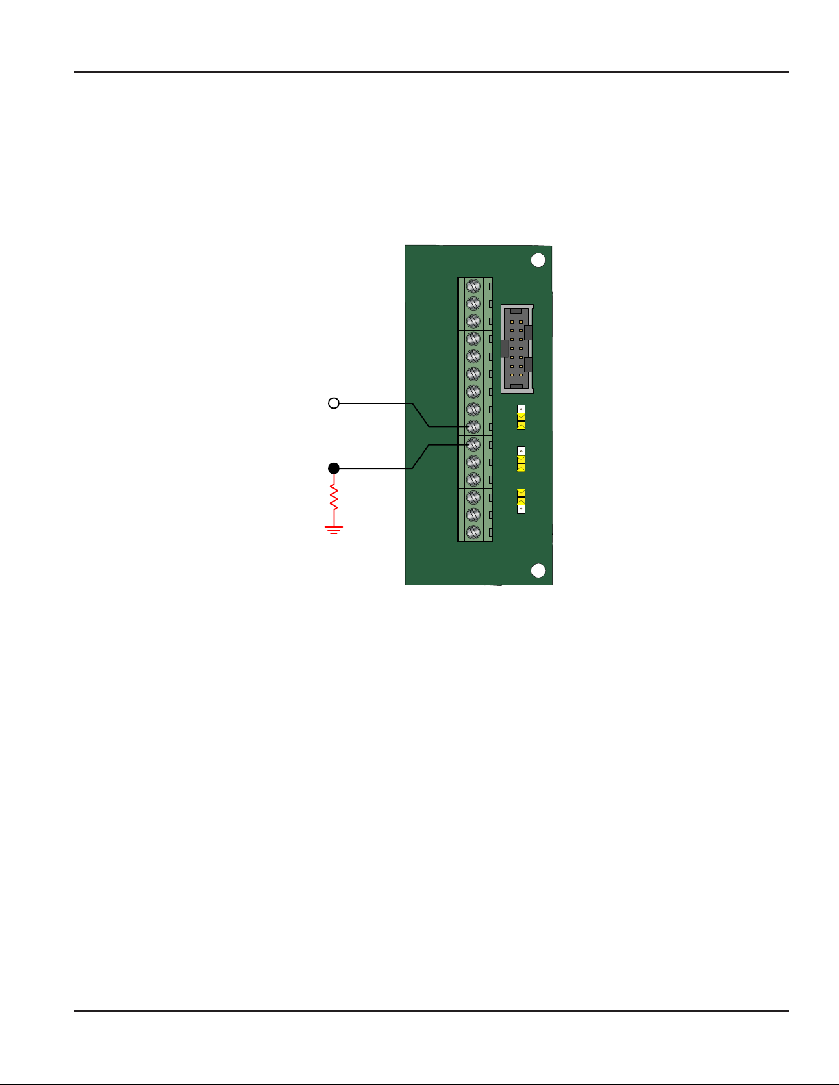
Connecting the BK2900 Monitor to a Frequency Output Device . . . . . . . . . . . . . . . . . . . . . . . . . . . . . . . . . . . . . 7
Power Connections . . . . . . . . . . . . . . . . . . . . . . . . . . . . . . . . . . . . . . . . . . . . . . . . . . . . . . . . . . . . . . . . . . . . 9
Standard . . . . . . . . . . . . . . . . . . . . . . . . . . . . . . . . . . . . . . . . . . . . . . . . . . . . . . . . . . . . . . . . . . . . . . . . 9
Operating The Monitor . . . . . . . . . . . . . . . . . . . . . . . . . . . . . . . . . . . . . . . . . . . . . . . . . . . . . . . . . . . . . . . . . 10
Buttons . . . . . . . . . . . . . . . . . . . . . . . . . . . . . . . . . . . . . . . . . . . . . . . . . . . . . . . . . . . . . . . . . . . . . . . . 10
Modes of Operation . . . . . . . . . . . . . . . . . . . . . . . . . . . . . . . . . . . . . . . . . . . . . . . . . . . . . . . . . . . . . . . . 11
Programming Using Frequency Output Turbine Flow Meters. . . . . . . . . . . . . . . . . . . . . . . . . . . . . . . . . . . . . . 11
Enter Programming Mode . . . . . . . . . . . . . . . . . . . . . . . . . . . . . . . . . . . . . . . . . . . . . . . . . . . . . . . . . . . . 11
Programming . . . . . . . . . . . . . . . . . . . . . . . . . . . . . . . . . . . . . . . . . . . . . . . . . . . . . . . . . . . . . . . . . . . . . . . 12
Liquid . . . . . . . . . . . . . . . . . . . . . . . . . . . . . . . . . . . . . . . . . . . . . . . . . . . . . . . . . . . . . . . . . . . . . . . . . 12
Gas. . . . . . . . . . . . . . . . . . . . . . . . . . . . . . . . . . . . . . . . . . . . . . . . . . . . . . . . . . . . . . . . . . . . . . . . . . . 21
Return to Run Mode . . . . . . . . . . . . . . . . . . . . . . . . . . . . . . . . . . . . . . . . . . . . . . . . . . . . . . . . . . . . . . . . 21
Troubleshooting Guide. . . . . . . . . . . . . . . . . . . . . . . . . . . . . . . . . . . . . . . . . . . . . . . . . . . . . . . . . . . . . . . . . 22
Default K-Factor Values . . . . . . . . . . . . . . . . . . . . . . . . . . . . . . . . . . . . . . . . . . . . . . . . . . . . . . . . . . . . . . . . . 22
Battery Replacement . . . . . . . . . . . . . . . . . . . . . . . . . . . . . . . . . . . . . . . . . . . . . . . . . . . . . . . . . . . . . . . . . . 23
Menu Maps . . . . . . . . . . . . . . . . . . . . . . . . . . . . . . . . . . . . . . . . . . . . . . . . . . . . . . . . . . . . . . . . . . . . . . . . 24
K-Factors Explained . . . . . . . . . . . . . . . . . . . . . . . . . . . . . . . . . . . . . . . . . . . . . . . . . . . . . . . . . . . . . . . . . . . 28
Calculating K-factors . . . . . . . . . . . . . . . . . . . . . . . . . . . . . . . . . . . . . . . . . . . . . . . . . . . . . . . . . . . . . . . 28
Modbus Interface . . . . . . . . . . . . . . . . . . . . . . . . . . . . . . . . . . . . . . . . . . . . . . . . . . . . . . . . . . . . . . . . . . . . 31
Modbus Register / Word Ordering . . . . . . . . . . . . . . . . . . . . . . . . . . . . . . . . . . . . . . . . . . . . . . . . . . . . . . . 32
Specications . . . . . . . . . . . . . . . . . . . . . . . . . . . . . . . . . . . . . . . . . . . . . . . . . . . . . . . . . . . . . . . . . . . . . . . 34
Mounting Options and Dimensions. . . . . . . . . . . . . . . . . . . . . . . . . . . . . . . . . . . . . . . . . . . . . . . . . . . . . . . . . 36
Meter Mount . . . . . . . . . . . . . . . . . . . . . . . . . . . . . . . . . . . . . . . . . . . . . . . . . . . . . . . . . . . . . . . . . . . . 36
Remote Mount . . . . . . . . . . . . . . . . . . . . . . . . . . . . . . . . . . . . . . . . . . . . . . . . . . . . . . . . . . . . . . . . . . . 36
Swivel Mount . . . . . . . . . . . . . . . . . . . . . . . . . . . . . . . . . . . . . . . . . . . . . . . . . . . . . . . . . . . . . . . . . . . . 37

Compact Digital Flow Monitor, Model BK2900
Page iv March 2016

Introduction
Page 5March 2016
INTRODUCTION
The BK2900 flow monitor incorporates state-of-the-art, digital signal processing technology, designed to provide exceptional
flexibility at a very affordable price. Though designed for use with Kimray flow sensors, this monitor can be used with almost
any flow sensor producing a low amplitude AC output or contact closure signal.
This monitor can accept low-level frequency input signals typically found in turbine flow
sensors. The output signal for these types of sensors is a frequency proportional to the rate of flow. The BK2900 monitor uses
the frequency information to calculate flow rate and total flow. Through the use of the programming buttons, you can select
rate units, total units and unit time intervals among other functions. All BK2900 flow monitors come pre-configured from the
factory, when ordered with a Kimray flow sensor. If required, the monitor can easily be re-configured in the field. Finally, you
can choose between simultaneously showing rate and total, or alternating between rate and grand total.
The package is a polycarbonate NEMA 4X enclosure.
BK2900 SERIES FLOW MONITORING SYSTEM
TOTAL FLOW RESET
405-525-6601 www.kimray.com
Kimray BK2900 Keypad.pdf 1 3/9/16 4:48 PM
Figure 24: BK2900 Flow monitor (NEMA 4X)

Scope of This Manual
Page 6 March 2016
SCOPE OF THIS MANUAL
This manual is intended to help you get the BK2900 flow monitor up and running quickly.
MPORTANTI
Read this manual carefully before attempting any installation or operation. Keep the manual accessible for future reference.
UNPACKING AND INSPECTION
Upon opening the shipping container, visually inspect the product and applicable accessories for any physical damage such
as scratches, loose or broken parts, or any other sign of damage that may have occurred during shipment.
OTE:N If damage is found, request an inspection by the carrier’s agent within 48 hours of delivery and file a claim with the
carrier. A claim for equipment damage in transit is the sole responsibility of the purchaser.
SAFETY
Terminology and Symbols
Indicates a hazardous situation, which, if not avoided, is estimated to be capable of causing death or
serious personal injury.
Indicates a hazardous situation, which, if not avoided, could result in severe personal injury or death.
Indicates a hazardous situation, which, if not avoided, is estimated to be capable of causing minor or
moderate personal injury or damage to property.
Considerations
The installation of the BK2900 monitor must comply with all applicable federal, state, and local rules, regulations, and codes.
EXPLOSION HAZARD - SUBSTITUTION OF COMPONENTS MAY IMPAIR SUITABILITY FOR CLASS I, DIVISION 2.
AVERTISSMENT
RISQUE D’EXPLOSION - LA SUBSTITUTION DE COMPOSANTS PEUT RENDRE CEMATÉRIEL INACCCEPTABLE POUR LES
EMPLACEMENTS DE CLASSE I, DIVISION 2.
DO NOT CONNECT OR DISCONNECT EITHER POWER OR OUTPUTS UNLESS THE AREA IS KNOWN TO BE NON-
HAZARDOUS.
AVERTISSMENT
RISQUE D’EXPLOSION. NE PAS DÉBRANCHER TANT QUE LE CIRCUIT EST SOUSTENSION, À MOINS QU’LL NE S’AGISSE
D’UN EMPLACEMENT NON DANGEREUX.
MPORTANTI
Not following instructions properly may impair safety of equipment and/or personnel.
Electrical Symbols
Function Direct
Current
Alternating
Current
Earth
(Ground)
Protective
Ground
Chassis
Ground
Symbol

Installation
Page 7March 2016
INSTALLATION
Connecting the BK2900 Monitor to a Frequency Output Device
The BK2900 monitor has two jumpers for setting the type of signal and the minimum amplitude of the signal that it accepts.
First, establish the type of output provided by the flow sensor. The outputs almost always fall into one of two types.
• Type 1 is the unaltered frequency signal coming from an un-amplified magnetic pickup. This signal is normally a sine wave
in appearance, and the amplitude of the waveform varies with the flow. Small turbines have comparatively small rotating
masses so they produce a smaller amplitude waveform and higher frequencies than larger turbine sensors.
• Type 2 is the frequency signal from the transducer is amplified, wave shaped or both to produce a waveform of a specified
type and amplitude. Most amplified transducers output a square wave shape at one of many standard amplitudes. For
example, a popular amplified output is a 10V DC square wave.
If the flow sensors output signal is type 1, you must also determine the minimum amplitude of the frequency output. The
BK2900 monitor has a high or low signal sensitivity setting. Use the high signal sensitivity (30 mV) with low amplitude (usually
small) turbine flow sensors. Use the low signal sensitivity setting (60 mV) for larger turbines and amplified transducers (see
Figure 2).
OTE:N Use the high signal sensitivity setting where the minimum signal amplitude is below 60 mV. Setting the sensitivity
higher than necessary may allow noise interference.
JP1
JP2
JP3
Input Total Pulse Signal
TB1
Mag
Pulse
Iso
OC
Low
High
Input Waveform Selection
(Magnetic Pickup Selection Shown)
Input Signal Level Selection
(Low Signal Sensitivity (60 mV) Selection Shown)
Figure 1: Input jumper settings (NEMA 4X)
When the type of waveform and input signal level (amplitude) are determined, set the jumpers on the BK2900 monitor
circuit board.
For typical variable reluctance magnetic pickups, set the waveform selection jumper for Mag. Determine the setting for the
input level by looking at the magnetic pickup specifications. If the minimum amplitude at the minimum rated flow is greater
than 60 mV, use the low signal sensitivity jumper position (see Figure 2).
If the minimum signal level is below 60 mV, use the high signal sensitivity jumper position.

Installation
Page 8 March 2016
JP1
JP2
JP3
Input Total Pulse Signal
P1
Freq. In
4-20mA
Iso TotalPluse
RS485 B (–)
RS485 A (+)
RS485 Gnd
Setpoint 1
Setpoint 2
Gnd
+
–
+
–
+
–
TotalReset
OC TotalPluse
Signal Gnd
TB1
Mag
Pulse
Iso
OC
Low
High
Mag
Pulse
JP1
Input
Figure 2: Typical magnetic pickup connection (NEMA 4X)
For amplified input signals, set the input jumper to Pulse and the signal jumper to Low (see Figure 4).
OTE:N Amplified magnetic pickups require an external power source. The BK2900 monitor does not supply power to an
amplified pickup.
JP1
JP2
JP3
Input Total Pulse Signal
P1
Freq. In
4-20mA
Iso TotalPluse
RS485 Gnd
Setpoint 1
Setpoint 2
Gnd
+
–
+
–
+
–
TotalReset
OC TotalPluse
Signal Gnd
TB1
Mag
Pulse
Iso
OC
Low
High
POWER
SUPPLY
Mag
Pulse
JP1
Input
RS485 B (–)
RS485 A (+)
Figure 3: Typical amplified pickup connection (NEMA 4X)

Power Connections
Page 9March 2016
POWER CONNECTIONS
Standard
The power supply used in the BK2900 monitor is an internal lithium 3.6V DC D cell that powers the monitor for about six years
when no outputs are used. The monitor can also get power from a 4…20 mA current loop (see Figure 5). If the current loop is
used, a sensing circuit within the monitor detects the presence of the current loop and disconnects the battery from
the circuit.
JP1
JP2
JP3
Input Total Pulse Signal
P1
Freq. In
4-20mA
Iso Total Pluse
RS485 Gnd
Setpoint 1
Setpoint 2
Gnd
+
–
+
–
+
–
Total Reset
OC Total Pluse
Signal Gnd
TB1
Mag
Pulse
Iso
OC
Low
High
4…20 mA
Current Loop
(10…28V DC)
Load
10…28V DC
RS485 B (–)
RS485 A (+)
Figure 4: Loop power connections (NEMA 4X)

Operating The Monitor
Page 10 March 2016
OPERATING THE MONITOR
Buttons
BK2900 SERIES FLOW MONITORING SYSTEM
TOTAL FLOW RESET
405-525-6601 www.kimray.com
Kimray BK2900 Keypad.pdf 1 3/9/16 4:48 PM
Figure 5: Keypad detail
MENU Switches to PROGRAM mode, press and hold for three seconds to enter EXTENDED
PROGRAMMING mode, and is used in reset process
UP Scrolls forward through the parameter choices, increments numeric variables and
increases display contrast in RUN mode
RIGHT Scrolls backward through the parameter choices, moves the active digit to the right and
decreases display contrast in RUN mode
ENTER Saves programming information, advances to the next programming parameter, and is
used in the reset process
Special Functions
MENU + ENTER Simultaneously press and hold to reset the current totalizer
UP + RIGHT Simultaneously press and hold to show the firmware version number, then the grand total

Operating The Monitor
Page 11March 2016
Modes of Operation
The monitor has three modes of operation— Run, Programming and Extended Programming modes.
2
1Battery
Indicator
Alarm
Activation
Rate
Units
Totalizer
Units
Totalizer
Multiplier
Total
Rate
Communications
Indicator
Figure 6: Display annunciators
RUN Normal operating mode
PROGRAM Program variables into the display
EXTENDED PROGRAM Program advanced variables into the display
TEST Diagnostic tool to show input frequency and totalizer counts
If your monitor was ordered with a Kimray flow meter, the two components ship from the factory configured as a set. If the
monitor is a replacement, the turbine’s K-factor changed or the monitor is used with some other pulse generating device, you
must program it.
Programming Using Frequency Output Turbine Flow Meters
Each Kimray turbine flow meter is shipped with either a K-factor value or frequency data. If frequency data is provided, the
data must be converted to a K-factor before programming the monitor. K-factor information, when supplied, can usually be
found on the neck of the flow meter or stamped on the flow meter body. The K-factor represents the number of pulses per
unit of volume (see K-Factors Explained on page 28). The K-factor is required to program the monitor.
Enter Programming Mode
To access the Programming mode, momentarily press and then release MENU. The monitor displays Fluid. To access the
Extended Programming mode, press and hold MENU until Fluid is displayed. To return to Run mode, press MENU.
2
1Battery
Indicator
Units
Indicator
Totalizer
Units
Totalizer
Multiplier
Numeric
Values
Function
Figure 7: Programming mode display

Programming
Page 12 March 2016
PROGRAMMING
The following programming assumes the meter is set for liquid. Parameters for gaseous fluids can be found in
Gas on page 21.
OTE:N All of the following parameters appear in Extended Programming mode. Parameters with an asterisk (*) appear in
Programming mode as well.
Liquid
Select Fluid*
At the Fluid prompt, press ENTER to view the current fluid type. If the current fluid type is correct, press ENTER to advance to
the next parameter. To change the fluid type, press UP or RIGHT to switch between Liquid or Gas. Press ENTER to save and
advance to the Meter parameter.
OTE:N The fluid selection choice affects which menu choices are available. See Menu Maps on page 24 for details.
Select Meter Size*
At the Meter prompt, press ENTER to display the current meter size. If the current meter size is correct, press ENTER to
advance to the next parameter. To change the meter size, press UP or RIGHT to scroll to the correct meter size. Press ENTER to
advance to the next parameter.
OTE:N The meter size selection refers to the bore of the meter and not the connections size. For a listing of the Kimray
turbine bore sizes, see the default K-factor table in Default K-Factor Values on page 22.
OTE:N In Programming mode, the monitor advances to the KFacUnit parameter.
See Select Meter’s K-Factor Unit* on page 13.
Select Display Function
The BK2900 monitor has three display settings, Flow, Grand Total and Test.
Flow
Use the Flow setting for normal operation of the monitor. In this mode, the display shows both the instantaneous flow rate
and current total simultaneously. See Figure 9.
2
1
Current Total Units
Flow Rate
Units
Totalizer
Multiplier
Current
Total
Instantaneous
Flow Rate
Figure 8: Instantaneous flow rate and current total

Programming
Page 13March 2016
Grand Total
The Flow-GT setting forces the meter to alternate between the instantaneous flow and the grand total with roll-over counts.
See Figure 10.
The grand total is the accumulation of all the fluid that has gone through the meter since the last time the grand total was
cleared. This totalizer is in addition to the current total totalizer on the display and is always enabled.
In addition, the grand total screen displays the number of times the grand total has reached its maximum count (9,999,999)
and rolled over to zero.
2
1
Roll-Over
Indicator
Totalizer
Mode
Total
Roll-Overs
Figure 9: Grand total
Test
The Test setting places the monitor into a special diagnostic mode that shows the current input frequency and the
accumulated input counts. Figure 11 shows the layout for test mode values. The Test mode makes it possible for you to see the
frequency input the monitor is measuring and is very useful in troubleshooting and noise detection.
2
1
Input
Frequency
Totalizer
Counts
Figure 10: Test mode screen
At the Display prompt, press ENTER to view the current display setting. If the current display setting is correct, press ENTER to
advance to the next parameter. To change the display setting, press UP or RIGHT to scroll through the display options. Press
ENTER to save and advance to the KFacUnit parameter.
Select Meter’s K-Factor Unit*
At the KFacUnt prompt, press ENTER. The display shows the current K-factor unit. If the current selection is correct, press
ENTER to advance to the next parameter. To change the K-factor unit, press UP or RIGHT to scroll to the correct unit, the units
should match the units that the meter was calibrated in. Press ENTER to save and advance to the KFactor parameter.
Enter Meter’s K-Factor*
OTE:N The K-factor supplied with your meter, or calculated from calibration data, is needed to complete this step.
At the KFactor prompt, press ENTER. The most significant digit in the K-factor flashes. If the current K-factor is correct, press
ENTER to advance to the next parameter. To change the K-factor, press UP to increment the digit until it matches the meter’s
first K-factor digit. Press RIGHT to advance to the next digit. Repeat this process until all K-factor digits have been entered.
Press ENTER to save the K-factor and advance to the RateInt parameter.
OTE:N The number of digits available before and after the decimal point is determined by the bore size of the flow sensor
being used. The largest K-factors are associated with the smallest bore sizes. The maximum allowable K-factor is
99999.9. The minimum must be at least 1.000. If an out of range number is entered, the display flashes Limit and
refuses the entry.

Programming
Page 14 March 2016
Select Rate Interval*
At the RateInt prompt, press ENTER. The monitor flashes the current time interval. If the current selection is correct, press
ENTER to advance to the next parameter. To change to an alternate time interval, press UP or RIGHT to scroll to the required
time interval. Press ENTER to save and advance to the RateUnt parameter.
Select Flow Rate Units*
At the RateUnt prompt, press ENTER. The monitor flashes the current rate unit. If the current selection is correct, press ENTER
to advance to the next parameter. To change to an alternate unit, press UP or RIGHT to scroll to the required rate unit and
press ENTER to save and advance to the TotlUnt parameter.
Select Total Units of Measure*
At the TotlUnt prompt, press ENTER. The monitor flashes the current total units. If the current selection is correct, press ENTER
to advance to the next parameter. To change to an alternate unit, press UP or RIGHT to scroll to the required totalization unit.
Press ENTER to save and advance to the TotlMul parameter.
Select Total Multiplier*
This parameter displays the accumulated flow total in multiples of 10. For example, if the optimum totalization unit is 1000
gallons, the unit total display increments by one digit for every 1000 gallons monitored. In Run mode, at 1000 gallons the total
monitor reads 1, at 3000 gallons, the total display reads 3. This feature eliminates having to look at a total, count the digits,
and mentally insert commas for each 1000 multiple.
At the TotlMul prompt, press ENTER . The monitor shows the current total multiplier. If the selection is correct, press ENTER to
advance to the next parameter. To change to an alternate multiplier, press UP or RIGHT to scroll to the required multiplier unit
and press ENTER to and advance to the next parameter.
OTE:N If the RateUnt or TotlUnt parameter has been set to pounds or kilograms, the monitor advances to the Spec Gr
parameter. At any other setting, the monitor advances to PulsOut in Programming mode. See Totalizer Pulse Output*
on page 16.
Enter Specific Gravity Value*
Mass readings in the BK2900 monitor are not temperature or pressure compensated so it is best to enter the specific gravity
of the fluid as close to the system running temperature as possible. As liquids are essentially incompressible, pressure
compensation is not necessary for liquids.
At the Spec Gr prompt, press ENTER. The most significant digit of the current specific gravity flashes. If the current specific
gravity is correct, press ENTER to advance to the next parameter. To change to an alternate specific gravity, press UP to
increment the flashing digit until you reach the first digit of the new specific gravity. Press RIGHT to move to the next digit.
When all digits have been entered, press ENTER to save and advance to the next parameter.
OTE:N If Gas was chosen as the fluid, see Gas on page 21 and follow the directions for the gas parameters.
In Programming mode, the monitor advances to the PulsOut parameter, see Totalizer Pulse Output* on page 16.
Enter a Scale Factor
The scale factor is used to force a global span change. For example, in Run mode the display is reading a consistent three
percent below the expected values at all flow rates. Rather than changing the K-factor and linearization parameters
individually, the scale factor can be set to 1.03 to correct the readings. The range of scale factors is from 0.10…5.00. The
default scale factor is 1.00.
At the Scale F prompt, press ENTER. The first digit of the existing scale factor flashes. If the current selection is correct, press
ENTER to advance to the next parameter. To change to an alternate scale factor, press UP to increment the display digit until
it matches the first digit of the new scale factor. Press RIGHT to advance to the next digit. Repeat for all digits. Press ENTER to
save and advance to the SetTotl parameter.
OTE:N If the number you enter is out of range, the display flashes Limit and refuses the entry.

Programming
Page 15March 2016
Preset Total
The preset total parameter sets the totalizer to a predetermined amount. The preset can have seven digits up to 8,888,888.
At the SetTotl prompt, press ENTER. The monitor displays the current set total. If the set total is correct, press RIGHT to
advance to the next parameter. To change the set total, press ENTER again. The first digit of the current preset total flashes.
Press UP to increment the display digit until it matches the first digit of the correct preset. Press RIGHT to advance to the next
digit. Repeat for all digits. Press ENTER to save and advance to the Cutoff parameter.
OTE:N If the number you enter is out of range, the display flashes Limit and refuses the entry.
Low Flow Cutoff
The flow cutoff shows low flow rates (that can be present when pumps are off and valves are closed) as zero flow on the flow
monitor. A typical value would be about five percent of the flow sensor’s maximum flow.
Enter the low flow cutoff as an actual flow value. For example, if the maximum flow rate for the flow sensor was 100 gpm, set
the low flow cutoff value to 5.0.
At the Cutoff prompt, press ENTER. The first digit of the current low flow cutoff flashes. If the current selection is correct,
press ENTER to advance to the next parameter. To change the low flow cutoff, press UP to increment the display digit until it
matches the first digit of the new low flow cutoff value. Press RIGHT to advance to the next digit. Repeat for all digits. Press
ENTER to save and advance to the Damping parameter.
OTE:N If the number you enter is out of range, the display flashes Limit and refuses the entry.
OTE:N If the fluid being measured is set to Gas, the monitor advances to Op Pres in Extended Programming mode. See Gas on
page 21.
Damping Factor
The damping factor is increased to enhance the stability of the flow readings. Damping values are decreased to allow
the monitor to react faster to changing values of flow. This parameter can be any value between 0…99 %, with 0 being
the default.
At the Damping prompt, press ENTER. The most significant digit of the current setting flashes. If the current selection is
correct, press ENTER to advance to the next parameter. To change the damping value, press UP to increment the display digit
until it matches the new damping value. Press RIGHT to advance to the next digit. Press ENTER to save and advance to the
PulsOut parameter.

Programming
Page 16 March 2016
Totalizer Pulse Output*
The PulsOut parameter can be enabled or disabled. When enabled, the output generates a fixed width 30 mS duration, pulse
every time the least significant digit of the totalizer increments. The amplitude of the pulse is dependent on the voltage level
of the supply connected to the pulse output and is limited to a maximum 28V DC.
The BK2900 monitor provides two types of totalizer pulses. The basic open drain FET output, Figure 12, provides a ground
referenced output pulse that swings between about 0.7V DC and VCC.
Freq. In
4-20mA
Iso Total Pluse
RS485 Gnd
Setpoint 1
Setpoint 2
Gnd
+
–
+
–
+
–
Total Reset
Total Pluse
Signal Gnd
Mag
Pulse
Iso
OC
Low
High
RS485 B (–)
RS485 A (+)
Input Total Pulse Signal
TB1
Open Drain FET
Total Pulse Output
2.2 …10k
Pullup
Resistor
VCC
Internal
100 mA
Maximum
Figure 11: Open drain connections (NEMA 4X)
The isolated pulse output (ISO), Figure 13, is an open collector output with the emitter of the transistor connected to the
negative output terminal and is not referenced to ground. This output is optically isolated from the input signal for systems
that require a totally isolated output pulse.
JP1
JP2
JP3
Input Total Pulse Signal
P1
Freq. In
4-20mA
Iso Total Pluse
RS485 Gnd
Setpoint 1
Setpoint 2
Gnd
+
–
+
–
+
–
Total Reset
OC Total Pluse
Signal Gnd
TB1
Mag
Pulse
Iso
OC
Low
High
RS485 B (–)
RS485 A (+)
Isolated Output
Total Pulse
Internal
–V
2.2…10k
Pullup
Resistor
VCC
100 mA
Maximum
Figure 12: Opto-isolated open collector connections (NEMA 4X)
Both outputs have a maximum current capacity of 100 mA and require a pullup resistor. The value of the pullup resistor is
dependent on the supply voltage and the maximum current required by the load device.

Programming
Page 17March 2016
Flow at 20 mA
This setting normally represents the maximum rate of the flow sensor connected to the display, but other entries are possible.
At the Fl=20mA prompt, press ENTER. The first digit of the current setting flashes. If the current setting is correct, press ENTER
to advance to the next parameter. If the current setting requires a change, press UP to increment the display digit until it
matches the first digit of the required maximum flow value. Press RIGHT to advance to the next digit. Repeat for all of the
maximum flow at 20 mA digits. Press ENTER to save and advance to the 4-20Cal parameter.
In Programming mode, the monitor advances to the Clr G-T parameter. See Clear Grand Total on page 21.
4…20 mA Calibration
This setting allows the fine adjustment of the Digital to Analog Converter (DAC) that controls 4…20 mA output. The
4…20 mA output is calibrated at the factory and under most circumstances does not need to be adjusted. If the output needs
to be adjusted for any reason the 4…20 mA calibration procedure is used.
At the 4-20Cal prompt, press ENTER. The monitor displays No. If you do not need to complete the 4…20 calibration, press
ENTER to advance to the Linear parameter. See Linearization on page 18. To complete the 4…20 calibration, press UP or
RIGHT to change the display to Yes. Press ENTER to advance to the 4mA Out parameter.
The DAC used in the BK2900 monitor is an twelve bit device. The valid entries are 0…4095.
P1
Freq. In
4-20mA
Iso Total Pluse
RS485 Gnd
Setpoint 1
Setpoint 2
Gnd
+
–
Total Reset
OC Total Pluse
Signal Gnd
TB1
Mag
Pulse
Iso
OC
Low
High
+
+
–
–
Input Total Pulse Signal
JP1
JP2
JP3
RS485 B (–)
RS485 A (+)
4…20 mA
Current Loop
(11…30V DC)
POWER
SUPPLY
10A MAX
FUSED 400mA
FUSED
CATIII
1000V
HOLD MIN MAX REL
Hz % ms RANGE
AutoHOLD FASTMIN MX LOGGING YES
CANCEL SAVE NO
SETUP
µA
mA
A
W
V
TEMPERATURE
COM
OFF
nS
W
VIEW MEM
CLEAR MEM
V
dB
mV
dB
ac+dc
V
ac+dc
A
mA
mV
ac+dc
mA
A
µA
ac+dc
µA
°C
°F
MEM
HM
MS
51000
AUTO
MANUAL
%
FAST MAX MIN AVG
0 0
LOG
HOLD
Figure 13: 4…20 mA calibration setup
4 mA Adjustment
To set the 4 mA value, connect an ammeter in series with the loop power supply as shown in Figure 14. The 4 mA DAC setting
is typically 35…50. At the 4mA Out prompt, press UP to increase or RIGHT to decrease the current output while monitoring
the ammeter. When a steady 4 mA reading is established on the ammeter, press ENTER on the monitor to save the output and
advance to the 20mAOut parameter.
20 mA Adjustment
The 20 mA adjustment is performed using the same procedure as the 4 mA adjustment.
4…20 mA Test
The 4…20 mA test simulates the mA output values between 4…20 to check output tracking. At the 4-20 Test prompt
the current output flashes. Press UP to increase the simulated mA output or RIGHT to decrease in increments of 1 mA.
The ammeter should track the simulated mA output. If a 4…20 mA test is not necessary, press ENTER to advance to the
Linear parameter.
OTE:N Pressing ENTER when the monitor is in test mode exits the test mode and moves on to the next
programming parameter.

Programming
Page 18 March 2016
Linearization
To increase accuracy, linearize the monitor. The linearization function accepts a maximum of ten points and requires
additional calibration data from the meter being used with the monitor. Typically, calibration information can be obtained
in three, five and ten points from the flow meter’s manufacturer. If linearization is not needed, press RIGHT to advance to
the Modbus parameter. See Modbus on page 19. To complete linearization, press ENTER at the Linear prompt. The meter
advances to the Lin Pts parameter.
Number of Points
The Lin Pts value displays. If the number of points is set to 0, linearization is disabled. Press ENTER. The most significant digit
of the number of points entry begins to flash. The first number can be 1or 0only. Press UP to change the first digit. Press
RIGHT to move to the least significant digit.
OTE:N If the number you enter is out of range, the display flashes Limit and refuses the entry.
Press ENTER to advance to the Freq#1 prompt.
OTE:N If the number of linear points is set to 1the BK2900 monitor assumes you are entering the maximum frequency and
coefficient. Further, the meter assumes that the implied first point is at a frequency of 0 Hz and a coefficient of 0.
Frequency
At the Freq#1 prompt, press ENTER. The first digit of the first linear point’s frequency input flashes. Press UP to increment
the numerical values and RIGHT to change the position of the number being entered. When the frequency value input is
complete, press ENTER to save and advance to the Coef#1 parameter.
Coefficient
The coefficient is the value applied to the nominal K-factor to correct it to the exact K-factor for that point. The coefficient is
calculated by dividing the average (nominal) K-factor for that point by the actual K-factor for the flow meter.
Linear Coecient = Actual K-Factor
Nominal K-Factor
At the Coef#1 prompt, press ENTER. The first digit of the coefficient flashes. Press UP to increment the digit, and RIGHT to
move to the next digit. When all digits have been entered, press ENTER to save and advance to the next frequency input.
Continue entering pairs of frequency and coefficient points until all data has been entered. Press ENTER to save and advance
to the Modbus parameter.
OTE:N The frequency values must be entered in ascending order. If a lower frequency value is entered after a higher value,
the BK2900 monitor flashes Limit followed by the minimum frequency value acceptable to the display.
Example:
The following is actual data taken from a one inch turbine flow sensor calibrated with water.
Unit Under Test (UUT) Calibration Data Table In GPM
Actual
gpm
UUT
Frequency
UUT Actual
K-factor
(Hz x 60)
Nominal K Linear
Coefficient
Raw Error
Hz Counts/US Gallon GPM % Rate
50.02 755.900 906.72 49.72 1.0060 0.59
28.12 426.000 908.96 28.02 1.0035 0.35
15.80 240.500 913.29 15.82 0.9987 –0.13
8.88 135.800 917.57 8.93 0.9941 –0.59
4.95 75.100 910.30 4.94 1.0020 0.20
Nominal K (NK) 912.144 — —
Table 1: Sample linearization data
In this example, the linear coefficient has already been calculated by the calibration program so all that is required is to enter 5
into the number of linear points Lin Pts parameter and then enter, in order, the five frequency, linear coefficient data pairs.

Programming
Page 19March 2016
Modbus
The Modbus output parameter can be enabled or disabled. When enabled, communications with the BK2900 monitor are
completed using the Modbus RTU protocol. See Modbus Interface on page 31 for additional information.
At the Modbus prompt, press ENTER. The current state of the Modbus output is shown. If the current state is correct, press
ENTER to advance to the next parameter. To change the modbus setting, press UP or RIGHT to toggle between states. When
the proper state displays, press ENTER to save and advance to the BusAddr parameter.
Bus Address
If the Modbus output is enabled, you must choose a valid Modbus address. Every device communicating over the RS485
communications bus using the Modbus protocol must have a unique bus address. Address values range from 0…127 with 0
being the default.
At the BusAddr prompt, press ENTER. The first digit of the address flashes. If the current setting is correct, press ENTER to
advance to the next parameter. To change the address, press UP to increment the display digit until it matches the first digit
of the new bus address. Press RIGHT to advance to the next digit. Repeat for all digits of the address. Press ENTER to save the
new address and advance to the Baud parameter.
Baud
If Modbus is being used, all devices connected to the bus, must have the same baud rate setting. Baud is expressed as‘bits
per second’ and defines the data transmission speed of the network. The BK2900 monitor can be changed to use any of the
following baud rates: 9600, 19200, 38400, 57600 and 115200. See Modbus Interface on page 31 for additional information.
At the Baud prompt, press ENTER. The current state of the Baud rate is shown and defaults to 9600. If the current state is
correct, press ENTER to advance to the next parameter. To change the baud rate setting, press UP or RIGHT to scroll through
the options. When the proper state displays, press ENTER to save and advance to the SetPt1 parameter.
Set Points
Set points allow the meter to signal when a specific flow condition has been achieved. They are commonly used to indicate
high or low flow conditions that need attention. The BK2900 monitor has two open collector outputs controlled by the set
point function.
The set point transistors have the same current limitations and setup requirements as the totalizing pulse output transistors
described previously (see Figure 14 on page 17 and Figure 15).
Both set point one and set point two are configured using the same procedures but the hysteresis and tripping conditions are
independently set for each set point output.
OTE:N In most instances, the current capacity of an open collector transistor is not sufficient to operate old style counters
that relied on relay contact closures. When used with basic counting circuits, a solid-state relay is needed.
Set Point 1
The set point is the flow value at which the output transistor changes state. It is set using the same units as the rate units.
JP1
JP2
JP3
Input Total Pulse Signal
P1
Freq. In
4-20mA
Iso Total Pluse
RS485 Gnd
Setpoint 1
Setpoint 2
Gnd
+
–
+
–
+
–
Total Reset
OC Total Pluse
Signal Gnd
TB1
Mag
Pulse
Iso
OC
Low
High
RS485 B (–)
RS485 A (+)
Open Collector
Control Output
1 and 2
2.2…10K
Pull-up
Resistor
VCC
Internal
100 mA
Maximum
Figure 14: Set point output (NEMA 4X)

Programming
Page 20 March 2016
At the SetPt 1 prompt, press ENTER. The most significant digit of the current setting flashes. If the current setting is correct,
press ENTER to advance to the next parameter. To change the current setting, press RIGHT to advance to the first digit of the
required set point value. Press UP to increment the digit until it matches the first number of the required set point. Repeat for
all the digits the set point. Press ENTER to save the new set point and advance to the HystSP1 parameter.
Hysteresis 1
The hysteresis parameter modifies how the output transistor reacts around a set point and prevents an output from turning
on and off rapidly when the programmed flow rate is at, or very near, the set point.
For example, a low flow alarm is set to activate when the flow falls below a pre-programmed point. When the flow is reduced
to the set point, even small changes of flow above the set point turns the output off, disabling the alarm. Without hysteresis, if
the flow rate fluctuates slightly above and below the set point, the output rapidly cycles between on and off states. See
Figure 16. The hysteresis value is set using the same units as the rate units.
At the HystSP1 prompt, press ENTER. The most significant digit of the current setting flashes. If the current setting is correct,
press ENTER to advance to the next parameter. To change the current setting, press RIGHT to advance to the first digit of the
new hysteresis value. Press UP to increment the digit until it matches the first number of the new hysteresis. Repeat for all the
digits of the hysteresis and then press ENTER to save and advance to the TripSP1 parameter.
Minimum
Flow
Maximum
Flow
Output ON
OFF Setpoint
ON Setpoint
Hysteresis
Output OFF
Figure 15: Set point actions
OTE:N Neither the set point nor the hysteresis values are checked for compatibility with the meter size. Check the values to
prevent the outputs from working unexpectedly.
Trip SP 1
The trip parameter can be set for either High or Lo. When set to high, the open collector transistor stops conducting and sends
the output high when the set point is reached. The output will not go low again until the flow rate falls below the set point
minus the hysteresis value. When set to low, the open collector transistor starts conducting and sends the output low when
the set point is reached. The output will not go high again until the flow rate exceeds the set point plus the hysteresis value.
For example, if the set point is 10 gpm, the hysteresis is set to 2 gpm and the trip set point is set to High (see Figure 17). When
the flow goes above 10 gpm, the OC transistor stops conducting and the output goes high. The output stays high until the
flow rate drops below 8 gpm, which is the set point (10 gpm) minus the hysteresis (2 gpm).
Minimum
Flow
Maximum
Flow
Output ON
OFF (8 gpm)
Setpoint (10 gpm)
Hysteresis
(2 gpm)
Output OFF
Figure 16: Set point example
At the TripSP1 prompt, press ENTER. The current tripping condition setting displays. If the current setting is correct, press
ENTER to advance to the next parameter.
If the current setting requires a change, press UP or RIGHT to change to the alternate choice. Press ENTER to save and
advance to the SetPt 2 parameter.
The SetPt 2, HystSP2 and TripSP2 parameters are set using the same procedures as the SetPt 1, HystSP1 and TripSP1 parameters.
When these parameters have been entered, the monitor advances to the Clr G-T parameter.
Table of contents
Other Kimray Measuring Instrument manuals