measurement and be sure that the polarity of
connection is observed.
NOTE:
1. When checking in-circuil capacitance, be sure that
the circuit has all power removed and all capacitor are
fully discharged.
2. The range control mode in capacitance
measurement is manual ranging and only two ranges
(326nF, 32.6μF) are provided.
3. If range control button is used in this function
measuring, decimal points may be at incorrect
positions.
4. At the nF range, when the capacitor to be measured
is not connected to test leads, the LCD may not read
zero, but a few counts. These counts have to be
subtracted from measuring results.
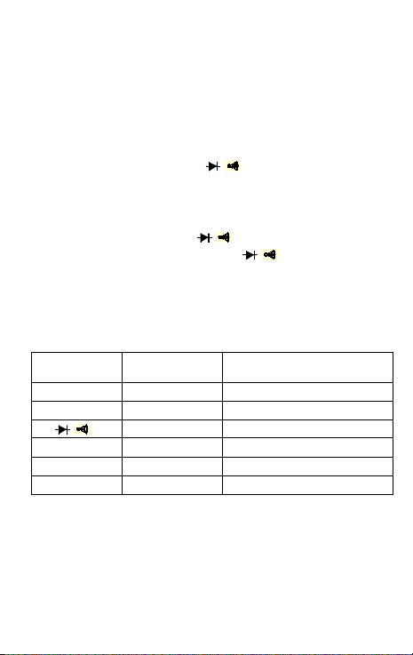
3.6 TESTING DIODE & CONTINUITY
1. Connect the black test lead to the COM jack and the
red test lead to the V//F jack. ( NOTE: The polarity of
red lead connection is positive+.)
2. Set the rotary switch at /position and push the
/button to select continuity or diode test mode.
3. In continuity testing, if continuity exists (i.e.,
resistance less than about 50), built-in buzzer will
sound.
4. If diode test mode is selected, connect the red and
black leads to the anode and cathode of the diode
under test. The forward voltage drop of this diode in V