Page 2
The information contained in this manual was accurate
at the time of release. Specifications are subject to
change without notice.
Warranty - All King Engineering products are
guaranteed to be free from defects in material and
workmanship for one year from the date of purchase.
Any product or part found to be defective under normal
use within one year of purchase will be repaired or
replaced at no charge if returned to the company at
Ann Arbor, Michigan within ten days of discovery of
the defect. No other warranties, whether expressed,
implied or statutory, including the warranties of fitness
for a particular purpose or merchantability, are given by
this agreement. The exclusive remedy for nonconformity
of these goods shall be repair and/or replacement of
the nonconforming goods or parts.
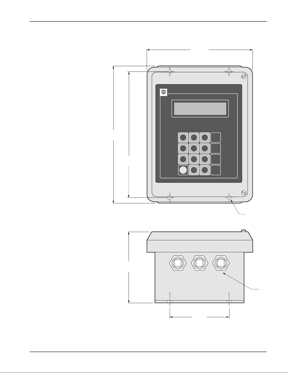
LevelPRO - Multiple Tank Level Processor EX-1803
Seller will not be liable for consequential damages
resulting from breach of this agreement. The term
“consequential damages” shall include but shall not
be limited to damage to all machines, equipment and
goods other than the goods sold hereby, interruption
of production, loss of profits, delays of any kind,
administrative expense and overhead.
©1997 King Engineering Corporation. All rights reserved.
®KING-GAGE and the KE emblem are registered trademarks and
LevelPRO is a trademark of King Engineering Corporation,
Ann Arbor, Michigan, U.S.A.
Specifications subject to change without notice.
Revisions:
(A) January, 1997 – Original Release
(B) July, 1997 – Revised with LED status and
communications sample response
(C) January, 1998 - 734 Area Code update
(D) March, 1998 - LevelPRO response (pg 12)