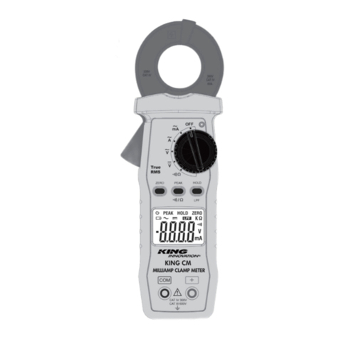
King Innovation KING 95 User manual

KING 95
CLAMP METER
INSTRUCTION MANUAL
True RMS
Milliamp Clamp Meter
#42095
31318 84

2
I
KING INNOVATION KING INNOVATION
I
3
MILLIAMP CLAMP METER
1. SAFETY INFORMATION
• Do not operate the tester if there is any sign of damage
to the tester or the test leads.
• Check the main function dial and make sure it is in the
correct position before each measurement.
• Do not perform resistance and continuity test on a live
power system.
• Do not apply voltage between the test terminals and test
terminal to ground that exceed the maximum limits stated
in this manual.
• Keep your fingers behind the protection ring on the test
probes when using the test leads.
• Change the battery when the symbol appears to
avoid incorrect data.
Environmental Conditions
Operation Temperature: 0°C to 40°C (32°F to 104°F);
<80 % RH
Storage Temperature: -10°C to 60°C (14°F to 140°F);
<80 % RH
Altitude: Up to 2000 meters
Pollution Degree: 2
Explanation of Symbols
Attention refer to operation instructions.
Approvals
TABLE OF CONTENTS
1. SAFETY INFORMATION........................................ 3
2. GENERAL SPECIFICATION................................... 4
3. ELECTRICAL SPECIFICATION............................... 5
3-1 ACmA Measurement............................................. 5
3-2 ACA Measurement................................................ 5
3-3 ACV Measurement ................................................ 6
3-4 DCV Measurement................................................ 6
3-5 Continuity ( )..................................................... 6
3-6 Resistance (Ω)........................................................ 6
4. DESCRIPTION.............................................................. 7
4-1 Description of the display ..................................... 7
4-2 Description of front and rear ................................ 8
5. BUTTON INSTRUCTION ........................................ 9
5-1 HOLD & LPF Function............................................ 9
5-2 PEAK HOLD Function............................................ 9
5-3 ZERO Function....................................................... 9
5-4 BACKLIGHT Function............................................ 10
6. MEASURING INSTRUCTION.............................. 10
6-1 ACA & ACmA Measurement................................ 10
6-2 ACV Measurement ................................................ 12
6-3 DCV Measurement................................................ 13
6-4 Continuity Measurement....................................... 13
6-5 Resistance Measurement ...................................... 14
7. CHANGING THE BATTERY................................... 14,15
8. MAINTENANCE.......................................................... 15
8-1 Cleaning................................................................. 15
CONFORMS TO UL STD. 61010-1,
61010-2-032, 61010-2-033
CERTIFIED TO CSA STD. C22.2 #61010-1-12,
61010-2-032, 61010-2-033
3131884

4
I
KING INNOVATION KING INNOVATION
I
5
MILLIAMP CLAMP METERINSTRUCTION MANUAL
2. GENERAL SPECIFICATION
The King Innovation KING 95 Digital Milliamp Clamp Meter is
ideal for use in troubleshooting two-wire irrigation, landscape
lighting and electrical systems. The KING 95 is for use in
indoor and outdoor dry locations.
Digital Display:
4 digit liquid crystal (LCD) maximum reading 6000
Polarity:
When a negative signal is applied, the ““signal appears.
Low Battery Indication:
When the battery voltage is below that required for proper
operation when the symbol will appear on the LCD
display.
Sample Rate:
2 times/sec for digital data.
Power Source:
1.5 size AAA battery X 2
Typical battery life: (without buzzer, backlight)
40 hours at ACmA and ACA function;
60 hours at DCV and Ohm function. (alkaline battery)
Auto Power Off:
If a key is not pressed or dial operated for 30 minutes, the
meter will power itself off to save battery life. This function can
be disabled by pressing and holding the “HOLD” button and
powering on the unit.
Over Load:
When the applied signal is larger than the maximum for the
range in use the display will show OL.
Maximum Jaw Opening:
.79” (20mm)
Dimensions:
8.27” x 2.87” x 1.50” (210 x 73 x 38mm)
Accessories:
Carrying case, batteries, test leads and instruction manual.
3. ELECTRICAL SPECIFICATION
The accuracy specification is defined as ± (percent of reading
+ digit) at 23±5°C, ≤80 %RH.
Safety Class - CAT III 600V
3-1 ACmA (True RMS)
Zero correction: Fractions smaller than approximately 0.006
mA are calibrated to zero.
Low Pass Filter
3-2 ACA (True RMS)
Low Pass Filter
Range Resolution Accuracy
50~60Hz 60~500Hz
6.000mA 0.001mA (1μA) 1.0% + 8dgts 2.0% + 8dgts
60.00mA 0.01mA (10μA) 1.0% + 5dgts 2.0% + 5dgts
600.0mA 0.1mA (100μA)
Range Resolution Accuracy
6.000mA 0.001mA 2.0% + 8dgts
60.00mA 0.01mA 2.0% + 5dgts
600.0mA 0.1mA
Range Resolution Accuracy
6.000A 0.001A 2.0% + 5dgts
60.00A 0.01A
Range Resolution Accuracy
50~60Hz 60~500Hz
6.000A 0.001A 1.0% + 5dgts 2.0% + 5dgts
60.00A 0.01A

6
I
KING INNOVATION KING INNOVATION
I
7
MILLIAMP CLAMP METERINSTRUCTION MANUAL
3-3 ACV (True RMS)
Input impedance: 2MΩ
3-4 DCV
Input impedance: 2MΩ
3-5 Continuity
3-6 Resistance (Ω)
Range Resolution Accuracy
50~500Hz
60.00V 0.01V 1.0% + 3dgts
600.0V 0.1V
Range Resolution Accuracy
60.00V 0.01V 1.0% + 2dgts
600.0V 0.1V
Range Resolution Accuracy
600.0Ω0.1Ω
1.0% + 2dgts
6.000KΩ0.001KΩ
60.00KΩ0.01KΩ
600.0KΩ0.1KΩ
Range Buzzer Function
Ohm < 45Ω
4. DESCRIPTION
4-1 Description of the display
Auto power off indication
Polarity indication
Low battery indication
~
AC measurement indication
DC measurement indication
ACurrent measurement indication
VVoltage measurement indication
ZERO ZERO indication
HOLD Data HOLD indication
PEAK PEAK hold indication
Low pass filter indication
Continuity test indication
K
Measurement unit
Ω Resistance measurement indication
mMeasurement unit

8
I
KING INNOVATION KING INNOVATION
I
9
MILLIAMP CLAMP METERINSTRUCTION MANUAL
4-2 Description of front and rear
1 Current Sensing Clamp
2 Safety Protection Ring
3 Backlight Button
4 Clamp Opening Handle
5 Function Select Dial
6 ZERO Button
7 PEAK and /ΩButtons
8 Data HOLD & LPF Button
9 LCD Display
10 COM Input Terminal
11 Positive Input Terminal
12 Battery Cabinet
12
5. BUTTON INSTRUCTION
5-1 HOLD & LPF Function
It’s possible to hold the displayed value by pressing on the
“HOLD” button. Press the “HOLD” button again to exit
the “HOLD” mode.
To activate the Low Pass Filter (LPF) feature, press and hold
the “LPF” button until the symbol displays. To deactivate
the “LPF” feature, press and hold the “LPF” button for 2
seconds. The meter will return to normal mode of operation.
The Cut-Off frequency of the low pass filter is about 160Hz
with attenuation characteristic of approx. -24dB/octave.
Note: the LPF function operates on the AC A and AC mA
ranges.
5-2 PEAK Hold and /ΩFunction Selection
Press “PEAK” button to enter the “PEAK” mode, the meter
records the peak maximum value. Press the “PEAK” button
again, to exit the peak mode.
When you turn the rotary switch to the Ohms/Continuity
Test position, press the “PEAK” button to select continuity
test with buzzer.
5-3 ZERO Function
Press “ZERO” button to enter the “ZERO” mode, ZERO
Indicator will appear and the display will ZERO. The
reading is stored as reference value for the subsequent
measurement.
Press the “ZERO” button again, to exit the ZERO mode.

10
I
KING INNOVATION KING INNOVATION
I
11
MILLIAMP CLAMP METERINSTRUCTION MANUAL
5-4 BACKLIGHT Function
When the “☼“ button is pressed, the backlight will be
turned on. Press the button again to turn the backlight off.
If the button is not pressed again then the backlight will
be automatically turned off in about 30 seconds after it’s
turned on.
6. MEASURING INSTRUCTION
6-1 ACA, ACmA Measurement:
(1) Set the range selector switch to the desired position.
The current to be measured should be within the measuring
range.
(2) Normal measurement (see Fig. 1):
Press the clamp opening handle to open the clamp
meter jaws and close them over one conductor only. The
measured current value is shown on the display. Earth
leakage current or any small AC current that flows through
a ground wire can also be measured by this method.
NOTE: Keeping the cable in the center of the clamp will
return more accurate test results when making current
measurements. Zero meter to accurately measure low
milliamp circuits.
(3) Measuring out of balance leakage current (see Fig. 2):
Clamp onto all conductors except the ground wire. The
measured imbalance current value is shown on the display.
Before this measurement, disconnect any test leads from the
meter for safety.
In some cases wherein reading the display is difficult, press
the HOLD button and read the result after the clamp is
removed from the conductors.
Fig. 1 Normal Measurement:
INCORRECT CORRECT
Fig. 2 Measuring out of balance leakage current:
LOAD
3-Phase 3-Wire System Single-Phase 2-Wire System
LOAD

12
I
KING INNOVATION KING INNOVATION
I
13
MILLIAMP CLAMP METERINSTRUCTION MANUAL
6-2 ACV Measurement:
WARNING!
Maximum Input Voltage is 600V AC/DC. Do not attempt
to take any voltage measurement that may exceed this
maximum to avoid Electrical Shock hazard and/or
damage to this instrument.
Switch the main function selector to ṽrange. Connect the
red test lead to the “+” terminal and the black lead to the
“COM” terminal. Measure the voltage by touching the test
lead tips to the test circuit where the voltage measurement
is required. Read the result from the LCD display.
6-3 DCV Measurement:
Switch the main function selector to V range. Connect the
red test lead to the “+” terminal and the black lead to the
“COM” terminal. Measure the voltage by touching the
test lead tips to the test circuit where the value of voltage is
needed. Read the result from the LCD display.
6-4 Continuity Test with Buzzer:
Switch the main function to Ωrange. Connect the red test
lead to the “+” terminal and the black lead to the “COM”
terminal. Connect tip of the test leads to the points between
which continuity is to be measured. If the resistance is under
45 Ω, the beeper will sound continuously.
NOTE:
When measuring resistance in a circuit, make sure any power
on the circuit is turned off and any capacitors are discharged.
Short Circuit Open Circuit

14
I
KING INNOVATION KING INNOVATION
I
15
MILLIAMP CLAMP METERINSTRUCTION MANUAL
6-5 Resistance Measurement:
Switch the main function selector to Ωrange. Connect the
red test lead to the “+” terminal and the black lead to the
“COM” terminal. Connect tip of the test leads to the points
where the value of the resistance is to be measured. Read
the result from the LCD.
NOTE:
When measuring resistance in a circuit, make sure any
power on the circuit is turned off and any capacitors are
discharged.
7. CHANGING THE BATTERY
When the battery voltage drops below that required for
proper operation of the instrument, the battery symbol will
appear on the LCD display and the batteries should be
changed. Before changing the batteries, switch the main dial
to “OFF” and disconnect test leads. Open the back cover
using a screwdriver. Replace the old batteries with two new
1.5V (AAA Size) batteries. Close the back cover and tighten
the screw before using the meter.
NOTE: If the meter is not going to be used for a long time
then remove the batteries and store meter in a cool, dry
location. Do not store meter in a high temperature or high
humidity environment.
8. MAINTENANCE
WARNING!
Before opening the meter, disconnect both test leads.
Never use the meter unless the battery cover is in place
and the screw is tightened.
8-1 Cleaning:
Periodically wipe the case with a dry cloth. Do not use
abrasives or solvents.

©2020 King Innovation
42 N. Central Drive
O'Fallon, MO 63366
www.kinginnovation.com
800.624.4320
MADE IN CHINA
REV E 11/20
©2020 King Innovation
O'Fallon, MO 63366
42 N. Central Drive
www.kinginnovation.com
800.624.4320
HECHO EN CHINA
REV E 11/20

14
I
KING INNOVATION KING INNOVATION
I
15
AMPERÍMETRO DE PINZA EN MILIAMPERIOSMANUAL DE INSTRUCCIONES
6-5 Medición de resistencia:
Cambie el selector de función principal al rango Ω.
Conecte el conductor de prueba rojo al terminal “+” y el
conductor de prueba negra al terminal “COM”. Conecte las
puntas de los conductores de prueba a los puntos donde se
va a medir la resistencia. Lea el resultado en la LCD.
NOTA:
Cuando mida resistencia en un circuito, cerciórese de que
el circuito no tenga electricidad y los condensadores estén
descargados.
7. CAMBIO DE BATERÍA
Cuando el voltaje de la batería está por debajo de lo
requerido para el funcionamiento adecuado aparece el
símbolo de batería en la LCD. Antes de reemplazar las
baterías, coloque el dial principal en “OFF” (apagado) y
desconecte los conductores de prueba. Abra la cubierta
posterior con un destornillador. Reemplace las baterías
viejas con dos nuevas AAA de 1.5VDC. Cierre la cubierta
posterior y apriete el tornillo antes de usar el amperímetro.
NOTA: Si el amperímetro no se va a usar por largo tiempo
retire las baterías y guarde el amperímetro en un lugar seco
y fresco. No guarde el amperímetro en un ambiente de alta
temperatura o alta humedad.
8. MANTENIMIENTO
¡ADVERTENCIA!
Antes de abrir el amperímetro, desconecte ambos
conductores de prueba. Nunca use el amperímetro sin la
cubierta de la batería en su lugar y el tornillo apretado.
8-1 Limpieza:
Limpie periódicamente el estuche con un paño seco. No use
abrasivos ni disolventes.

12
I
KING INNOVATION KING INNOVATION
I
13
AMPERÍMETRO DE PINZA EN MILIAMPERIOSMANUAL DE INSTRUCCIONES
6-2 Medición de voltaje de corriente alterna (VCA):
¡ADVERTENCIA!
El voltaje de entrada máximo es de 600V CA/CD. No
intente hacer mediciones de cualquier voltaje que exceda
este máximo para evitar el riesgo de descarga eléctrica
y/o daños a este instrumento.
Cambie el selector de función principal al rango ṽ. Conecte
el conductor de prueba rojo al terminal “+” y el conductor de
prueba negro al terminal “COM”. Mida el voltaje tocando
las puntas de los conductores de prueba al circuito de prueba
donde necesite medir el voltaje. Lea el resultado en la LCD.
6-3 Medición de voltaje de corriente directa (VCD):
Cambie el selector de función principal al rango V. Conecte
el conductor de prueba rojo al terminal “+” y el conductor
de prueba negro al terminal “COM”. Mida el voltaje
tocando las puntas de los conductores de prueba al circuito
de prueba donde necesite medir el voltaje. Lea el resultado
en la LCD.
6-4 Pruebe la continuidad con el indicador acústico
(Buzzer):
Cambie el selector de función principal al rango Ω.
Conecte la punta de prueba roja al terminal “+” y la punta
de prueba negra al terminal “COM”. Conecte las puntas de
los conductores de prueba a los puntos entre los cuales se va
a medir la continuidad. Si la resistencia es menor de 45Ω, el
indicador acústico sonará continuamente.
NOTA:
Cuando mida resistencia en un circuito, cerciórese de que
el circuito no tenga electricidad y los condensadores estén
descargados.
Corto circuito Circuito abierto

10
I
KING INNOVATION KING INNOVATION
I
11
AMPERÍMETRO DE PINZA EN MILIAMPERIOSMANUAL DE INSTRUCCIONES
5-4 Función luz de fondo
Cuando se presiona el botón con el símbolo de luz “☼”, la
luz de fondo se encenderá. Presione el botón nuevamente
para apagar la luz posterior. Si no se presiona nuevamente
el botón, la luz posterior se apagará automáticamente en
unos 30 segundos después de haberla encendido.
6. INSTRUCCIONES DE MEDICIÓN
6-1 Medición de ACA y mACA
(1) Coloque el selector en el rango deseado. La corriente a
medir debe estar dentro del rango de medición.
(2) Medición normal (ver Fig. 1):
Presione la manija de abertura de la pinza para abrir las
mordazas de pinza del amperímetro y luego ciérrelas sobre
un solo conductor. El valor de la corriente medida se muestra
en la pantalla. La corriente de fuga a tierra o cualesquier
pequeña corriente alterna (CA) que circule a través del cable
a tierra se pueden medir mediante este método.
NOTA: Mantener el cable en el centro de la pinza
proporcionará resultados de prueba más precisos cuando
haga mediciones de corriente. Cero medidor para medir
con precisión circuitos de miliamperios bajos.
(3) Medición de corriente de fuga desbalanceada
(ver Fig. 2):
Abrace con la pinza todos los conductores excepto el
cable a tierra. El valor de la corriente desbalanceada
medida aparecerá en la pantalla. Antes de esta medición
desconecte del amperímetro cualquier conductor de
prueba, por seguridad.
En algunos casos donde sea difícil leer la pantalla, presione
el botón “HOLD” (retención) y lea el resultado después de
quitar la pinza de los conductores.
Fig. 1 Medición normal:
INCORRECTA CORRECTA
Fig. 2 Medición de corriente de fuga desbalanceada:
LOAD
(carga) LOAD
(carga)
Sistema trifásico -3 cables Sistema monofásico - 2 cables

8
I
KING INNOVATION KING INNOVATION
I
9
AMPERÍMETRO DE PINZA EN MILIAMPERIOSMANUAL DE INSTRUCCIONES
4-2 Descripción del frente y la parte posterior
1 Pinza de sensor de corriente
2 Aro de protección de seguridad
3 Botón de luz de fondo
4 Manija de abertura de la pinza:
5 Dial de selección de función
6 Botón “ZERO” (cero)
7 Botones de “PEAK” (pico) y / Ω(resistencia)
8 Botón de “HOLD” (retención) de datos y “LPF”
filtro de paso bajo)
9 Pantalla de cristal líquido (LCD) de 9 dígitos
10 Terminal de entrada “COM”
11 Terminal de entrada del positivo
12 Compartimento de batería
12
5. BOTÓN DE INSTRUCCIÓN
5-1 Función de retención y ltro de paso bajo
Es posible retener el valor mostrado presionando el
botón “HOLD” (retención). Presione el botón “HOLD”
(retención) nuevamente para salir del modo “HOLD”
(retención).
Para activar la función filtro de paso bajo, mantenga
presionado el botón “LPF” (filtro de paso bajo) hasta que
aparezca el símbolo. Para desactivar la función filtro de
paso bajo mantenga presionado el botón “LPF” (filtro de
paso bajo) por 2 segundos. El amperímetro regresará al
modo de funcionamiento normal.
La frecuencia de corte del filtro de paso bajo e alrededor
de 160Hz con característica de atenuación de aprox.
-24dB por octavo.
Nota: La función de filtro de paso bajo funciona en los
rangos ACA y mACA.
5-2 Selección de la función retención pico /Ω
Presione el botón “PEAK” (pico) para ingresar en el
modo pico, el amperímetro registra el valor pico máximo.
Presione el botón “PEAK” (pico) nuevamente para salir
del modo pico.
Cuando gire el interruptor giratorio a la posición de
prueba de Ohms/Continuidad, presione el botón “PEAK”
(pico) para seleccionar la prueba de continuidad con el
indicador acústico (Buzzer).
5-3 Función ZERO
Presione el botón “ZERO” (cero) para ingresar al modo
“ZERO” (cero), aparecerá en pantalla el indicador
“ZERO” (cero). La lectura se almacena como valor de
referencia para la medición subsiguiente.
Presione el botón “ZERO” (cero) nuevamente para salir
del modo “ZERO” (cero).

6
I
KING INNOVATION KING INNOVATION
I
7
AMPERÍMETRO DE PINZA EN MILIAMPERIOSMANUAL DE INSTRUCCIONES
3-3 Voltaje de corriente alterna (VCA) [(Valor
Real - Raíz Media Cuadrática (True RMS)]
Impedancia de entrada : 2MΩ
3-4 Voltaje de corriente directa (VCD)
Impedancia de entrada: 2MΩ
3-5 Continuidad
3-6 Resistencia (Ω)
Rango Resolución Precisión
50~500Hz
60.00V 0.01V 1.0% + 3 dígitos
600.0V 0.1V
Rango Resolución Precisión
60.00V 0.01V 1.0% + 2 dígitos
600.0V 0.1V
Rango Resolución Precisión
600.0Ω0.1Ω
1.0% + 2 dígitos
6.000KΩ0.001KΩ
60.00KΩ0.01KΩ
600.0KΩ0.1KΩ
Rango Función de indicador acústico
(Buzzer)
Ohm < 45Ω
4. DESCRIPCIÓN
4-1 Descripción de la pantalla
Indicación de apagado automático
Indicación de polaridad
Indicación de batería baja
~
Indicación de medición de corriente alterna (CA)
Indicación de medición de corriente directa (CD)
AIndicación de medición de corriente
VIndicación de medición de voltaje
“ZERO”
(cero) Indicación de “ZERO” (cero)
“HOLD”
(retención) Indicación de “HOLD” (retención) datos
“PEAK”
(pico) Indicación de retención “PEAK” (pico)
Indicación de filtro de paso bajo
Indicación de prueba de continuidad
K
Unidad de medición
Ω Indicación de medición de resistencia
mUnidad de medición

4
I
KING INNOVATION KING INNOVATION
I
5
AMPERÍMETRO DE PINZA EN MILIAMPERIOSMANUAL DE INSTRUCCIONES
2. ESPECIFICACIONES GENERALES
El medidor digital tipo pinza en miliamperios KING 95 de King
Innovation es ideal para usar en procedimientos para la solución de
problemas en sistemas de irrigación de dos conductores, sistemas de
iluminación paisajística y sistemas eléctricos. El KING 95 es para uso
en lugares secos interiores y exteriores.
Pantalla digital:
Pantalla de cristal líquido (LCD) de 4 dígitos, lectura máxima 6000
Polaridad:
Cuando se aplica una señal negativa, aparece la señal “ “.
Indicación de batería baja:
Cuando el voltaje de la batería está por debajo de lo requerido
para el funcionamiento adecuado aparece el símbolo “ “ en la
pantalla LCD.
Índice de muestreo:
2 veces /secuencia para datos digitales.
Fuente de alimentación:
2 baterías AAA 1.5V
Vida típica de la batería: (Sin indicador acústico, ni luz de fondo)
40 horas en función mACA y ACA;
60 horas en función VCD y Ohm. (batería alcalina)
Apagado automático:
Si no se presiona una tecla o se mueve el dial en 30 minutos, el
amperímetro se apagará para ahorrar la batería. Esta función se
puede deshabilitar manteniendo presionando el botón “HOLD” y
encendiendo la unidad.
Sobrecarga:
Cuando la señal aplicada es mayor que el máximo para el rango en
uso, la pantalla mostrará “OL” (sobrecarga).
Máxima abertura de la pinza:
.79” (20mm)
Dimensiones:
8.27” x 2.87” x 1.50” (210 x 73 x 38mm)
Accesorios:
Estuche transportador, baterías, conductores de prueba y manual de
instrucciones.
3. ESPECIFICACIONES ELÉCTRICAS
La especificación de precisión se define como ± (porcentaje
de lectura + dígito) a 23±5°C, Humedad relativa (RH.) ≤80 %
Clasicación de seguridad – Clasicación III 600V
3-1 Miliamperios de corriente alterna (mACA) [Valor
Real de la Raíz Media Cuadrática (True RMS)]
Corrección a cero: Las fracciones inferiores a 0.006 mA se
calibran a cero.
Filtro de paso bajo
3-2 Miliamperios de corriente alterna (mACA) [Valor
Real - Raíz Media Cuadrática (True RMS)]
Filtro de paso bajo
Rango Resolución Precisión
50~60Hz 60~500Hz
6.000mA 0.001mA (1μA) 1.0% + 8dgts 2.0% + 8
dígitos
60.00mA 0.01mA (10μA) 1.0% + 5dgts 2.0% + 5
dígitos
600.0mA 0.1mA (100μA)
Rango Resolución Precisión
6.000mA 0.001mA 2.0% + 8 dígitos
60.00mA 0.01mA 2.0% + 5 dígitos
600.0mA 0.1mA
Rango Resolución Precisión
6.000A 0.001A 2.0% + 5 dígitos
60.00A 0.01A
Rango Resolución Precisión
50~60Hz 60~500Hz
6.000A 0.001A 1.0% + 5
dígitos
2.0% + 5
dígitos
60.00A 0.01A

KING INNOVATION
I
3
AMPERÍMETRO DE PINZA EN MILIAMPERIOS
2
I
KING INNOVATION
1. INFORMACIÓN DE SEGURIDAD
• No use el instrumento de prueba si hay señales de daño en
el instrumento de prueba o en los conductores de prueba.
• Revise el dial de función principal y cerciórese de que esté
en la posición correcta antes de cada medición.
• No realice prueba de resistencia y continuidad en un
sistema de electricidad vivo.
• No aplique voltaje entre los terminales de prueba y
el terminal a tierra que exceda los límites máximos
establecidos en este manual.
• Mantenga sus dedos detrás del aro de protección en los
sondeos de prueba cuando use los conductore de prueba.
• Cambie la batería cuando aparezca el símbolo para
evitar datos incorrectos.
Condiciones ambientales
Temperatura de funcionamiento.: 0°C a 40°C (32°F a
104°F); Humedad relativa (RH) <80%
Temperatura de almacenaje: -10°C a 60°C (14°F a 140°F);
Humedad relativa (RH) <80%
Altitud: Hasta 2.000 metros
Grado de contaminación: 2
Explicación de símbolos
Atención: Refiérase a las instrucciones de funcionamiento:
Aprobaciones
ÍNDICE
1. INFORMACIÓN DE SEGURIDAD ..................... 3
2. ESPECIFICACIONES GENERALES .................... 4
3. ESPECIFICACIONES ELÉCTRICAS .................... 5
3-1 Medición de miliamperios de corriente alterna . 5
3-2 Medición de Amperios de corriente alterna ..... 5
3-3 Medición de voltaje de corriente alterna ........... 6
3-4 Medición de voltaje de corriente directa............ 6
3-5 Continuidad ( ) ................................................. 6
3-6 Resistencia (Ω)....................................................... 6
4. DESCRIPCIÓN.............................................................. 7
4-1 Descripción de la pantalla ................................... 7
4-2 Descripción de la parte frontal y posterior......... 8
5. BOTÓN DE INSTRUCCIÓN.................................. 9
5-1 Función de retención y de filtro de paso bajo.... 9
5-2 Función de retención de pico............................... 9
5-3 Función cero........................................................... 9
5-4 Función de luz de fondo....................................... 10
6. INSTRUCCIONES PARA LAS MEDICIONES10
6-1 Medición de Amperios de corriente alterna y
miliamperios de corriente alterna............................... 10
6-2 Medición de voltaje de corriente alterna ........... 12
6-3 Medición de voltaje de corriente directa ........... 13
6-4 Medición de continuidad ..................................... 13
6-5 Medición de Resistencia ...................................... 14
7. CAMBIO DE BATERÍA.............................................. 14,15
8. MANTENIMIENTO.................................................... 15
8-1 Limpieza ................................................................. 15
CONFORMS TO UL STD. 61010-1,
61010-2-032, 61010-2-033
CERTIFIED TO CSA STD. C22.2 #61010-1-12,
61010-2-032, 61010-2-033
3131884

AMPERÍMETRO
DE PINZA
KING 95
MANUAL DE INSTRUCCIONES
Valor Real- Raíz Media
Cuadrática (True RMS)
Amperímetro de pinza
en miliamperios
#42095
KING 95
CLAMP METER
31318 84
This manual suits for next models
1
Table of contents
Other King Innovation Measuring Instrument manuals