2
I
KING INNOVATION KING INNOVATION
I
3
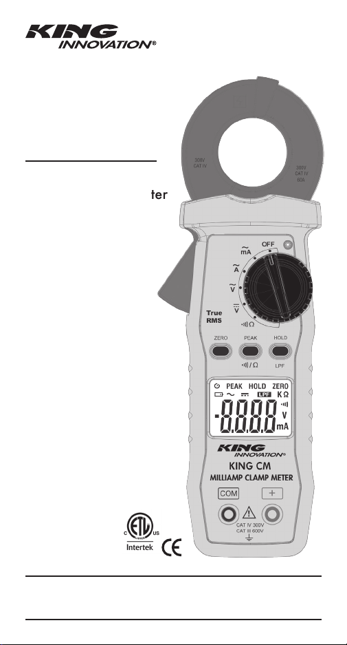
MILLIAMP CLAMP METER
1. SAFETY INFORMATION
• Never attempt to make any measurement if any
abnormal conditions are noted, such as broken case,
cracked test leads and exposed metal part.
• Set the Function Switch to an appropriate
position before starting measurement.
• Do not perform resistance and continuity test on a live
power system.
• Do not apply voltage between the test terminals and test
terminal to ground that exceed the maximum limits stated
in this manual.
• Keep your fingers behind the protection ring on the test
probes when using the test leads.
• Change the battery when the symbol appears to
avoid incorrect reading.
Environmental Conditions
Operation Temperature: 0°C to 40°C (32°F to 104°F);
<80 % RH
Storage Temperature: -10°C to 60°C (14°F to 140°F);
<80 % RH
Altitude: Up to 2000 meters
Pollution Degree: 2
Explanation of Symbols
Attention refer to operation instructions.
Approvals
1. SAFETY INFORMATION........................................3
2. GENERAL SPECIFICATION...................................4
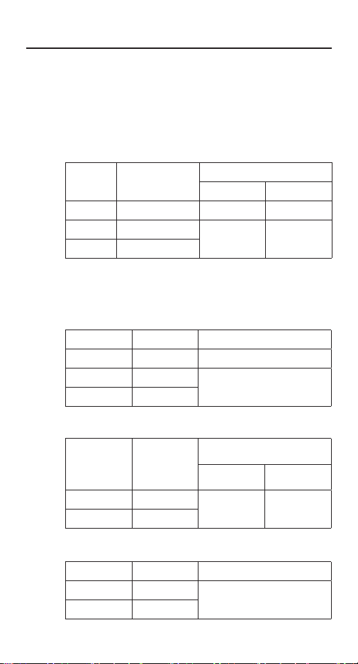
3. ELECTRICAL SPECIFICATION...............................5
3-1 ACmA Measurement.............................................5
3-2 ACA Measurement................................................5
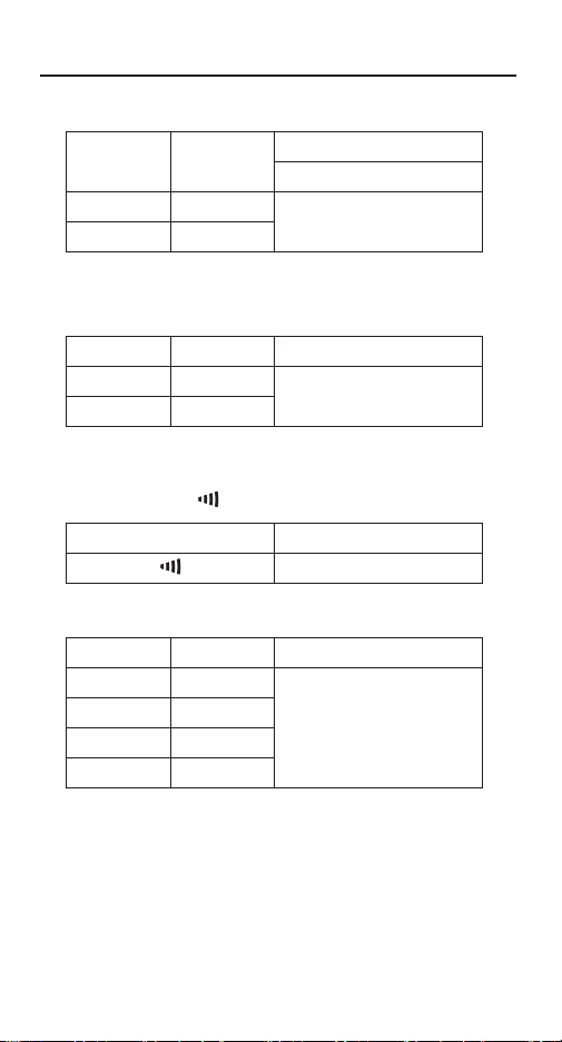
3-3 ACV Measurement ................................................6
3-4 DCV Measurement................................................6
3-5 Continuity ( ) ....................................................6
3-6 Resistance (Ω)........................................................6
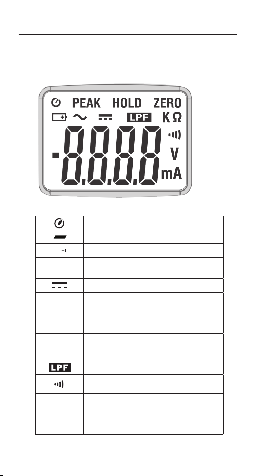
4. DESCRIPTION..............................................................7
4-1 Description of the display .....................................7
4-2 Description of front and rear ................................8
5. BUTTON INSTRUCTION ........................................9
5-1 HOLD & LPF Function............................................9
5-2 PEAK HOLD Function............................................9
5-3 ZERO Function.......................................................9
5-4 BACKLIGHT Function..........................................10
6. MEASURING INSTRUCTION............................10
6-1 ACA & ACmA Measurement..............................10
6-2 ACV Measurement ..............................................12
6-3 DCV Measurement..............................................13
6-4 Continuity Measurement.....................................13
6-5 Resistance Measurement ....................................14
7. CHANGING THE BATTERY........................... 14,15
8. MAINTENANCE........................................................15
8-1 Cleaning...............................................................15
CONFORMS TO UL STD. 61010-1,
61010-2-032, 61010-2-033
CERTIFIED TO CSA STD. C22.2 #61010-1-12,
61010-2-032, 61010-2-033
3131884