King Innovation 521 User manual

INSTRUCTION MANUAL
KING 521 #42521
CAUTION
Read and understand all of
the instructions and safety
information in this manual before
operating or servicing this tool.
WIRE AND VALVE LOCATING SYSTEM

2
I
KING INNOVATION KING INNOVATION
I
3
KING 521INSTRUCTION MANUAL
TABLE OF CONTENTS
DESCRIPTION ............................................................................... 2
SAFETY .......................................................................................... 2
PURPOSE OF THIS MANUAL........................................................ 2
IMPORTANT SAFETY INFORMATION .......................................... 3-4
IDENTIFICATION .......................................................................... 5
SETUP............................................................................................ 6
OPERATION .................................................................................. 7-10
SPECIFICATIONS........................................................................... 11
MAINTENANCE............................................................................. 11
BATTERY REPLACEMENT............................................................... 11
DESCRIPTION
King Innovation’s KING 521 Wire and Valve Locating System is a
universal troubleshooting and maintenance tool for locating the
wire path, depth, wire breaks, large nicks, and solenoid valves.
SAFETY
Safety is essential in the use and maintenance of King Innovation
tools and equipment. This instruction manual and any markings
on the tool provide information for avoiding hazards and unsafe
practices related to the use of this tool. Observe all of the safety
information provided.
PURPOSE OF THIS MANUAL
This instruction manual is intended to familiarize all personnel
with the safe operation and maintenance procedures for the King
Innovation KING 521 Wire and Valve Locating System. Keep this
manual available to all personnel.
KEEP THIS MANUAL
IMPORTANT SAFETY INFORMATION
DANGER
Immediate hazards which, if not avoided, WILL result in
severe injury or death.
WARNING
Hazards which, if not avoided, COULD result in
severe injury or death.
CAUTION
Hazards or unsafe practices which, if not avoided,
MAY result in injury or property damage.
WARNING
Read and understand this material before operating
or servicing this equipment.
Failure to understand how to safely operate this tool
could result in an accident causing serious injury or death.
DANGER is reserved for conditions and actions that are
likely to cause serious or fatal injury.
WARNING is reserved for conditions and actions that can
cause serious or fatal injury.
CAUTION is reserved for conditions and actions that can
cause injury or instrument damage.

4
I
KING INNOVATION KING INNOVATION
I
5
KING 521INSTRUCTION MANUAL
IMPORTANT SAFETY INFORMATION
WARNING
Electric Shock Hazard. Contact with live circuits could result
in severe injury or death.
WARNING
Electric shock hazard:
• Do not expose this unit to rain or moisture
• Use this unit for the manufacturer’s intended purpose only, as
described in this manual. Any other use can impair the protection
provided by the unit.
• Use test leads or accessories that are appropriate for the
application. Refer to the category and voltage rating of the
test lead or accessory.
• Inspect the test leads or accessory before use. They must be clean
and dry, and the insulation must be in good condition.
• Before removing the case or battery cover, remove the test leads
from the circuit and shut off the unit.
Failure to observe these warnings could result in
severe injury or death.
CAUTION
Electric Shock Hazard. Do not connect transmitter to any
active AC circuits.
Failure to observe this precaution may result in injury and
can damage the instrument.
CAUTION
Electric Shock Hazard. Do not attempt to repair this unit.
It contains no user-serviceable parts.
Failure to observe this precaution may result in injury
and can damage the instrument.
King 521 Wire and Valve Locating System Includes:
1. Headset
2. Ground Stake
3. Transmitter
4. Receiver
5. Carrying Case
6. Black Lead
7. Red Lead
8. Selector knob
9. On/Off Switch
10. Battery Cover
1 2 3 4 5
6 7 8 9 10

6
I
KING INNOVATION KING INNOVATION
I
7
KING 521INSTRUCTION MANUAL
OPERATION
Locating Wire Path
With the probe pointed toward the ground, walk completely around
the transmitter location. An absence of tone or null will be detected
directly over the path of the wire. Movement to either side will
cause the volume of tone signal intensity to increase. Follow the
null to determine the wire path. (Refer to Figure 2).
Finding Wire Breaks and Nicks
When attempting to find breaks and nicks, you should decrease
the sensitivity of the receiver when pointing it off to either side of
the null. You will be able to notice the charge in signal intensity
immediately. Do not allow the meter to peg or go above 10. This
will greatly help in the fault locating process.
NOTE: The wire must have a path to ground to be successfully
located. These paths exists in a great majority of all direct buried
wires due to insulation imperfections, nicks, and bad splices. If
not, create one by grounding the remote end.
SETUP
NOTE: The transmitter produces high voltage. Turn the transmitter
off before handling the output leads. Disconnect all wires when
fault locating. Turn the selector knob to the BATTERY TEST
position. The meter should read between 8 and 10.
IMPORTANT: To ensure that the transmitter is producing optimum
signal, connect the red and black leads together and turn the unit
on. Turn the selector knob to position #5. The meter needle should
rise to at least a 10 reading.
1. With the transmitter off, connect the red lead to the wire to be located
and the black lead to a good earth ground with the stake provided.
(Refer to Figure 1)
2. Turn the transmitter on and start rotating the selector knob clockwise.
Once you leave the BATTERY TEST position and go to #1, the meter
needle will fall off to near zero. As you increase the output, the needle
will rise slightly with each advancement. Stop when the meter reads
between 4 and 8. The transmitter is now set for maximum efficiency for
this job. If a reading of 4 is not obtainable, reposition the ground stake.
3. Plug the optional handset into the receiver if desired, turn the receiver on
and point the antenna or probe end at the transmitter. A pulsing tone
should be heard and an indication should register on the receiver meter.
NOTE: High pitched tones from the headset may occur if the headset
cord gets to close to the receiver antenna or the receiver battery is low.
CAUTION Electric shock hazard:
Do not connect transmitter to any active AC circuits.
Failure to observe precaution may result in injury
and can damage the instrument.
FIGURE 1: Transmitter Setup
FIGURE 2: Locating Wire Path

8
I
KING INNOVATION KING INNOVATION
I
9
KING 521INSTRUCTION MANUAL
• The end of a cut or broken wire can be located by following
the path until the null disappears and gives way to a hot spot.
Beyond the hot spot, no null can be detected. Back up until the
null is detected, and this will be the approximate end of the
broken wire. (Refer to Figure 3)
• Larger nicks in the wire can be located in the same way as
locating cut wires. Follow the null and strong signal along the
sides of the wire until the signal becomes very weak along the
sides of the null. This will occur within a relatively short distance.
The transmitted signal bleeds to ground at the nick and then
wants to return to the ground stake along the outside of the wire
itself. The majority of the signals will stop at the nick indicated by
the low receiver reading just beyond the nick. (Refer to Figure 4)
• To more accurately define the location of an open or larger nick
(ground fault), position the receiver tip on the ground near the
point where the last strong signal was detected along the side of
the path. The receiver tip should be pointing at the ground and
be approximately 6 inches to either side from the null. Because
you are so much closer to the path, the sensitivity knob must be
adjusted down until the meter reads just below 10.
While maintaining the 6-inch distance from the null, move the
receiver down the line, paying close attention to the meter reading.
Once you pass the open or nick, the meter will fall off rapidly.
Determining Depth of Wire
To determine the depth of the wire, first mark the ground directly
over the path. Turn the receiver sideways to the path, and tip it 45
degrees. Move the receiver away from the path, maintaining the
45 degree tip until a null is detected. Mark this spot. The depth is
the distance between the two marks. (Refer to Figure 5)
Two-Step Solenoid Valve Locating Process
Solenoid valves can be located provided all the wires leading to
them are intact and the solenoid itself is still good.
Step 1
1. Set-up transmitter as in “Set-up Section”. The null will be present
until you pass over a solenoid valve, and then the signal will
become extremely strong. Mark this spot. Check around the
hot spot for a null leaving the area. If the null continues, follow
it and mark any additional hot spots. (Refer to Figure 6) If only
one hot spot or valve is located, it will be the valve in question.
FIGURE 3: Locating End
of Broken Wire
FIGURE 4:
Locating Wire Nick
FIGURE 5:
Determining Depth

10
I
KING INNOVATION KING INNOVATION
I
11
KING 521INSTRUCTION MANUAL
Specifications
Transmitter Frequency: 1748 Hz
Transmitter Power: 750 Vpp, 285 Vrms
Case Dimensions: 33.5in (851mm) x 8.25in (210mm)
x 3.75in (95mm)
Battery: Eight (8) D-cells and one 9V
Battery Life:
Receiver/Transmitter: 50 hours nominal
MAINTENANCE
BATTERY REPLACEMENT
Transmitter
1. Turn the unit off.
2. Remove the battery cover.
3. Install/replace the eight (8) D-cell batteries. (Observe polarity)
4. Replace the battery cover.
Receiver
1. Remove screw on each side of receiver.
2. Install /replace 9V battery. (Observe polarity)
3. Replace cover and screws.
Cleaning
Periodically wipe with a damp cloth and mild detergent;
do not use abrasives or solvents.
WARRANTY
King Innovation®products are guaranteed against faulty materials
or workmanship for a period of one year from date of purchase.
Contact factory for full warranty information.
For technical support, service inquiries or warranty requests,
call (877) 771-8885.
WARNING
Electric shock hazard:
Before removing the case or battery cover, remove the
test leads from the circuit and shut off the unit.
Failure to observe this warning could result in severe
injury or death.
Step 2
2. If more than one hot spot is found, mark them and return to the
transmitter and turn it off. Lift the black lead from the ground
stake and connect it to the common wire. Turn the transmitter
on, set the selector knob to the highest reading, and return to
the first hot spot with the receiver. Touch the tip of the receiver
antenna to the ground in the center of the first hot spot and
set the sensitivity knob to read near mid-scale. Now go to the
second spot and without touching the sensitivity knob, check the
strength of the signal at each hot spot and determine which, out
of all of them, is the strongest signal. This is the value for the
station wire you are connected to.
FIGURE 6: Determining Depth
Locating Broken Wire End

MADE IN CHINA
REV A 11/20
©2020 King Innovation
O'Fallon, MO 63366
www.kinginnovation.com
800.624.4320

FABRICADO EN CHINA
REV A 11/20
©2020 King Innovation
O'Fallon, MO 63366
www.kinginnovation.com
800.624.4320
ADVERTENCIA: Cáncer y Daños
Reproductivos – www.P65Warnings.ca.gov

10
I
KING INNOVATION KING INNOVATION
I
11
KING 521MANUAL DE INSTRUCCIONES
Especificaciones
Frecuencia del transmisor 1748 Hz
Potencia del transmisor: 750 Vpp, 285 Vrms
Dimensiones del estuche: 33,5 pulgadas (851 mm) x 8,25
pulgadas (210 mm) x 3,75 pulgadas (95 mm)
Batería: Ocho (8) baterías de tipo "D" y una de 9 V
Duración de las pilas:
Receptor/Transmisor: 50 horas nominales
MANTENIMIENTO
CAMBIO DE LAS BATERÍAS
Transmisor
1. Apague la unidad.
2. Saque la tapa de las baterías.
3. Coloque/reemplace las ocho (8) baterías de tipo D. (Respete la
polaridad)
4. Reemplace la tapa de las baterías.
Receptor
1. Extraiga el tornillo a cada lado del receptor.
2. Coloque/reemplace la batería de 9 V. (Respete la polaridad)
3. Vuelva a colocar la tapa y los tornillos.
Limpieza
Limpie periódicamente con un paño húmedo y detergente suave;
no use sustancias abrasivas ni disolventes.
GARANTÍA
Los productos King Innovation®están garantizados contra defectos
en los materiales o la mano de obra durante un período de un
año a partir de la fecha de la compra. Comuníquese con la fábrica
para obtener la información completa sobre la garantía.
Para soporte técnico, consultas de servicio o solicitudes de
garantía, llame (877) 771-8885.
ADVERTENCIA
Peligro de descargas eléctricas:
Antes de abrir la tapa de la caja o de las baterías, extraiga
los conductores de prueba del circuito y apague la unidad.
Si no se respeta esta advertencia, se podrían ocasionar
lesiones graves o la muerte.
Paso 2
2. Si se localiza más de un punto caliente, márquelos y regrese
al transmisor y apáguelo. Levante el conductor de color negro
de la punta de tierra y conéctelo al cable común. Encienda el
transmisor, ponga la perilla selectora en la lectura más alta
y regrese al primer punto caliente con el receptor. Conecte
la punta de la antena del receptor a la tierra en el centro del
primer punto caliente y ajuste la perilla de sensibilidad para que
lea cerca de la escala media. Ahora pase al segundo punto y
sin tocar la perilla de sensibilidad, verifique la potencia de la
señal en cada punto caliente y determine cuál de todos ellos
constituye la señal más potente. Este es el valor para el cable de
estación al que está conectado.
FIGURA 6: Determinación de
la profundidad al localizar el
extremo de un cable roto

8
I
KING INNOVATION KING INNOVATION
I
9
KING 521MANUAL DE INSTRUCCIONES
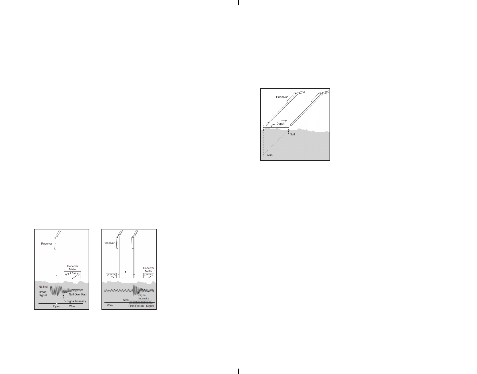
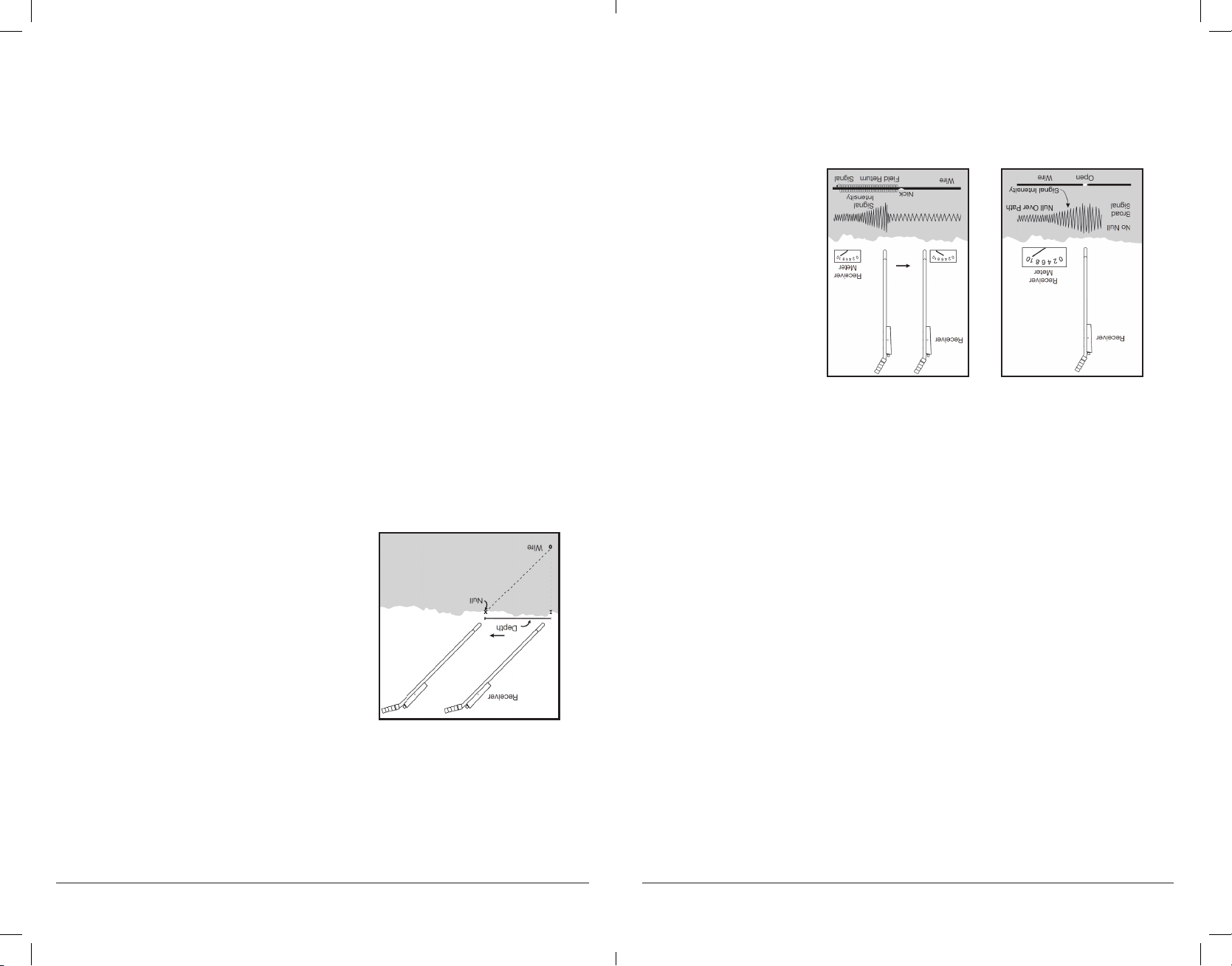
• El extremo de un cable cortado o roto se puede localizar siguiendo la
ruta hasta que desaparezca la respuesta nula y dé lugar a un punto
caliente. Más allá del punto caliente, no se puede detectar ninguna
respuesta nula. Retroceda hasta que se detecte la respuesta nula y este
será el extremo aproximado del cable roto. (Consulte la Figura 3)
• Se pueden localizar melladuras más grandes en el cable de la misma
manera que se localizan los cables cortados. Siga la señal nula y
potente a lo largo de los costados del cable hasta que la señal se
vuelva muy débil a lo largo de la respuesta nula. Esto ocurrirá dentro
de una distancia relativamente breve. La señal transmitida se purga a
tierra en la melladura y luego querrá regresar a la punta de tierra a lo
largo del exterior del cable mismo. La mayor parte de las señales se
detendrán en la melladura indicada por la lectura baja del receptor
apenas más allá de la melladura. (Consulte la Figura 4)
• Para definir con mayor precisión la ubicación de una melladura abierta
o más grande (fallo a tierra), ubique la punta del receptor sobre el
suelo cerca del punto donde se detectó la última señal potente a lo
largo del costado de la ruta. La punta del receptor también debe
estar orientada al suelo y estar aproximadamente a 6 pulgadas hacia
ambos lados de la respuesta nula. Debido a que está mucho más
cerca de la ruta, la perilla de sensibilidad se debe ajustar abajo hasta
que la lectura del medidor sea justo menos de 10.
Mientras se mantiene la distancia de 6 pulgadas de la respuesta nula,
mueva el receptor a lo largo de la línea, prestando mucha atención a
la lectura del medidor. Después de pasar la apertura o la melladura, el
medidor bajará rápidamente.
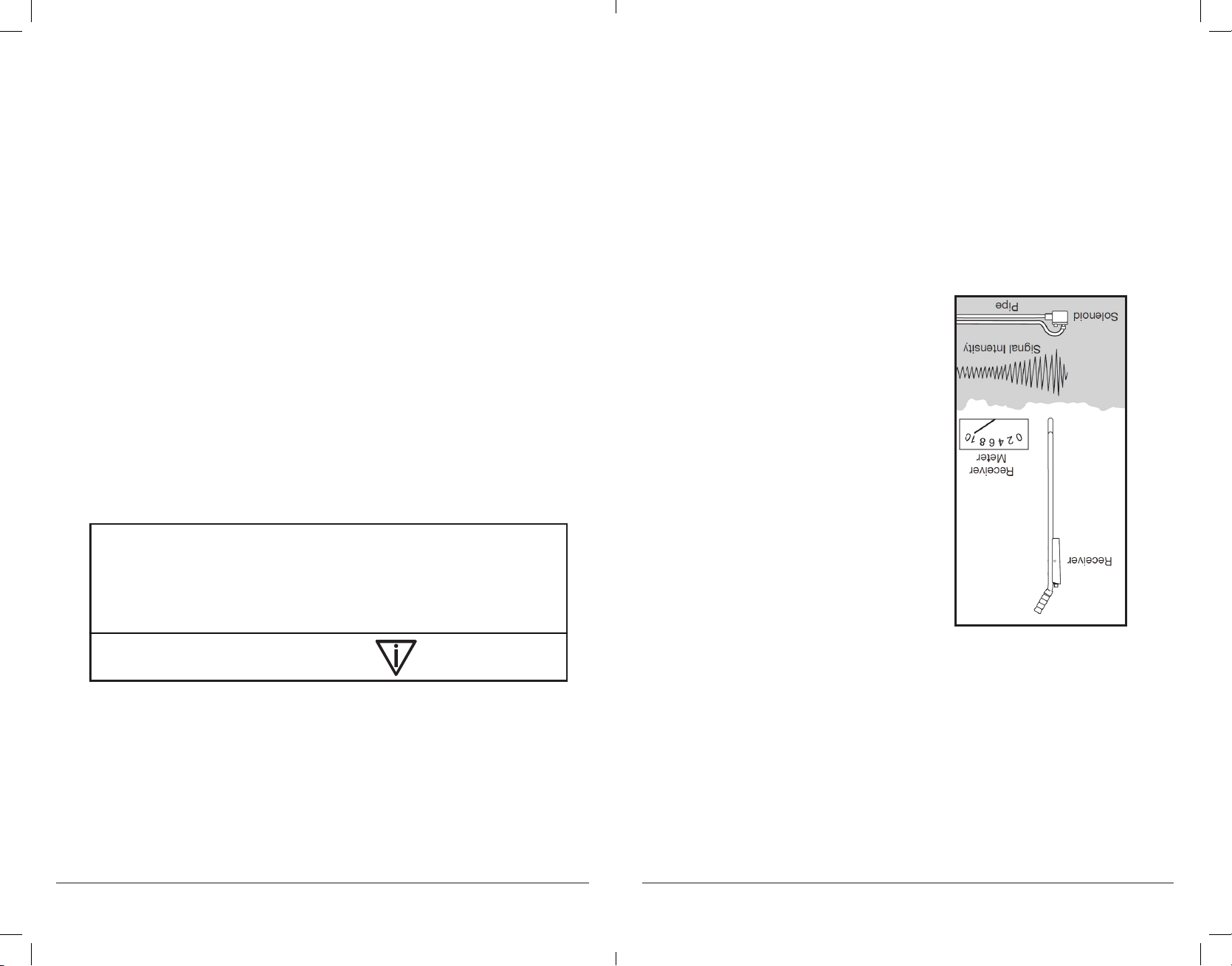
Determinación de la profundidad del cable
Para determinar la profundidad del cable, marque primero el suelo
directamente por encima de la ruta. Gire el receptor lateralmente
hacia la ruta e inclínelo 45°. Mueva el receptor para alejarlo de la
ruta, manteniendo la punta de 45° hasta detectar una respuesta
nula. Marque este punto. La profundidad es la distancia entre las
dos marcas. (Consulte la Figura 5)
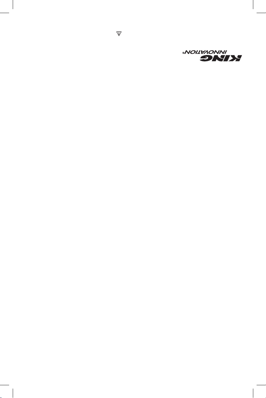
Proceso de localización de válvulas solenoide de dos tiempos
Las válvulas de solenoide se pueden localizar siempre que todos
los cables que llevan a ellas estén intactos y el solenoide mismo
aún esté en buenas condiciones.
Paso 1
1. Configure el transmisor como en la “Sección de configuración”.
La respuesta nula estará presente hasta que pase por encima de
una válvula de solenoide y luego la señal se volverá sumamente
potente. Marque este punto. Verifique alrededor del punto
caliente para detectar una respuesta nula que salga de la
zona. Si la respuesta nula continúa, sígala y marque los puntos
calientes adicionales. (Consulte la Figura 6) Si solo se localiza
un punto caliente o una válvula, será la válvula en cuestión.
FIGURA 3: Localización del
extremo de un cable roto
FIGURA 4:
Localización de una
melladura del cable
FIGURA 5:
Determinación de la
profundidad

6
I
KING INNOVATION KING INNOVATION
I
7
KING 521MANUAL DE INSTRUCCIONES
FUNCIONAMIENTO
Localización de rutas de cables
Con la sonda orientada a tierra, camine completamente alrededor
de la ubicación del transmisor. Se detectará una ausencia de tono
o respuesta nula directamente por encima de la ruta del cable. El
movimiento hacia cualquier lado hará que aumente el volumen
de la intensidad de la señal sonora. Siga la respuesta nula para
determinar la ruta del cable. (Consulte la Figura 2).
Localización de roturas y melladuras de cables
Cuando se intenta localizar roturas y melladuras, se debe reducir
la sensibilidad del receptor al orientarlo en otro sentido hacia
cualquiera de los lados de la respuesta nula. Podrá apreciar la
carga en la intensidad de la señal de inmediato. No permita
que se estabilice el medidor ni que supere 10. Esto ayudará
significativamente para el proceso de localización de averías.
NOTA: El cable debe tener una ruta a tierra para ser localizado
con éxito. Estas rutas existen en la gran mayoría de todos
los cables directos enterrados debido a imperfecciones en el
aislamiento, melladuras y malos empalmes. De lo contrario,
cree una conectando a tierra el extremo remoto.
CONFIGURACIÓN
NOTA: El transmisor produce alta tensión. Apague el transmisor antes
de manipular los conductores de salida. Desconecte todos los cables al
localizar averías. Ponga la perilla selectora en la posición BATTERY TEST
(prueba de la batería). La lectura del medidor debe estar entre 8 y 10.
IMPORTANTE: Para garantizar que el transmisor esté produciendo una
señal óptima, conecte los conductores de color rojo y negro juntos y
encienda la unidad. Gire la perilla selectora hasta la posición n.° 5. La
aguja del medidor debería subir hasta al menos una lectura de 10.
1. Con el transmisor apagado, conecte el conductor de color rojo al cable que
se desea localizar y el conductor de color negro a una conexión a tierra en
buenas condiciones con la punta proporcionada. (Consulte la Figura 1)
2. Encienda el transmisor y empiece a girar la perilla selectora en el sentido
de las agujas del reloj. Después de salir de la posición BATTERY TEST
(prueba de las baterías) y pasar al n.° 1, la aguja del medidor bajará hasta
cerca de cero. Al aumentar la salida, la aguja subirá ligeramente con
cada avance. Pare cuando la lectura del medidor esté entre 4 y 8. Ahora
el transmisor está ajustado para alcanzar la máxima eficacia para este
trabajo. Si no se puede obtener una lectura de 4, vuelva a ubicar la punta
de tierra.
3. Enchufe el auricular opcional en el receptor si lo desea, encienda el
receptor y oriente la antena o el extremo de la sonda al transmisor. Se
debe escuchar un tono intermitente y se debe registrar una indicación en
el medidor del receptor.
NOTA: Pueden generarse tonos agudos procedentes del auricular si su cable
queda demasiado cerca de la antena del receptor o si la batería del receptor
tiene poca carga.
PRECAUCIÓN Peligro de descargas eléctricas:
No conecte el transmisor a ningún circuito activo de CA.
Si no se respetan las precauciones se pueden ocasionar lesiones y
dañar el instrumento.
FIGURA 1: Configuración del transmisor
FIGURA 2: Localización de rutas de cables

4
I
KING INNOVATION KING INNOVATION
I
5
KING 521MANUAL DE INSTRUCCIONES
INFORMACIÓN IMPORTANTE SOBRE SEGURIDAD
ADVERTENCIA
Peligro de descargas eléctricas. El contacto con circuitos que tienen
energía puede ocasionar lesiones graves o la muerte.
ADVERTENCIA
Peligro de descargas eléctricas:
• No exponga esta unidad a la lluvia o la humedad
• Use esta unidad únicamente para los fines para los cuales fue
diseñada por el fabricante, según se describen en el presente
manual. Cualquier otro uso puede anular la protección que
proporciona la unidad.
• Use conductores de prueba o accesorios que sean adecuados para
la aplicación. Consulte la categoría y la clasificación de voltaje del
conductor de prueba o el accesorio.
• Inspeccione los conductores de prueba o el accesorio antes
del uso. Deben estar limpios y secos, y el aislamiento debe
estar en buen estado.
• Antes de sacar la tapa de las baterías o la caja, extraiga los
conductores de prueba del circuito y apague la unidad.
Si no se respetan estas advertencias, se podrían ocasionar lesiones
graves o la muerte.
PRECAUCIÓN
Peligro de descargas eléctricas. No conecte el transmisor
a ningún circuito activo de CA.
Si no se respeta esta precaución, se pueden ocasionar
lesiones y dañar el instrumento.
PRECAUCIÓN
Peligro de descargas eléctricas. No intente reparar esta unidad.
Incluye piezas que no pueden ser reparadas por el usuario.
Si no se respeta esta precaución, se pueden ocasionar lesiones y
dañar el instrumento.
El Sistema localizador de cables y válvulas King 521 incluye:
1. Auriculares
2. Punta de tierra
3. Transmisor
4. Receptor
5. Estuche
6. Conductor de color negro
7. Conductor de color rojo
8. Perilla selectora
9. Interruptor on/off
(encendido/apagado)
10. Tapa de las baterías
1 2 3 4 5
6 7 8 9 10

2
I
KING INNOVATION KING INNOVATION
I
3
KING 521MANUAL DE INSTRUCCIONES
ÍNDICE
DESCRIPCIÓN..............................................................................2
SEGURIDAD.................................................................................2
OBJETIVO DE ESTE MANUAL......................................................2
INFORMACIÓN IMPORTANTE SOBRE SEGURIDAD....................3-4
IDENTIFICACIÓN.........................................................................5
CONFIGURACIÓN .......................................................................6
FUNCIONAMIENTO ....................................................................7-10
ESPECIFICACIONES .....................................................................11
MANTENIMIENTO.......................................................................11
CAMBIO DE LAS BATERÍAS .........................................................11
DESCRIPCIÓN
El Sistema localizador de cables y válvulas KING 521 King
Innovation es una herramienta de detección de problemas
y mantenimiento universal para localizar rutas de cables, su
profundidad, roturas de cables, grandes melladuras y
válvulas de solenoide.
SEGURIDAD
La seguridad es fundamental para el uso y el mantenimiento de
las herramientas y los equipos King Innovation. El manual de
instrucciones y cualquier marca en la herramienta proporcionan
información para evitar peligros y prácticas poco seguras
en relación con el uso de esta herramienta. Respete toda la
información sobre seguridad que se proporciona.
OBJETIVO DE ESTE MANUAL
Este manual de instrucciones está diseñado para familiarizar
a todo el personal con los procedimientos seguros de
funcionamiento y mantenimiento para el Sistema localizador
de cables y válvulas KING 521 King Innovation. Mantenga este
manual disponible para todo el personal.
CONSERVE ESTE MANUAL
INFORMACIÓN IMPORTANTE SOBRE SEGURIDAD
PELIGRO
Peligros inmediatos que, de no evitarse, OCASIONARÁN
lesiones graves o la muerte.
ADVERTENCIA
Peligros que, de no evitarse, PODRÍAN ocasionar lesiones graves
o la muerte.
PRECAUCIÓN
Peligros o prácticas poco seguras que, de no evitarse,
PUEDEN ocasionar lesiones o daños a los bienes.
ADVERTENCIA
Lea y entienda este material informativo antes de operar
o realizar el mantenimiento de este equipo.
Si no se entiende cómo operar de manera segura esta
herramienta, se podría provocar un accidente y ocasionar
lesiones graves o la muerte.
PELIGRO se reserva para condiciones y acciones que es
probable que ocasionen lesiones graves o fatales.
ADVERTENCIA se reserva para condiciones y acciones que
pueden ocasionar lesiones graves o fatales.
PRECAUCIÓN se reserva para condiciones y acciones que
pueden ocasionar lesiones o daños a los instrumentos.

MANUAL DE INSTRUCCIONES
KING 521 #42521
PRECAUCIÓN
Debe leer y entender todas las instrucciones y
la información de seguridad que se incluyen
en este manual antes de operar o realizar el
mantenimiento de esta herramienta.
SISTEMA LOCALIZADOR DE CABLES Y VÁLVULAS
This manual suits for next models
1
Table of contents
Other King Innovation Measuring Instrument manuals