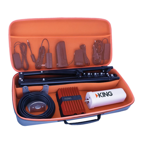
KING EXTEND PRO KX2000 User manual

KX2000
CELLULAR SIGNAL BOOSTER
User Manual
EXTENDPRO

Page 2
KC1347
110VAC/12VDC
Power Supply Instructions
Mounting
Bracket Ladder or Pole
Mounting Hardware
Signal Booster
with Bracket
Outside
Antenna
25’ Cable
Inside
Antenna
+ 13’ Cable
Pre-wire Enclosure
Connection Kit
Coax to Booster
Adapter
Short Coax
BEFORE YOU START
Read through this manual before installing
or operating the KING Extend Pro.
If you have any questions,
call KING Customer Service at (952) 345-8147.
! !
TABLE OF CONTENTS
PACKAGE CONTENTS.............................................................................. 2
OVERVIEW ................................................................................................. 3
IMPORTANT POINTS................................................................................. 3
COMPONENT LOCATIONS ....................................................................... 4
OUTSIDE ANTENNA MOUNTING OPTIONS ............................................ 5
INSTALLATION ....................................................................................... 6-7
SIGNAL BOOSTER LIGHT ........................................................................ 8
TROUBLESHOOTING................................................................................ 9
SAFETY GUIDELINES ............................................................................. 10
SPECIFICATIONS .................................................................................... 11
WARRANTY.............................................................................................. 12
PACKAGE CONTENTS

Page 3
Do not put sharp bends in coax cables.
This can reduce signal strength from the antenna.
Antennas connected to a booster create spheres of signal. When these
spheres overlap, a condition called oscillation occurs. Oscillation can be
thought of as noise, which causes the booster to scale down its power
or shut down to prevent damage. The best way to keep these spheres
of signal from overlapping is to maximize separation between the inside
and outside antennas.
IMPORTANT POINTS
OVERVIEW
The installer is responsible for determining the most appropriate
fasteners to secure the antenna bracket to the roof. Depending on
the roof material, fasteners such as lag screws, well nuts, sheet metal
screws, toggle bolts and T anchors may be used, and should always be
used in combination with a roof-compatible sealant.
The installer is responsible for properly securing the coax cable to the
roof (for example, cable ties and cable tie mounting pads).
Theinstallerisresponsibleforweatherproongallholesandfastener
heads with roof-compatible sealant.
You will need a drill and drill bit, roof-compatible sealant and appropriate
fasteners to install all components and wiring.
The KING Extend Pro is a cellular signal booster. It requires no additional
activation or service. You simply install it and connect power, register it with your
provider and it is ready to use.
KC1296
For more information on registering your booster with your provider, see:
Sprint & T-Mobile: https://www.t-mobile.com/support/coverage/register-a-signal-booster
Verizon Wireless: http://www.verizonwireless.com/wcms/consumer/register-signal-booster.html
AT&T: https://securec45.securewebsession.com/attsignalbooster.com/
U.S. Cellular: https://www.uscellular.com/support/fcc-booster-registration

Page 4
COMPONENT LOCATIONS
Outside Antenna
mounted to roof
KC1292
Metal
Obstruction
Booster
Inside Antenna
The outside antenna must be completely above the roof line.
Make sure the outside antenna does not exceed maximum vehicle height
restrictions.
Locate outside antenna as far from metal obstructions as possible.
The mounting bracket allows the outside antenna to be mounted directly to
the roof, or to a pole or ladder using the included pole mounting hardware.
Mount booster as far away from outside antenna as possible, but make sure
the 25 foot cable will still reach between the two.
A convenient place to mount the booster is to the inside back of a cabinet
near a 110 VAC power source. The booster can be oriented in any direction.
Place inside antenna as far away
from outside antenna as possible.
It is up to the installer to determine the best component locations.
Werecommendyoudoa“softinstall”rstbyplacingall
components in their chosen locations, completing the setup
instructions, and verifying the system works as desired.
(Route the cable through an open door or window for the
soft install.)
TIP

Page 5
OUTSIDE ANTENNA MOUNTING OPTIONS

Page 6
1. Fasten the outside antenna to the mounting bracket with the supplied
screws and washers (see page 5).
2. Connect the separate 25’ cable to the antenna (LARGE CONNECTOR).
3. Apply roof-compatible sealant around the areas where the bracket fasteners
will penetrate the roof.
TIP If your vehicle has a pre-wire enclosure on the roof, you can use
the included pre-wire kit for installation (see instructions in kit).
INSTALLATION
KC1296
AVOID SHARP BENDS WHEN ROUTING COAX!

Page 7
If using the included booster
mounting bracket, remove
the booster from the bracket.
Fasten bracket to wall, then
snap booster back into bracket.
TIP
4. Fasten bracket to roof. Make sure fastener holes and fastener heads are
properly sealed.
5. Route the cable to where it will enter the vehicle.
6. Drill an appropriately sized hole and feed the cable into the vehicle.
7. Seal the roof hole so it is completely waterproof (inside and outside).
Fasten cable to roof every 12-18 inches.
8. Inside, place the booster in desired location or install the booster to a wall.
Connect cable to the booster.
9. Connect inside antenna cable to booster. Place inside antenna in position
as far from outside antenna and booster as possible.
10. Plug booster into power source.
Make sure to avoid any cabling, pipes, etc. that may be
damaged by drilling in step 6.

Page 8
SIGNAL BOOSTER LIGHT
SOLID GREEN
This indicates your booster is functioning properly and there are no issues
with installation.
BLINKING RED, THEN SOLID GREEN
This indicates one or more of the booster bands has reduced power due to
a minor feedback loop condition called oscillation. This is a built-in safety
feature to prevent harmful interference with a nearby cell tower. If you are
already experiencing the desired signal boost, then no further adjustments
are necessary. If you are not experiencing the desired boost in coverage,
then refer to the troubleshooting section on the next page.
SOLID RED
This is due to a major oscillation (feedback) loop. This is a built-in safety
featurethatcausesabandtoshutotopreventharmfulinterferencewitha
nearby cell tower. Refer to the troubleshooting section on the next page.
LIGHT OFF
Ifthesignalboosterlightiso,verifyyourpowersupplyispluggedintoa
known good power source.
After making all connections, the signal booster will automatically power on and
the light will be green.
KC1295
Signal Booster
Light
®
Power Adapter Light
& ON/OFF Switch

Page 9
TROUBLESHOOTING
Need help? KING Customer Service: (952) 345-8147
FIXING BLINKING OR SOLID RED ISSUES
This section is only applicable if the signal booster light is red or blinking
red and you are not experiencing the desired signal boost.
1. Unplug the signal booster’s power supply.
2. Relocate the inside and outside antennas further away from each other.
The objective is to increase the separation between them, so that they will
not create the feedback condition discussed on page 3.
3. Plug power supply back in.
4. Monitor the indicator light on your signal booster. If after a few seconds of
“power on”, a solid blinking red light appears, repeat steps 1 through 3.
Increase the separation distance until the condition is corrected and/or
desired coverage area is achieved.
TIP
Increasing vertical separation between antennas
typically improves isolation better than increasing
horizontal separation.

Page 10
SAFETY GUIDELINES
Use only the power supply provided with this product. Use of any other
power supply may damage your equipment.
All inside antennas must be at least 18 inches from all active users.
Connecting the signal booster directly to the cell phone with use of an adapter
will damage the cell phone.
RF Safety Warning: Any antenna used with this device must be located at least 8
inches from all persons.
This is a CONSUMER device.
BEFORE USE, you MUST REGISTER THIS DEVICE with your wireless
provider and have your provider’s consent. Most wireless providers consent
to the use of signal boosters. Some providers may not consent to the use of
this device on their network. If you are unsure, contact your provider.
You MUST operate this device with approved antennas and cables as
speciedbythemanufacturer.AntennasMUST be installed at least 8 inches
from any person.
You MUST cease operating this device immediately if requested by the FCC
or licensed service provider.
WARNING: E911 location information may not be provided or may be
inaccurate for calls served by using this device.

Page 11
Each signal booster is individually tested and factory set to ensure FCC
compliance. The signal booster cannot be adjusted without factory
reprogramming or disabling the hardware. The signal booster will amplify, but not
alter incoming and outgoing signals in order to increase coverage of authorized
frequencybandsonly.Ifthesignalboosterisnotinuseforveminutes,it
will reduce gain until a signal is detected. If a detected signal is too high in a
frequency band, or if the signal booster detects an oscillation, the signal booster
willautomaticallyturnthepoweroonthatband.Foradetectedoscillation
the signal booster will automatically resume normal operation after a minimum
ofoneminute.Aftervesuchautomaticrestarts,anyproblematicbandsare
permanentlyshutountilthesignalboosterhasbeenmanuallyrestartedby
momentarily removing power from the signal booster. Noise power, gain, and
linearity are maintained by the signal booster’s microprocessor.
This device complies with Part 15 of FCC rules. Operation is subject to two
conditions: (1) This device may not cause harmful interference, and (2) this
device must accept any interference received, including interference that may
causeundesiredoperation.Changesormodicationsnotexpresslyapprovedby
weBoost could void the authority to operate this equipment.
FCC
Model
Connectors
Antenna Impedance
Frequency
Power output for single cell
phone (Uplink) dBm
Power output for single cell
phone (Downlink) dBm
Isolation
Power Requirements
Noise Figure
>90 dB
12 V, 1.8 A
KC1331
5 dB (nominal)
PWO460061
470061
SMB-Jack
50 Ohms
698-716 MHz, 728-756 MHz, 777-787 MHz, 824-894 MHz, 1850-1995 MHz, 1710-1755/2110-2155 MHz
700 MHz
Band 12/17
25.4
700 MHz
Band 13
25.6
1700 MHz
Band 4
26.7
800 MHz
Band 5
25.6
1900 MHz
Band 25/2
26.9
4.8 4.8 4.64.8 4.5
SPECIFICATIONS

Simply better, by design.
™
23696 Rev C © 2021 KING GDE000406_Rev001_11.01.21
This product is covered by U.S. patent(s) and pending application(s).
For patents go to: weboost.com/us/patents.
NOT AFFILIATED WITH WILSON ANTENNA
All trademarks are the sole property of their respective owners.
LIMITED WARRANTY
The KING Extend Pro is warranted for two (2) years against defects in workmanship and/or
materials. Should any trouble develop during the warranty period, contact KING at
(952) 345-8147. You must contact KING before the warranty period expires. The customer must
supply proof of purchase (such as a dated sales receipt) when requesting warranty service. If
the customer cannot supply proof of purchase, warranty period shall start 30 days after date of
manufacture.
Warranty claims for KING Signal Boosters are processed by Wilson Electronics (“Wilson”)
according to the warranty policy outlined below.
Warranty cases may be resolved by returning the product directly to the reseller
with a dated proof of purchase. Signal Boosters may also be returned directly to
the manufacturer at the consumer’s expense, with a dated proof of purchase and a
Returned Material Authorization (RMA) number supplied by Wilson. KING and Wilson
shall, at their option, either repair or replace the product.
This warranty does not apply to any Signal Boosters determined by KING or Wilson to
have been subjected to misuse, abuse, neglect, or mishandling that alters or damages
physical or electronic properties. Replacement products may include refurbished Wilson
productsthathavebeenrecertiedtoconformwithproductspecications.RMAnumbers
may be obtained by contacting KING Customer Support at (952) 345-8147.
In no event shall KING or Wilson be liable for any indirect, incidental, or consequential damages
from the sale or use of the product. This disclaimer applies both during and after the term of this
warranty.
KING disclaims liability for any implied warranties, including implied warranties of “merchantability”
and“tnessforaspecicpurpose,”afterthetermofthiswarranty.
Thiswarrantygivesyouspeciclegalrights,andyoumayalsohaveotherrights,whichvaryfrom
state to state. Some states do not allow the exclusion or limitation of incidental or consequential
damages, so the above limitation or exclusion may not apply to you. Some states do not allow
limitations on how long an implied warranty lasts, so the above limitation may not apply to you.
DISCLAIMER: The information provided is believed to be complete and accurate. However, no
responsibility is assumed by KING or Wilson for any business or personal losses arising from its
use, or for any infringements of patents or other rights of third parties that may result from its use.
This manual suits for next models
1
Table of contents
Other KING Extender manuals