Kingspan BFG 1 User manual

BioFicient 1-3
INSTALLATION MANUAL
BIOFICIENT 2-3 GRP – GRAVITY BIOFICIENT 1 MDPE – GRAVITY
BIOFICIENT 1 MDPE – IPS
Part Code Issue Description Date
017902 03 CC1282 February 2016

BioFicient 1-3
INSTALLATION MANUAL
2 3
Contents
Health and Safety Page 3
Desludging Page 4
Self Help Page 5
System Overview Page 6
BioFicient Checklist Page 7
Installaon Page 8-10
Control Panel Installaon Page 11
Start up Page 13

BioFicient 1-3
INSTALLATION MANUAL
2 3
HEALTH AND SAFETY
You must read these warnings carefully before installing or using the equipment. Should the equipment be transferred to a new
owner, always ensure that all relevant documents are supplied. Observe all hazard labels and take appropriate acon to avoid
exposure to the risks indicated. Take care to maintain correct posture, parcularly when liing. Use appropriate liing equipment
when necessary.
• Only experienced contractors should carry out installaon, following the guidelines.
• The unit should have a Pre-Service Agreement Inspecon by an approved engineer.
• A qualied electrician should carry out electrical work.
• Covers must be kept locked.
• Observe all hazard labels and take appropriate acon to avoid exposure
to the risks indicated.
CLOTHING
• We recommend the use of a dust mask and gloves when cung GRP components.
• Any person carrying out maintenance on the equipment should wear suitable protecve
clothing, including gloves.
WORKING AREA
• Ensure that the working area is adequately lit.
• Ensure that you are familiar with the safe working areas, accesses and that the area is adequately lit.
• Use only the designated access walkways. Do not walk on the cover or deep well safety mesh(es).
• Keep proper foong and balance at all mes. Avoid any sharp edges.
MAINTENANCE AND INSPECTION PROCEDURES
• Should you wish to inspect the operaon of the equipment, please observe all necessary precauons, includin g those listed below, which
apply to maintenance procedures.
• The power supply to the equipment must be isolated at the control panel(s) before liing the covers.
• If the equipment has to run with the covers o, all care must be taken to avoid contact with moving parts and electrical components or
conductors.
• Once power has been isolated, the control panel must be kept locked shut to avoid accidental re-connecon whilst work or inspecon is being
carried out.

Model BFG 1 BFG 2 BFG 3 BFG 4 BFG 5 BFG 6
Primary
Selement Tank
2000 Ltrs
(440 gal)
3600 Ltrs
(800 gal)
3600 Ltrs
(800 gals)
4700 Ltrs
(1040 gal)
6400 Ltrs
(1420 gal)
12300 Ltrs
(2730 gal)
Final
Selement Tank
54 Ltrs
(12 gal)
90 Ltrs
(20 gal)
90 Ltrs
(20 gal)
135 Ltrs
(30 gals)
180 Ltrs
(40 gal)
270 Ltrs
(60 gal)
Desludge Period 12 Months
Maximum
12 Months
Maximum
12 Months
Maximum
9 Months
Maximum
9 Months
Maximum
9 Months
Maximum
BioFicient 1-3
INSTALLATION MANUAL
45
DESLUDGING
• Desludging should be carried out by a licensed waste disposal contractor holding the relevant permits to transport and dispose
of sewage sludge.
Desludge Volumes

BioFicient 1-3
INSTALLATION MANUAL
45
SELF HELP
In order to minimize the need for dealing with emergency situaons we recommend that Treatment Plants have a Pre-service
Agreement Inspecon, and then is regularly serviced by us or an approved Service Engineers. Provided that your plant is
installed, operated correctly and serviced, you should not need to get into much – if any – self-help.
However, some of the most likely queson and answer situaons are listed below.
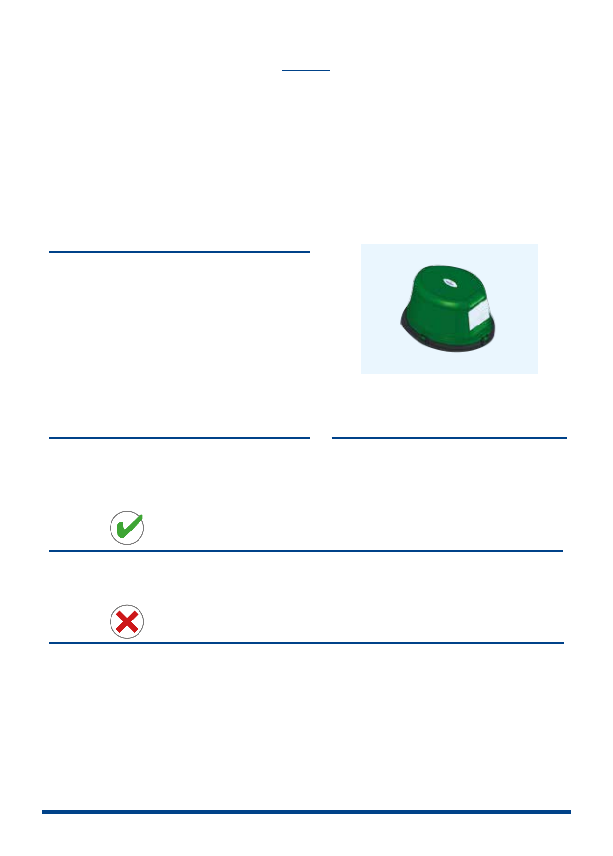
Blower
Blower Stopped:
• Check the unit is switched on, the incoming power supply
circuit and fuse.
Blower works but no water distribuon inside the plant:
• Check hose connecons.
• Check distributor heads.
• If the air li pipes are suspected to be blocked, call for service.
• Check regulang valve is not closed.
Plant ooding
• Check for blocked outlet system.
• If pumped outlet, check for pump operaon, check oats and
pump power supply.
Plant odour
• Check blower working.
• If blower working, plant probably needs desludging.
• Check vent circuit is clear.
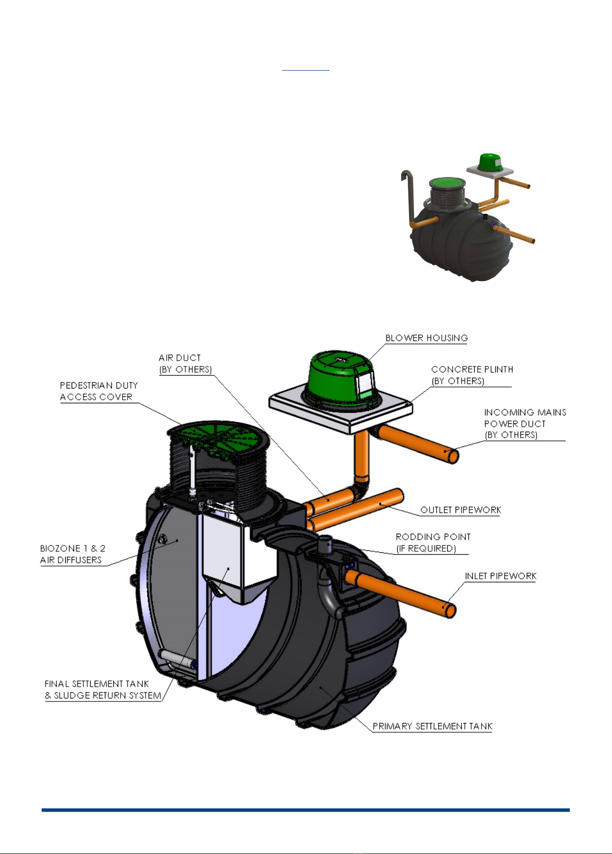
• Check that the air duct entering the blower housing has
been sealed with foam.
DO’s
Do take out a service agreement and let the experts look aer your plant.
Do contact us for advice if you have any cause for concern.
DON’TS
Don’t pump feed the plant without reference to us.
Don’t use a waste disposal unit as you will be adding to the biological load, and your system may not be large enough to cope
with the waste. If you are unsure please refer to our sales team for guidance.
Don’t throw any medicines down the toilet.
Don’t empty large quanes of bleach or similar cleaning reagents into the system.
Don’t empty cooking oil or similar down the sink.
Don’t cover the plant with soil material or prevent access for service and desludging.
Don’t apply a hose or jet wash to the biological lter unless specically advised to.
Don’t try to enter the plant
Don’t put sanitary towels, inconnence pads, nappies, tampons or other non-biodegradable items’ down the toilet.

BioFicient 1-3
INSTALLATION MANUAL
67
SYSTEM OVERVIEW
Pictorial representaon below indicates basic requirements for a standard system,
please note not all of the items required are supplied by Kingspan.

BioFicient 1-3
INSTALLATION MANUAL
67
BioFicient® CHECKLIST
The delivery paperwork will have 3 no. items listed; check that the Tank Code (Item 1) & Blower Assembly Code (Item 2) are the
same as the codes on the units delivered.
Example;
Top Level Product Code – BFP1GPPK
Item 1 – BFPTANK1GK (Tank Code)
Item 2 - BHBF1GOK (Blower Assembly Code)
Sewage Treatment Tank
Item 1
NB: Storage tanks vary in design and volume (6PE to 10PE) Please
check your parcular order and cross reference with relevant
sales drawing. (BioFicient MDPE Gravity shown)
13 mm Hose Coil - 15 Metres
Item 3
13 mm Hose required to connect from 1/2” Hose Connector in
Blower Housing to Sludge return Pipework located with the Tank).
(Suppiled inside Blower Housing Packaging)
Blower Housing Assembly
Item 2
The Blower Assembly consists of the Blower Unit, Control Panel
or Isolator, Solenoid Valve and associated pipework and ngs.
19 mm Hose Coil - 15 Metres
Item 4
19 mm Hose required to connect from 3/4” Hose Connector in
Blower Housing to Air Diuser Manifold located with the Tank).
(Suppiled inside Blower Housing Packaging)

Model
Diameter
/Width
(mm)
Length
(mm)
Inlet
Invert*
(mm)
Outlet
Invert**
(mm)
Installaon
depth**
(mm)
Biocient 1 1420 2500 500 600 1795
Biocient 2 1425 3760 500 600 1830
Biocient 3 1425 3760 500 600 1830
*BioFicient 1 Inverts available - 500 to 810, 1000 & 1500 mm
*BioFicient 2&3 Inverts available - 500, 1000 & 1500 mm
**Based on 500mm invert
BioFicient 1-3
INSTALLATION MANUAL
89
1. EXCAVATE A HOLE
Approximate dimensions
INSTALLATION
2. LAY CONCRETE BED 150-200 MM 3. LOWER UNIT ONTO CONCRETE
Should not be lied with any water inside

Gravity Unit – Inlet Ø110mm uPVC Pipe – Outlet Ø110mm uPVC Pipe
IPS Unit - Inlet Ø110mm uPVC Pipe – Outlet Ø50mm O/D MDPE Pipe
BioFicient 1-3
INSTALLATION MANUAL
89
3. LOWER UNIT ONTO CONCRETE
Should not be lied with any water inside
4. BACKFILL AND LEVEL
1. Pour 300 mm of water into the tank,
2. Backll with pea gravel or similar. Pea gravel is reliant
on use of correct strapping and anchoring.
Wet site: Make sure the base is adequate to support the
weight of the tank and its contents. If the base is unstable
excavate an addional 250-300mm below the concrete
levels and ll up with compacted hard-core.
Check that the inlet and outlet orientaon is correct
and that the unit is level.
Water levels always higher than backll
5. REMOVE TEMPORARY COVERS AND
CONNECT INLET AND OUTLET PIPEWORK 6. CONTINUE TO BACKFILL

BioFicient 1-3
INSTALLATION MANUAL
10 11
Fuse 5 A
Discharge pump
Fuse 3,15 A
Motor drive
TB1
Discharge Pump/ Solenoid Valve
Phase (red)
on « 1 »
Neutral (black)
on « 2 »
and Ground
(if applicable)
TB3
Blower
Phase (red)
on « 5 »
Neutral (black)
on « 6 »
and Ground
TB6
High water level
detector.
Wire1 (red)
on « 11 »
Wire 2 (black)
no connection
Wire 3 on « 12 »
(if applicable)
TB7
Remote beacon
Phase (red)
on « 16 »
Neutral (white)
on «17 »
and Ground (black)
on « 18 »
(if applicable)
CONTROL PANEL INSTALLATION
7. VENTING
To be vented locally at the plant

BioFicient 1-3
INSTALLATION MANUAL
10 11
HLA Bracket
Final
Settlement Tank
CONTROL PANEL INSTALLATION
BioFicient® IPS HLA
1. Remove the loose oat located in the blower housing.
2. Thread the oat cable through the gland in the HLA bracket xed to the Final Selement Tank in the plant.
3. Posion boom of the oat 200mm from top of the FST and ghten gland to secure the oat cable.

BioFicient 1-3
INSTALLATION MANUAL
12 13
Product Required Gland Feed through Gland Hole
number Terminate to connecon
Mains power supply M20 1
Integral discharge pump power cable M20 21&2
Sludge Return Solenoid Cable M20 31&2
Blower power supply cable M20 4 5&6
High level alarm cable M12 7 11&12
Beacon M12 916, 17&18
1
1
1
2
2 4
3 5 6 8
7 9
CONTROL PANEL ENTRY POINTS DEPENDING ON THE EQUIPMENT SUPPLY
Full Load Current (Amps) / Electrical Consumpon
(Kwh)
Biocient 1 Biocient 2 Biocient 3
Blower 240 volt single phase 0.4 /1.27 0.5 /1.82 0.6 /1.82
COMPLETING THE INSTALLATION
1. Plug the lead from the baery into the small white socket in the top right corner of the PCB marked “BATTERY HEADER”.
2. Power & Pressure Failure Detecon System (where applicable) - Using a small screwdriver, push switch 11 to the ON posion.
3. Installaon of High Level Alarm (where applicable) - Remove the link in the terminal blocks between connecons 11 & 12 (TB6) before inserng cables. Using a suitable
M12 gland, feed the high level alarm oat cable through Gland Hole 7 and terminate to connecon 11 & 12 (TB6) – Red to 11 & Black to 12.
1 - Pumped discharge only
2 - See Fig.1 below
Fig.1 Sludge Return Solenoid

BioFicient 1-3
INSTALLATION MANUAL
12 13
CONTROL PANEL ENTRY POINTS DEPENDING ON THE EQUIPMENT SUPPLY
SLUDGE RETURN SOLENOID RUN AND PAUSE TIME SETTING
FAULT CODES AND FUSES
CODE FAULT CONDITION FUSE Amp
F1 No power to the unit Customer Fuse box N/A
F2 The blower pressure has failed N/A N/A
F3 The high level alarm has acvated (where ed) N/A N/A
F4 The fuse to the motor has failed F3 3.15
F5 The fuse to the discharge pump has failed (where ed) F1 5.0
F6 The fuse to the chemical dosing pump has failed (where ed) F4 0.25
F7 The fuse to the recirculaon pump has failed (where ed) F2 5.0
F8 The loss of rotaon alarm has been acvated (not applicable) N/A N/A
- -
The unit has had a fault which has now corrected itself
(Flashing le and right - Baery charging
Flashing le only - Baery charged)
N/A N/A
All fuses are Time Lag HBC 20mm type
The mer should be factory set at the correct sengs

BioFicient 1-3
INSTALLATION MANUAL
14 15
We recommend that
the unit has a Pre-Service
Agreement Inspecon
by an approved engineer.
Once the unit has been
installed it should be le
lled with water.
START UP
NOTES

BioFicient 1-3
INSTALLATION MANUAL
14 15
NOTES

Kingspan Environmental Ltd
Unit 1, Derryboy Road
Carnbane Industrial Estate Newry,
BT35 6QH
Newry
GB T: 084 48 46 0500
NI T: 028 30 25 4077
IRL T: 048 30 25 4077
www.kingspanenviro.com
Kingspan Environmental
College Rd North
HP22 5EW
Aston Clinton, Aylesbury
This manual suits for next models
5
Table of contents
Other Kingspan Storage manuals
Popular Storage manuals by other brands

Hitachi
Hitachi Virtual Storage Platform G200 quick start

Intel
Intel SS4200-E - Entry Storage System NAS Server Technical product specification

Tower Hobbies
Tower Hobbies EASY TOTE manual

Freecom
Freecom USB-CARD manual

Sony
Sony USM32A, USM64A, USM128A, USM256A operating instructions

Infortrend
Infortrend EonStor GS Series installation guide

MXI Security
MXI Security stealth hd bio quick start guide

DANE-ELEC
DANE-ELEC SO EXTREME SSD MIGRATION KIT Getting started guide

HyLoft
HyLoft TireLoft 01030 Assembly instructions

Qsan Technology
Qsan Technology XCubeNAS XN7004R owner's manual

AmbiCom
AmbiCom WL54-CF Specifications

HIK VISION
HIK VISION 81 Series Quick operation guide