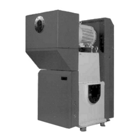
KINNEY KT-300 User manual

Kinney®
Single-Stage, Triplex Rotary Piston Pump
KT™ SERIES
Models
KT150 KT300 KT500 KT850
OPERATOR’S MANUAL
WARNING: Do Not Operate Before Reading Manual
Operator’s Manual: KT™ Series Single-Stage, Triplex Rotary Piston Pump
Manual 1843 Rev C p/n 001843 0000
800.825.6937 | www.kinneyvacuum.com
Original Instructions

Disclaimer Statement:
All information, illustrations and specications in this manual are based on the latest infor-
mation available at the time of publishing. The illustrations used in this manual are intended
as representative reference views only. Products are under a continuous improvement policy.
Thus, information, illustrations and/or specications to explain and or exemplify a product,
service or maintenance improvement may be changed at any time without notice.
Rights Reserved Statement:
No part of this publication may be reproduced or used in any form by any means - graphic,
electronic or mechanical, including photocopying, recording, taping or information storage
and retrieval systems - without the written permission of Kinney®.
Product information and specications subject to change.

i
Table of Contents
Manual 1843 Rev C p/n 001843 0000
Table of Contents
Introduction .................................................................................. 1
Applicable Documentation ................................................................... 1
Scope of Manual................................................................................... 1
Conventions and Data Plate ....................................................... 2
Graphic Conventions in this Manual ..................................................... 2
Data Plate.............................................................................................. 3
Lifting ............................................................................................ 5
Description ................................................................................... 6
Principle of Operation........................................................................... 6
Specifications........................................................................................ 7
Materials of Construction...................................................................... 8
Installation .................................................................................... 9
General ................................................................................................. 9
Safety ......................................................................................... 9
Lubrication .......................................................................................... 10
Hazards Associated With Breakdown or Ignition of
Lubrication ............................................................................... 11
Filling the Pump With Oil .......................................................... 11
Location .............................................................................................. 11
Foundation................................................................................ 11

ii
Table of Contents
Manual 1843 Rev C p/n 001843 0000
Installing the Vibramounts........................................................ 11
Piping Connections............................................................................. 12
Main Piping .............................................................................. 12
Hazards Associated With Hazardous Process Fluids.............. 14
Cooling Water........................................................................... 14
Vacuum Gauges ................................................................................. 16
Operation .................................................................................... 17
General ............................................................................................... 17
Electrical Connections ............................................................. 17
Pre-start Checks ................................................................................. 18
Pump Warm-up ................................................................................... 18
Pump Shutdown.................................................................................. 19
Handling Large Quantities of Water ................................................... 19
Gas Ballast.......................................................................................... 19
Stalling ................................................................................................ 20
Pump Leaks ........................................................................................ 20
Checking Pump Performance .................................................. 21
Checking Process Equipment.................................................. 21
Maintenance ............................................................................... 23
General ............................................................................................... 23
Periodic Maintenance ......................................................................... 23
Changing the Oil ...................................................................... 24
Oil Contamination..................................................................... 24
Replacement Parts ............................................................................. 24
Recommended Oil ................................................................... 25
Factory Service and Repair ................................................................ 25

iii
Table of Contents
Manual 1843 Rev C p/n 001843 0000
Repair Instructions .................................................................... 26
General ............................................................................................... 26
Discharge Valves...................................................................... 26
Shaft Seal Assembly ........................................................................... 27
V-Belt Drive.......................................................................................... 28
Disassembly........................................................................................ 29
Assembly ............................................................................................ 30
Troubleshooting......................................................................... 32
KT Series Part Number Designations ................................................. 34
Parts List..................................................................................... 36
Pump Assembly – KT-150, KT-300, KT-500, KT-850 ........................... 36
Pump Parts List – KT-150, KT-300, KT-500, KT-850 ............................ 37
Pump Assembly – KT-150C, KT-300D, KT-500D, KT-850D.................. 38
Pump Parts List – KT-150C, KT-300D, KT-500D, KT-850D .................. 39
Filter System Kit Parts List – KT-150C................................................. 42
Filter System Kit Parts List – KT-150C................................................. 43
Filter System Kit Parts List – KT-150C................................................. 44
Filter System Kit Parts List – KT-150C................................................. 45
Warranty – Vacuum Products ................................................... 46
Operating Data Form / Product Registration........................... 47

iv
Table of Contents
Manual 1843 Rev C p/n 001843 0000

1
Manual 1843 Rev C p/n 001843 0000
CONGRATULATIONS on the purchase of a new
Kinney®KT™ Single-Stage, Triplex Rotary Piston
Vacuum Pump. Please examine the pump for
shipping damage, and if any damage is found,
report it immediately to the carrier. If the pump is to
be installed at a later date, make sure it is stored
in a clean, dry location and rotated regularly. Make
sure covers are kept on all openings. If pump is
stored outdoors, be sure to protect it from weather
and corrosion.
This manual applies to Kinney Vacuum models
KT-150, KT-300, KT-500 and KT-850. Become
thoroughly familiar with these instructions before
attempting to install, operate or repair this unit.
Consult Kinney when problems arise that cannot
be resolved after reading this manual. Always
include pump nameplate information when ordering
parts or components.
Kinney KT vacuum pumps are built to exacting
standards and, if properly installed and maintained,
will provide many years of reliable service. Read
and follow every step of these instructions when
installing and maintaining the pump.
WARNING
!
Serious injury can result from operating or
repairing this machine without rst reading the
service manual and taking adequate safety
precautions.
OTE:N Record the pump model and serial
numbers in the OPERATING DATA form
on the inside back cover of this manual.
Use this identication on any replacement
part orders, or if service or application
assistance is required.
APPLICABLE DOCUMENTATION
The applicable documents associated with this
manual are:
• EN 1012-1:1996 - Compressors and vacuum
pumps - Safety Requirements - Part 2: Vacuum
Pumps
SCOPE OF MANUAL
The scope of this manual includes the KT Series
rotary piston pumps.
INTRODUCTION
01

2
Manual 1843 Rev C p/n 001843 0000
GRAPHIC CONVENTIONS IN THIS
MANUAL
This manual is the result of a risk assessment
according to the applicable documents referenced
in Applicable Documentation on page 1. The
following are hazard levels referenced within this
manual:
DANGER
!
Indicates a hazardous situation that, if not
avoided, will result in death or serious injury.
WARNING
!
Indicates a hazardous situation that, if not
avoided, could result in death or serious
injury.
CAUTION
!
Indicates a hazardous situation that, if not
avoided, could result in minor or moderate
injury.
Indicates a situation that can cause damage
to the engine, personal property, and/or
the environment or cause the equipment to
operate improperly.
OTE:N Indicates a procedure, practice, or
condition that should be followed in
order for the equipment to function in the
manner intended.
CAUTION
!
Read manual before operation
or bodily harm may result.
Attention should be given to the
safety related sections of this
manual.
CONVENTIONS AND DATA PLATE
02

3
02
Conventions and Data Plate
Manual 1843 Rev C p/n 001843 0000
DATA PLATE
WARNINGWARNING CAUTION CAUTION
Hearing protection
re
q
uired.
Do not touch hot
surfaces.
ASUehtniedaM7396-528)008(
READ INSTRUCTION MANUAL BEFORE OPERATION OR BODILY HARM MAY RESULT
Keep body & clothing away
from machine openings.
Do not operate without
g
uards in
p
lace.
REBMUNLAIRESREBMUNLEDOM YEARMAWP
MAX RPM
4840 West Kearney Street
Springfield, Missouri USA 65803
Figure 2-1 – General Operation and Symbols on Data Plate
The following information is contained on the data
plate:
WARNING
!
Keep body & clothing away
from machine.
During operation, keep body
and clothing away from inlet
and outlet of the pump.
WARNING
!
Do not operate without guards
in place. Assure that the guards
are in place and secure prior to
operation.
CAUTION
!
Hearing protection is required
while the pump is in operation.
At ultimate pressure noise
levels are 75 dBA, however
due to process or installation
conditions noise levels may be
higher.
CAUTION
!
Do not touch hot surfaces.
Do not touch the vacuum pump
while it is in operation and
assure that the pump is cool
before touching, when not in
operation.

4
02
Conventions and Data Plate
Manual 1843 Rev C p/n 001843 0000
MODEL NUMBER: The specific model of the pum
SERIAL NUMBER: Unique to each pump. Use with any service issues and with any contact with
the manufacturer.
YEAR: Year of manufacture
MAX RPM: Maximum RPM at which the pump can be operated
This manual describes instructions and precautions to be observed in the
handling and maintenance of Kinney® KT™ Single-Stage, Triplex Rotary
Piston Vacuum Pumps. It is strongly recommended that those who operate
or maintain the pump read this manual carefully prior to pump operation, to
ensure personal safety and pump life.

5
Manual 1843 Rev C p/n 001843 0000
WARNING
!
The vacuum pump must be handled using
an appropriate device such as a fork truck
or appropriate lifting device. See Table 4-1
on page 7 for approximate weights. Care
should be taken to assure pump does not
over-turn during handling and installation.
CAUTION
!
DO NOT LIFT THE VACUUM PUMP BY THE
MOTOR.
Lift the vacuum pump using both eyebolts
directly attached to the top of the pump
separator housing, or with both fork truck forks
underneath the pump.
LIFTING
03

6
Manual 1843 Rev C p/n 001843 0000
The KT Series pumps covered by this manual
have an oil circulating pump to provide adequate
lubrication at all pressures, including atmosphere.
The vacuum pump has three cams and pistons
pumping in parallel, driven by a common shaft.
The cams are positioned on the shaft so they
dynamically balance moving parts. This balancing
technique applied to the Rotary Piston Principle,
developed by Kinney, virtually eliminates vibration.
Figure 4-1 – General Operation Principle shows
a cross section of the pump with the pistons
being driven by the cams and revolving within the
cylinder.
PRINCIPLE OF OPERATION
Gas is drawn into the pump through a common
inlet, channeled to the three piston slides and
into the space behind the pistons as they rotate.
The gas ahead of the pistons is compressed and
forced out of the discharge valves. As the gas is
forced through the pump, sealing oil is mixed with
the discharged gas and the discharged mixture is
channeled into the separator, which is located in
the reservoir. There the gas is separated from the
oil. Sealing and lubricating oil is provided by the
oil pump, which is mounted on the non-drive head
and driven by direct coupling to the vacuum pump
drive shaft. The oil pump provides forced feed oil
circulation at all operating pressures, including
atmosphere.
All models have a channeled drive shaft with an
opening at each cam to distribute oil through the
pump.
Oil is taken from the reservoir at a point some
distance above the reservoir bottom. This provides
an area for impurities to collect for draining.
1.
KEY
AIR/OIL SEPARATOR
2. OIL LEVEL
3. CONNECTION FOR OPTIONAL TEMPERATURE SWITCH
4. CONNECTION FOR TEMPERATURE GAUGE
5. CONNECTION FOR “SCUM” TAKE-OFF
6. PUMP INLET
7. SLIDE PIN
8. WATER COOLING JACKET
9. (FAR SIDE) COOLING JACKET DRAIN (1 OF 2)
10. VIBRAMOUNTS
11. DISCHARGE VALVE
12. GAS BALLAST VALVE
13. OIL DRAIN
14. PISTON SLIDE
15. SHAFT
16. PISTON
17. CAM
18. CONNECTION FOR OPTIONAL HEATER
19. COOLING JACKET DRAIN (2 OF 2)
1
2
3
4
5
6
7
8
9
10
11
12
13
14
15
16
17
18
18
19
Figure 4-1 – General Operation Principle
DESCRIPTION
04

7
04
Description
Manual 1843 Rev C p/n 001843 0000
Figure 4-2 – Triplex Arrangement
SPECIFICATIONS
UNIT KT-150 KT-300 KT-500 KT-850
Nominal Displacement cfm (m3/h) 150 (255) 300 (510) 490 (840) 780 (1325)
Motor Power HP 7.5 15 30 40
Rotation Speed RPM 1055 870 721 581
Oil Capacity (Total/Refill U.S. gal (L) 6/5 (23/19) 10/8.5
(38/32)
15/12.5
(57/47)
28/25
(106/95)
Cooling Water at 60°F (16°C) gpm (L/min) 1 (4) 1.5 (6) 2.5 (9) 3.5 (13)
Cooling Water Inlet Connection NPT 1/4 in. 3/8 in. 3/8 in. 3/8 in.
Suction Connection 150 lb ANSI
Flanged 3 in. 4 in. 6 in. 8 in.
Discharge Connection 150 lb ANSI
Flanged 2 in. 3 in. 4 in. 5 in.
Height Without Oil Mist Eliminator Inches (mm) 43 (1092) 51 (1295) 63 (1600) 71 (1803)
Floor Space Required Inches (mm) 24 × 26
(609 × 660)
27 × 34
(686 × 864)
34 × 38
(864 × 965)
38 × 49
(965 × 1245)
Weight lb (kg) 800 (363) 1,525 (692) 2,625 (1,191) 4,175 (1,894)
Ultimate Pressure microns 10 10 10 10
Noise Level (Typical at .1 Torr)* dBA 71 72 73 75
* Noise level may vary based upon motor selection.
Table 4-1 – Specifications
WARNING
!
Do not exceed maximum rotation speed
(RPM) as stated in Table 4-1.

8
04
Description
Manual 1843 Rev C p/n 001843 0000
MATERIALS OF CONSTRUCTION
HOUSINGS AND CYLINDER: Cast iron
PISTONS, CAMS, SLIDE PINS: Cast iron
SHAFT: AISI 1144 Stress-proof
SHAFT SEALS: Cast iron/Carbon/Viton®
BALLAST/CHECK VALVE: Brass/bronze

9
Manual 1843 Rev C p/n 001843 0000
GENERAL
KT pumps should always be operated with the
pump in a vertical and level position. KT pumps
should never be installed in a horizontal or angled
position. Pump assembly should be placed on a
foundation and should be supported evenly. Pump
assembly should be leveled to within 0.02 in. (0.5
mm) in any 3.28 ft (1 m).
Any time the vacuum pump will be stored for an
extended period of time (longer than 6 months),
make sure it is protected from corrosion by
preparing it for long-term storage.
1. Fill the separator housing to halfway in the
sight glass with the recommended oil for the
pump.
2. Close off the pump suction and discharge
connections using blind flanges with gaskets.
The oil fill connection should be plugged tightl ,
and the oil drain valve should also be plugged,
to avoid accidental loss of oil.
3. Drain the water jacket and any other heat
exchangers containing water.
4. Leave the water inlet and outlet connections
unplugged and remove the drain plug from the
bottom of the cooling jacket.
5. Reduce the tension on the drive belts by
lowering the motor mounting plate.
6. Rotate the shaft of both pump and motor
several revolutions by hand at least every 3 to
6 months to keep the lubrication and shaft load
distributed in the bearings and seals.
7. For pumps that have been in service, contact
the factory for complete instructions.
Safety
DANGER
!
Internal and external rotating
parts of the pump and driving
equipment can produce
serious physical injuries. The
pump should never be run
with the inlet or discharge
piping removed. If it becomes
necessary to inspect the
rotating parts of the pump or to
change the belt, be absolutely
sure that all power to the motor
controls has been shut off, the
motor controls are locked out,
and properly tagged before
proceeding.
WARNING
!
Vacuum pump housing
and associated piping or
accessories may become hot
enough to cause major skin
burns on contact as a result of
process conditions.
INSTALLATION
05

10
05
Installation
Manual 1843 Rev C p/n 001843 0000
WARNING
!
Use lockout / tagout procedures to disable the
electrical energy source before any service or
work is done on the vacuum pumps.
CAUTION
!
Avoid extended exposure in
close proximity to machinery
with high intensity noise levels.
Wear adequate ear protection.
CAUTION
!
Other potential hazards to safety may also be
associated with operation of this equipment.
All personnel working in or passing through
the area should be warned by signs and
trained to exercise adequate general safety
precautions.
Use proper care and good procedures in
handling, lifting, installing, operating, and
maintaining the equipment.
LUBRICATION
The KINNEY KT Pump is lubricated by a
pressurized oil system. A positive displacement
pump generates oil pressure. KT vacuum pumps
use KV100 oil. KV100 is used for factory testing
and the initial charge is shipped along with the
pump. It is necessary to use this oil to maximize
pump life, achieve design intents and maintain
full warranty. Contact the factory for review of a
desired substitute or inert oils.
The lubricating gear pump is mounted on the
closed head and is driven directly by the vacuum
pump shaft. Failure of the gear pump may be
detected by reduced oil pressure, deteriorating
performance, noise, unusually high discharge or
oil reservoir temperature and lower temperature
of oil line tubing. The tubing should be nearly the
same as the oil temperature, or 145 to 190°F
(63 to 87°C). If using the high oil temperature
switch (water miser) option, it should be set at
190°F (88°C) when used with standard KV100 oil.
Consult factory if higher discharge temperatures
are required to avoid contamination of oil.
KT pumps are equipped with an oil pressure gauge
that should indicate at least 20 PSIG (1.4 bar)
(KT500 and KT850) or 25 PSIG (1.7 bar) (KT150
and KT300).
KT pumps may include an optional oil filtration
system. With this system, the filter indicator gauge
(red/green) may be in the red until the oil warms to
140°F - this is normal. If gauge needle is in the red
after the oil warms to 140°F, replace the filte .
WARNING
!
Never attempt to change or add lubrication
while the pump is running. Failure to heed
this warning could result in damage to the
equipment or personal injury.
WARNING
!
Properly dispose of spent lubricants. Refer
to the manufacturer of the lubricant and any
applicable regulations to ensure proper and
safe disposal.
These pumps do not have a bypass valve on
the oil pump and pressure may exceed 150
PSIG (10 bar) on cold start up.
If the oil level is too low, bearings and seals will
be damaged as a result of improper lubrication.

11
05
Installation
Manual 1843 Rev C p/n 001843 0000
Hazards Associated With Breakdown
or Ignition of Lubrication
DANGER
!
There is a risk associated
with the lubrication media
breaking down and resulting
in a hazardous uid or vapor.
There may also be a hazard
associated with the ignition of
the lubrication media. Refer to
the lubrication manufacture’s
applicable instruction for safety
precautions.
Filling the Pump With Oil
For initial oil filling and the first filling after t
pump has been disassembled, the quantity of oil
to be placed in the reservoir is one gallon less
than shown in the specifications. One gallon is
required in the suction port as outlined in Suction
Manifolding on page 12.
Use oil recommended by Kinney and see the
specifications for the quantity of oil required to fil
the pump. Remove the oil fill plug at the top of
the separator housing and add oil until the level
reaches the top of the sight gauge. The level
will drop to below mid-center of the gauge once
the pump is operated at blank-off and the oil is
distributed. With the pump shut off, add or drain oil
as necessary to keep the oil level (at blank-off) 3/8
in. (1 cm) up from the bottom of the glass. The oil
level changes with operating pressure, reaching
the lowest level at blank-off.
CAUTION
!
Do not overll the pump as excess oil will
be blown out the discharge during the high
pressure operation of the pump.
LOCATION
The pump should be mounted on a flat, level
surface. If installing outdoors, please ensure the
motor, painting, peripheral equipment, parts, etc.
are suitable for outdoor operation. There should be
enough space around the pump to allow for safe
maintenance work and periodic inspections. This
includes, at a minimum, the ability to access oil fill
and drain locations, view the oil level glass and the
oil temperature and pressure gauges.
Foundation
The foundation for the pump assembly should be
flat and level, and have adequate load-bearing
capacity. The pump and its base frame, peripheral
equipment and piping should be installed after the
foundation concrete has been cured. Systematized
pumps and frames should be leveled and secured
prior to operation.
Installing the Vibramounts
KT pumps are supplied with vibramounts, which
enable them to run quietly and vibration-free.
The pump can be operated on any floor that will
support its weight. The pump must be installed
on the vibramounts and flexible connectors
fitted in suction, discharge, water and electrical
connections. It is not necessary to bolt the pump to
the floo .

12
05
Installation
Manual 1843 Rev C p/n 001843 0000
If the studs are not already installed into the
vibramounts, thread the short end into the top of
the mount (smaller diameter) up to the spacer
portion of the stud.
The vibramount attachment holes are the four open
threaded holes in the flanged edges of the cylinde ,
in line with the bottom plate/cylinder bolts, just in
from each corner of the pump.
WARNING
!
Do not use the four unthreaded holes, these
are used for shipment only.
With the pump lifted off the ground, thread the
vibramounts with studs into the vibramount
attachment holes until contact is made between
the top of the vibramount and the cylinder bottom
plate, and the foot location is parallel to the pump
shaft. See Pump Assembly – KT-150, KT-
300, KT-500, KT-850 on page 36 for KT850
vibramount locations, as the vibramounts are not
interchangeable on this model.
Carefully set the pump down squarely on the mounts
when installing the pump in operating position.
If the KT pump was supplied as a part of a system,
with the vibramounts pre-installed, ensure that
any shipping retention bolts or spacer tubes are
removed before startup. To avoid damage to
the pump, it should be solely supported by the
vibramounts when in operation.
PIPING CONNECTIONS
Manifolding should be no smaller than the pump
connections in oder to minimize restrictions to gas
flo . Accurately align the mating flanges to the inlet
and discharge manifolding to prevent distortion of
the pump housing.
WARNING
!
Pipe loading on the pump should be
negligible as pipe loading can cause
distortion of the pump. Use proper supports
and pipe hangers to assure that there is no
loading.
Main Piping
Suction Manifolding
Inlet manifolding should be sized and designed
with four objectives in mind:
• To avoid gas flow restrictions
• To prevent pump fluids from entering the
process chamber.
• To protect the pump from ingesting particulate
matter.
• To allow proper venting of the pump and suction
manifold.
Under normal conditions, the diameter of the
manifolding should not be less than the diameter of
the pump connection, and the pipe length should
be kept to a minimum.
Oil may splash from inside the pump through the
suction port, so the suction line must be designed
to prevent oil from collecting there and draining
back to the system or process. See Figure 5-1
for recommended arrangement as a guide for
fabricating inlet manifolding.
Proper standard inlet manifolding is available
from Kinney as a factory-installed or aftermarket
accessory.
VACUUM
GAUGE
VACUUM
GAUGE
ISOLATION
VALVE
AIR VENT
VALVE
SHUT OFF
VALVE
PUMP
SUCTION
FLANGE
TRAP
DRAIN
TO
SYSTEM
RIGHT
ANGLE
FLEXIBLE
CONNECTOR
Figure 5-1 – Detailed Manifold Arrangement

13
05
Installation
Manual 1843 Rev C p/n 001843 0000
In all cases, the inlet manifolding should include
a 90° flanged elbow vertically oriented upward to
retain pump oil at low pressures, an isolation valve,
a flex connecto , and a vent valve.
A flexible connection should be installed in
the suction manifold to provide freedom for
vibramounts. The vacuum piping must be well-
aligned with the pump connections so as not to
place a strain on the piping.
A vacuum isolation valve should be installed
adjacent to the suction port to be used for leak-
checking, shutting down the system or blanking-off
the pump. This will also allow the system to be
kept under vacuum while the pump is not running,
or to keep the pump operating while the system is
at atmospheric pressure.
Gauge connections should be provided on both
sides of the isolation valve. With this arrangement,
it is possible to check the system or the pump
for leaks or ultimate vacuum level performance
without disconnecting the vacuum piping.
Provisions for gauge installation and any other
drilling in the piping must be made prior to piping
installation; otherwise, drilling particles entering the
piping could be entrained into the pump.
Before connecting the suction manifolding,
distribute 4 quarts of oil over the three slide
pins by reaching through the suction port with a
container and pouring oil directly onto the slide
pins. Then rotate the pump by hand a minimum of
two revolutions to distribute the oil throughout the
pump interior.
During the initial operation and as long thereafter
as necessary, install a fine mesh screen across
the inlet connection to prevent abrasive or solid
particles left in the line from being sucked into the
pump. This screen can be removed when particles
no longer accumulate. If particles continue to
accumulate, install a filter in the line upstream of
the pump.
Proper Venting
The vacuum pump must be properly vented
to ensure all oil is removed from the pumping
chamber before the pump is turned off. Also, the
suction line must be properly vented to ensure oil
does not migrate into the process chamber.
Recommended vent valve sizes:
KT-150 = 0.75 inch KT-300 = 1.0 inch
KT-500 = 1.5 inches KT-850 = 2.0 inches
The vent valve must be open for at least 10
seconds before the pump is turned off to remove
all oil from the pumping chamber.
Discharge Manifolding
Discharge manifolding should be sized and
designed to prevent the following:
• Return of oil mist condensate to the pump
• Oil loss
• Oil mist in the discharged gas
Under normal conditions, the diameter of the
manifolding should not be less than the diameter
of the pump connection, and pipe length should
be kept to a minimum to avoid increased back
pressure.
The installation of an oil mist eliminator on the
discharge is recommended for all applications
(as shown in Figure 5-3). Oil that collects in the
eliminator should be returned to the pump. The
oil return kit will drain oil back into the separator
housing when the pump is operating at low
pressure or when the pump is stopped. If the pump
is to operate continuously, or normal operating
pressure is between 10 Torr (13 mbar) and 150 Torr
(200 mbar), the oil return should be connected to
the gas ballast as shown in Figure 5-2. If over
150 Torr (200 mbar), the oil return should be
connected to the pump inlet.

14
05
Installation
Manual 1843 Rev C p/n 001843 0000
DISCHARGE
OIL
MIST
ELIMINA
TOR
OIL
RETURN
LINE
GAS
BALLAST
ASSEMBL
Y
Figure 5-2 – Oil Return to the Gas Ballast Valve
OME DISCHARGE
CONNECTION
FIBER OUTER
SHELL (ELEMENT)
SATURATED
ZONE
OIL COLLECTS
AT BOTTOM PRESSURE
GAUGE OR
PRESSURE
RELIEF VALVE
FIBER INNER
SHELL
(ELEMENT)
ALTERNATIVE TO THE
PUMP OIL RESERVOIR
OR GAS BALLAST
VALVE
OIL DRAIN
CONNECTION
OIL DRAIN
CHECK
VALVE
TOP COVER
GASKET
OIL MIST
FROM THE
PUMP (1)
OIL RETURN
CONNECTION
Figure 5-3 – Oil Mist Eliminator
It may be necessary to pipe the pump exhaust
fumes away from the pump area, such as
outdoors. If this is done, the piping must be
arranged to prevent line condensation from
returning to the pump. A flexible connector should
be fitted in the discharge line to provide freedom
for the vibramounts.
Hazards Associated With Hazardous
Process Fluids
DANGER
!
It shall be the responsibility
of the installer to ensure that
piping is adequate, sealing
between pipe joints is adequate
for the process uids and
proper process and pressure
protection devices are in place.
It is also the responsibility
of the installer to assure
that process gasses are not
vented in a manner that would
be hazardous. Refer to the
manufacturer of the process
media to assure that proper
safety precautions are in place.
Cooling Water
The cylinder cooling water jacket is shipped dry.
Fill the water jacket before starting the pump.
If an optional water flow modulating valve (water
miser) is fitted, the cylinder may take 20 minutes or
more to fill. The delay can be avoided by manually
lifting the spring to open the valve. For installation
of the valve, see Figure 5-4.
This manual suits for next models
8
Table of contents
Other KINNEY Water Pump manuals

KINNEY
KINNEY KVO Series User manual

KINNEY
KINNEY KD Series User manual

KINNEY
KINNEY KVA Series User manual

KINNEY
KINNEY KT SERIES Operating instructions

KINNEY
KINNEY KVC Series User manual
KINNEY
KINNEY KT-150 User manual

KINNEY
KINNEY KLRC40 User manual

KINNEY
KINNEY KT VFP Series Operating instructions

KINNEY
KINNEY KTC SERIES General instructions