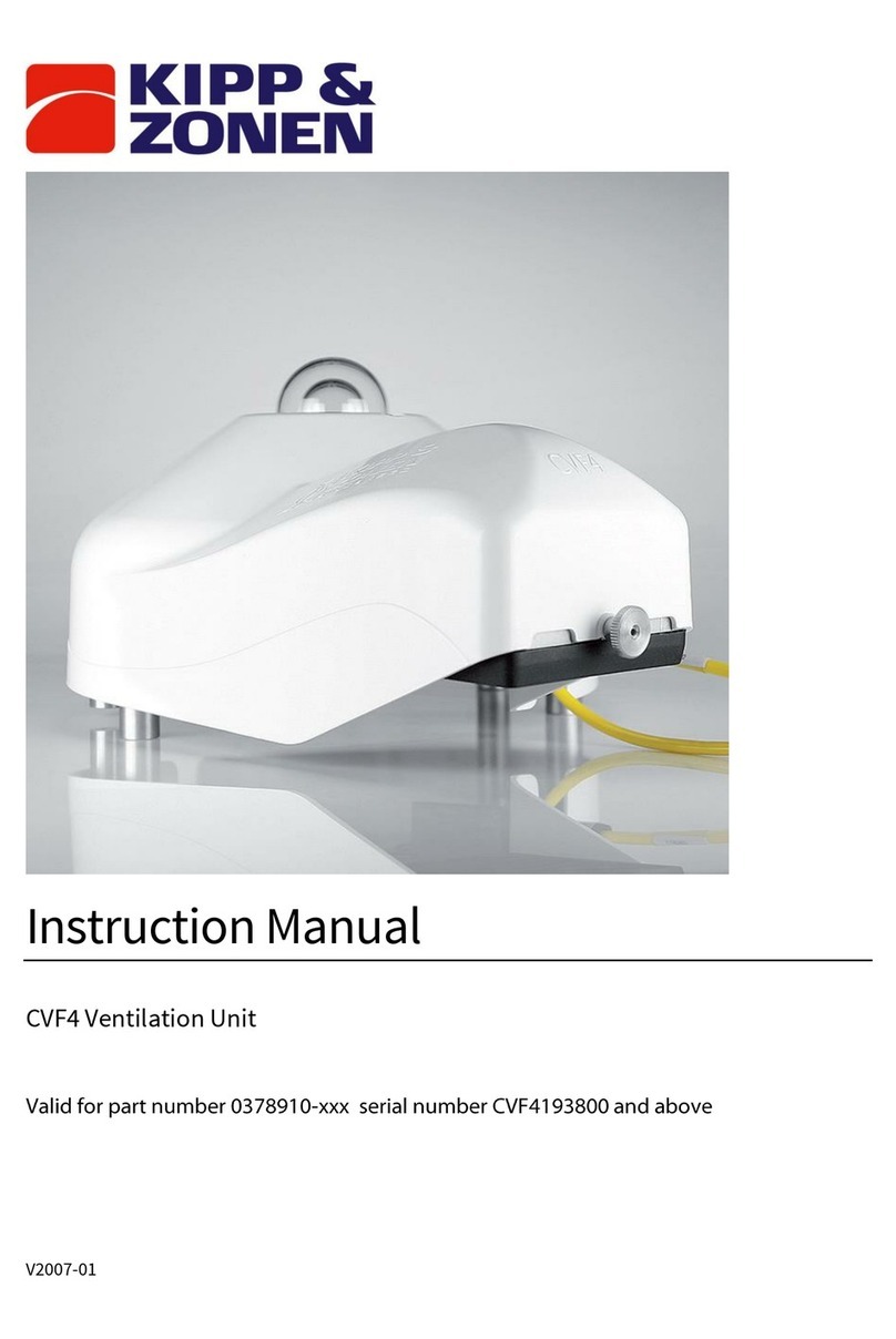
Kipp & Zonen CV 2 User manual

INSTRUCTION MANUAL
Kipp
Zonen
&
VENTILATION UNIT
2
0349 200

1
INSTRUCTION MANUAL CV 2
Reading this entire manual is recommended for full
understanding of the use of this product
The exclamation mark within an equilateral triangle is intended to alert the user
to the presence of important operating and maintenance instructions in the
literature accompanying the instrument.
Should you have any comments on the product or this manual we will be
pleased to receive them at:
Kipp & Zonen B.V.
Röntgenweg 1 2624 BD Delft Holland
P.O. Box 507 2600 AM Delft Holland
Phone +31 (0)15 2698000
Fax +31 (0)15 2620351
E-mail
Kipp & Zonen reserve the right to make changes in the specifications without
prior notice.
WARRANTY AND LIABILITY
Kipp & Zonen guarantees that the product delivered has been thoroughly
tested to ensure that it meets its published specifications. The warranty
included in the conditions of delivery is valid only if the product has been
installed and used according to the instructions supplied by Kipp & Zonen.
User made modifications can affect the validity of the CE declaration.
Kipp & Zonen shall in no event be liable for incidental or consequential
damages, including without limitation, lost profits, loss of income, loss of
business opportunities, loss of use and other related exposures, however
caused, arising from the faulty and incorrect use of the product.
COPYRIGHT©2004 KIPP & ZONEN
All rights reserved. No part of this publication may be reproduced, stored in a
retrieval system or transmitted in any form or by any means, without
permission in written form from the company.
Manual version 1203
IMPORTANT USER INFORMATION

2
INSTRUCTION MANUAL CV 2
Declaration of Conformity
According to EC guideline 89/336/EEC 73/23/EEC
We Kipp & Zonen B.V.
Röntgenweg 1
2624 BD Delft
Declare under our sole responsibility that the product
Type: CV 2
Name: Ventilation unit
To which this declaration relates is in conformity with the following standards
Imissions EN 50082-1 Group standard
Emissions EN 50081-1 Group standard
EN 55022
Safety standard IEC 1010-1
Following the provisions of the directive
B.A.H. Dieterink
President
KIPP & ZONEN B.V.

3
INSTRUCTION MANUAL CV 2
IMPORTANT USER INFORMATION......................................... 1
CE DECLARATION OF CONFORMITY .................................... 2
1. GENERAL INFORMATION........................................................ 5
2. DELIVERY COMPLETE VENTILATION SYSTEM CV 2........... 7
3. SPECIFICATIONS CV 2 ............................................................ 9
4. INSTALLATION OF THE CV 2 ................................................ 11
4.1 General..................................................................................... 11
4.2 Measuring global radiation....................................................... 12
4.3 Measuring diffuse radiation...................................................... 13
5. INSTALLATION OF THE POWER SUPPLY FOR CV 2.......... 15
6. MAINTENANCE AND OPERATING ........................................ 17
7. TROUBLE SHOOTING............................................................ 19
8. PART NUMBERS / SPARE PARTS / OPTIONS..................... 21
TABLE OF CONTENTS

4
INSTRUCTION MANUAL CV 2

5
INSTRUCTION MANUAL CV 2
1. GENERAL INFORMATION
The CV 2 ventilation unit is meant for ventilating solar radiation sensors and
can be used outdoors under all weather conditions. The CV 2 is available with
and without heater. An optional power supply can order separately.
The reliability and accuracy of solar radiation measurement can be improved
by using artificial ventilation.
The main advantages of ventilating are:
1. Prevention of precipitation of dew and frost which otherwise
would disturb the measurement.
2. Suppression of the infrared offset, which is produced e.g. by
cooling down of the glass domes under calm clear sky conditions.
Under extreme conditions, it can be necessary to heat the ventilation air. If the
temperature of the ventilation air does not exceed the temperature of ambient
air by 1 K, offset problems are not significant.
The ventilation system CV 2 is meant to be used with the Kipp & Zonen
pyranometers (CM 11, CM 6B, CM 21 and CM 22) and with radiation sensors
with equal dimensions like the pyrgeometers (CG 1 and CG 4) and the UV-
radiometers (CUVA 1, CUVB 1, CUV 3).
The CV 2 can be ordered with or without heater. The optional power supply
can be used for both versions.
The ventilator of the CV 2 must run continuously. The heating can be
connected for 5 or 10 Watt. Without heating the temperature of the instrument
is maintained near to that of ambient air.
The ventilation unit is suited for placement on the 2AP Tracking system.
The ventilation system does not prevent the dome to become filthy.
The ISO Technical Report 9901 "Solar Energy - Field Pyranometers
Recommended Practice For Use" contains an informative chapter on
ventilation systems in general.
GENERAL INFORMATION

6
INSTRUCTION MANUAL CV 2

7
INSTRUCTION MANUAL CV 2
2. DELIVERY COMPLETE VENTILATION SYSTEM CV 2
CV 2 with heater 0349 901
Power supply for CV 2 (with heater) 0349 401
2 x bolt M6 x 90 2146 824
2 x bolt M5 x 50 0015 620
2 x nylon insulator 2147 249
2 x special screw 0015 621
2 x nut M6 6464 006
2 x lock washer M6 6487 006
2 x washer M6 6476 506
Instruction manual 0349 200
DELIVERY COMPLETE VENTILATION SYSTEM CV 2

8
INSTRUCTION MANUAL CV 2

9
INSTRUCTION MANUAL CV 2
3. SPECIFICATIONS CV 2
Ventilation power 5 Watt continuously
Heating (optional) 5 and 10 Watt
Ambient operating temperature -30 to +70 ºC
Air temperature rise
caused by CV 2
< 0.25 K @ 0 Watt (blower only)
< 0.5 K @ 5 Watt (heater)
< 1 K @ 10 Watt (heater)
Offset caused by heater (10 W) < 1 W/m
2
using Pyranometer CM 11
Cable length 10 m.
Power required 12 Volt DC, 1,25 A (with 10 W heater)
Figure 3.1 CV 2 outline dimensions in mm
SPECIFICATIONS CV 2

10
INSTRUCTION MANUAL CV 2

11
INSTRUCTION MANUAL CV 2
4. INSTALLATION OF THE CV 2
4.1 General
The installation of a radiometer in the blower unit can be seen in figure 4.1.1
The radiometer feet have to be removed first.
The radiometer is mounted flat on the mounting plate inside the CV 2 with
the 2 special M5 x 50 screws and the 2 nylon insulator rings (all included in
delivery of CV 2)
Once the radiometer is mounted inside the ventilation unit, the CV 2 can be
levelled using the spirit level of the radiometer and the adjustable feet of the
CV 2. After levelling the CV 2 can be fixated to the floor or plate using the 2
M6 x 90 screws. The cable of the radiometer can be slit through the opening
of the side of the CV 2 base plate.
At this point the rubber ring can be mounted in the groove on the side of the
base plate. After that the cover can be put over the inner part of the CV 2
and the radiometer. The cover must be lowered until the narrow part of the
cover is over the rubber ring.
The rubber ring is covered with grease to prevent sticking to the inside of the
cover.
Mount the 2 special screws to lock the cover (figure 4.1.2).
Figure 4.1.1 Installation of a radiometer in the blower unit
INSTALLATION OF THE CV 2
Screw M5 x 50 (2x)
Nylon insulator (2x)
Rubber
ring
Cover

12
INSTRUCTION MANUAL CV 2
Figure 4.1.2 The 2 special screws to lock the cover.

13
INSTRUCTION MANUAL CV 2
4.2 Measuring global radiation
The blower unit can be installed on a flat plate, using the CV 2 levelling
screws. Figures 4.2.1 and 4.2.2 refer to this situation. If problems with snow
build-up are expected, a hole can be made in the plate directly under the
ventilator. Make sure this hole does not exceed Ø 120 mm!
Figure 4.2.1 Blower unit on a flat plate
Figure 4.2.2 Footprint of the CV 2 for mounting on a plate
200,8 mm
Screw M6 x 90 (2x)
Top view
(without cover)
Max. Ø 120 mm
M6 (2x)
INSTALLATION OF THE CV 2

14
INSTRUCTION MANUAL CV 2
4.3 Measuring diffuse radiation
The blower unit can be mounted on the Kipp & Zonen 2AP tracking system
(see figure 4.3.1)
No special precautions are necessary. Instead of the radiometer support the
CV 2 will give the radiometer the correct height. The mounting holes to fixate
the CV 2 are present on the 2AP mounting plate.
Further details on how to mount the CV 2, radiometer combination on the
tracker will be given in the 2AP manual.
Figure 4.3.1 CV 2 installed on Kipp & Zonen Solar Tracker
INSTALLATION OF THE CV 2

15
INSTRUCTION MANUAL CV 2
5. INSTALLATION OF THE POWER SUPPLY FOR CV 2
The optional power supply unit (figure 5.1) is meant for indoor installation only.
The dimensions are (W x D x H) 134 x 80 x 53,5 mm.
The power supply unit requires 115 or 230 VAC as input.
The output is 12 VDC at 2,5 A. Therefore when necessary this unit can supply
the power for two CV 2’s.
The power supply is a switching type that automatically adapts to the supplied
voltage. To connect the power supply to a normal mains outlet the changeable
mains connector can be selected from one of the following 4 supplied types:
•European style type
•UK style type
•USA style type
•Australian style type
Figure 5.1 Power supply unit for CV 2
INSTALLATION OF THE POWER SUPPLY FOR CV 2

16
INSTRUCTION MANUAL CV 2
The CV 2 has a 10 meter 4 wire shielded cable to connect to the power supply
The Connection between the CV 2 cable and the adapter cable can be made
with any standard connection terminal block (e.g. like the one that is used
inside the CV 2 connection box, see figure 5.2). The shield of the power supply
cable is connected to the base plate inside the CV 2.
Figure 5.2 Connection block inside the CV 2
The DC output from the power supply unit is marked with a red sleeve on
the + wire.
For activating the ventilator the blue wire has to be connected to the 0 Volt, the
red wire has to be connected to the + 12 Volt.
The heater also uses the common blue wire as 0 Volt and green/white as the
+ 12 Volt connection
When only the green or white is connected the heating power is 5 Watt.
When both green and white are connected the heating power is 10 Watt.
Because all resistors (R1 - R4) are mounted on a metal ring around the
ventilation shaft, the dissipated heat is equally spread over the opening.
Therefore it does not matter whether the green or white wire is used for 5-Watt
operation.
The need for heating strongly differs on local climatological circumstances.
Generally heating is advised during cold seasons when frost and dew can be
expected.
INSTALLATION OF THE POWER SUPPLY FOR CV 2

17
INSTRUCTION MANUAL CV 2
6. MAINTENANCE AND OPERATING
The ISO TR 9901 recommendations for maintenance and operation of
pyranometers must be observed.
The ventilator is meant to run continuously.
The operational state of the ventilator, of the heating elements, and of the air
ducts, must be checked regularly (see figure 6.1).
The air filter is located on the bottom of the CV 2. The filter can be checked
and changed by removing the cover from the filter by pulling it down with two
hands on both sides of the CV 2.
The filter has to be free of dust particles and holes. New air filters can be
ordered at Kipp & Zonen (see chapter 8).
After cleaning or renewal the filter can be placed in the filter cover. The letter
can be pressed upward on the ventilator.
The filter cover clicks on the ventilator.
Figure 6.1 Ventilator and filter unit
Ventilator
Filter cover
MAINTENANCE AND OPERATING

18
INSTRUCTION MANUAL CV 2

19
INSTRUCTION MANUAL CV 2
7. TROUBLE SHOOTING
Malfunction Cause Check
Ventilator and heater
don’t work Power failure Check 12 VDC or
check mains voltage
Electrical connections Check impedance
R1 to R4 = 4 x 15
Ω
Power supply Check voltage
Ventilator does not
work
Obstruction Check interior
See figure 5.2 and 6.1 for locations to check.
TROUBLE SHOOTING
Table of contents
Other Kipp & Zonen Fan manuals