Kisan Telecom LMR250R01 User manual

LMR250R01 Operating Manual
(FCC ID: T7MLMR250R01C1)
2012. .
Kisan Telecom

2 / 30
Kisan Telecom Confidential Proprietary
Content
IMPORTANT NOTE:..............................................................................................................................................................4
FCC RF Radiation Exposure Statement: ...................................................................................................................4
1. Introduction....................................................................................................................................................................5
1.1. General Introduction.....................................................................................................................................5
2. System Network Configuration............................................................................................................................5
2.1. Network configuration.................................................................................................................................5
3. System Specifications ................................................................................................................................................6
3.1. General Specifications..................................................................................................................................6
3.2. System specifications....................................................................................................................................7
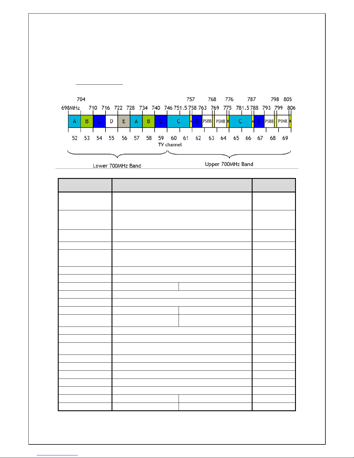
3.2.1. Frequency allocation........................................................................................................................7
3.2.2. System Specifications......................................................................................................................7
4. Mechanical Specifications .......................................................................................................................................8
4.1. LMR250R01C RU .............................................................................................................................................8
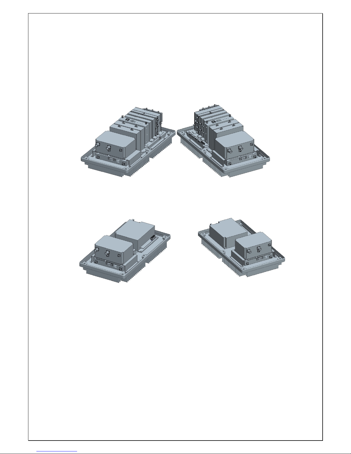
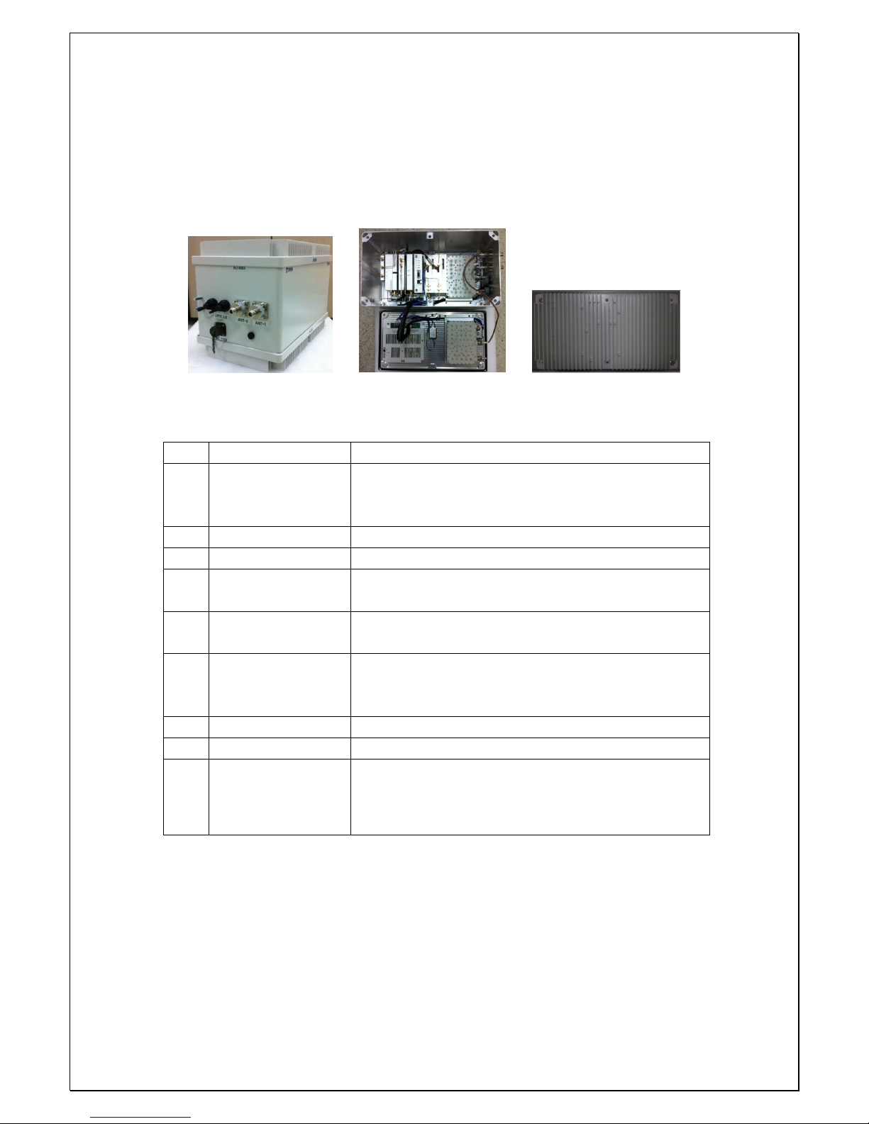
4.1.1. Mechanical Design............................................................................................................................8
4.1.2. Dimension ..........................................................................................................................................10
4.1.3. Mechanical Specification............................................................................................................10
4.1.4. Description of LMR250R01C RU.............................................................................................11
4.1.5. Port Configuration.........................................................................................................................12
4.1.6. Module Composition of RU......................................................................................................13
4.1.7. Function of Modules ....................................................................................................................14
5. Block Diagram............................................................................................................................................................17
6. Administration Program (RptMan-LMR250R01) ......................................................................................18
6.1. System Requirement ..................................................................................................................................18
6.2. Cable connection .........................................................................................................................................18
6.3. Screen ................................................................................................................................................................19
6.4. Status Display................................................................................................................................................20
6.5. Control Policy.................................................................................................................................................20
6.6. Menu ..................................................................................................................................................................20
6.7. Toolbar...............................................................................................................................................................21
6.8. Program operation......................................................................................................................................22
6.8.1. Initiating communication...........................................................................................................22
6.8.2. Disconnect..........................................................................................................................................22
6.8.3. LMR250R01 MHU Status Retrieval and Control.............................................................23

3 / 30
Kisan Telecom Confidential Proprietary
6.8.4. LMR250R01 RU Status Retrieval and Control..................................................................24
6.8.5. Firmware download ......................................................................................................................28
6.9. Additional features .....................................................................................................................................29
6.9.1. ASD (Auto Shutdown) Function .............................................................................................29
6.9.2. ALC (Auto Level Control) Function........................................................................................30

4 / 30
Kisan Telecom Confidential Proprietary
IMPORTANT NOTE:
FCC RF Radiation Exposure Statement:
This equipment complies with FCC RF radiation exposure limits set forth for an uncontrolled
environment. This equipment should be installed and operated with a minimum distance of 20
centimeters between the radiator and your body.This transmitter must not be co-located or operating
in conjunction with any other antenna or transmitter.

5 / 30
Kisan Telecom Confidential Proprietary
1. Introduction
1.1. General Introduction
As an equipment to clear RF shadows inevitably generated between the adjacent cells of
LTE, LMR250R01C supports LTE and effectively repeats the signals between mobile
terminals in weak coverage area and BTS.
This equipment is LTE MIMO Optical DAS that support 700MHz band simultaneously,
and it is designed to support LTE with MIMO.
This equipment provides the cost effective and flexible wireless solution to service
providers to improve quality of service for their subscribers.
The main objectives of LMR250R01C are as follows:
-Expansion of coverage
-Enhancement of service quality in areas such as tunnels or in-building
-Improvement in signal strength at places where the signal level is less than desired.
-Support dual bands of 700MHz.
-Support single mode of LTE band.
-RU power consumption and RU size optimization by built-in Crest Factor Reduction
(CFR) technology for the LTE signal.
2. System Network Configuration
2.1. Network configuration
LMR250R01C repeater is equipment to clear RF shadows, to fill coverage gaps existing
among the adjacent cells and to enhance the quality of service by extending coverage of
LTE.
The network configuration of LMR250R01C is the case that 1 MHU is connected with 1
RU by optical cables, and the coverage antennas of 700MHz are connected to RU, and
the link antennas of each band are connected to MHU.
System configuration
MHU Capacity: 1 Optical Branch/MHU
System Connection: single-mode Optical cable between MHU and RU
Optic Wavelength: 1570nm for FWD, 1330nm for RVS
Max loss of optic cable (between MHU and RU): 2 ~ 10dBo
2 coverage ANT ports for MIMO on RU. (Separate ANT Ports for 700MHz)

6 / 30
Kisan Telecom Confidential Proprietary
[Network Configuration of LTE MIMO Optical DAS with DB DAS]
3. System Specifications
3.1. General Specifications
Item LMR250R01
Enclosure Type Cabinet
W H D 471.7(H) X 263.4(W) X 304.8(D)mm Dimension
(mm) Weight 26 Kg
Power Supply 110-120Vac (Tolerance ±10%), 60Hz
Power Connector MS Connecter
RF In/Out Port N Type Female, a side part
Optic Connector Type SC, a side part
Optic Wavelength FWD: 1570nm / RVS: 1330nm
Operating Temperature -20℃ ~ 50℃
Environmental requirement
The repeater RU shall be operated in the temperature range of -20¡É ~ +50¡É.

7 / 30
Kisan Telecom Confidential Proprietary
3.2. System specifications
3.2.1. Frequency allocation
700MHz LTE Band
3.2.2. System Specifications
Item Specification Remarks
Tx Frequency Range A / B / Upper C band selection in 728 ~ 757MHz Refer to band
allocation
Rx Frequency Range A / B / Upper C band selection in 698 ~ 787MHz Refer to band
allocation
No of Carriers
Supported 1 CH LTE Carrier Max.
FWD Input Power -10 ~ 0dBm/total, -5dBm/total is recommended at MHU IN
FWD Output Power 40dBm/total for 700MHz RU ANT Port (MIMO0 / MIMO1)
RVS Input Power -50dBm/total max. at RU each ANT Port
RVS Output Power -20dBm/total max. at MHU each Rx ANT Port
System Gain FWD: 30dB ~ 50dB RVS:20dB ~ 30dB
FWD Spurious Comply to 3GPP, FCC regulation
RVS Noise Figure Comply to 17.5% of EVM by VzW test procedure
Gain Control Range FWD: 20dB by 1dB Step RVS: 20dB by 1dB Step RU OLC Gain
EVM (Error Vector
Magnitude) FWD: 12.5% RVS: 17.5%
Frequency Stability 0.01ppm
Pass-Band Ripple 1dB max. Any CH
System Delay Max. 6usec Without optical
cable
Tx0-Tx1 Isolation min. 40dBc
Tx-Rx Isolation 100dB min. @Between RU Tx Output and MHU Rx Output
Impedance 50 Ohm
VSWR 1.5 : 1 max. @ All input/output ports
Optical Wavelength FWD: 1570nm RVS: 1330nm
RF I/O Connector MHU: SMA-type Female RU: N-type Female

8 / 30
Kisan Telecom Confidential Proprietary
4. Mechanical Specifications
4.1. LMR250R01C RU
4.1.1. Mechanical Design
[RF SIDE]
[PSU SIDE]

9 / 30
Kisan Telecom Confidential Proprietary
[OUT SIDE 2D-Shape]
[OUT SIDE 3D-Shape]

10 / 30
Kisan Telecom Confidential Proprietary
4.1.2. Dimension
RU System picture and Size 471.7(H) X 263.4(W) X 304.8(D) mm
[OutSide] [Inner Side] [Heat Sink Side]
4.1.3. Mechanical Specification
No Item Description
1 Dimension & Weight
Dimension: 471.7(H) X 263.4(W) X 304.8(D) mm
(plinth included)
Weight: 26 Kg
2 Method of Cooling Natural convection (Heat-sink)
3 Door Locking Type More than 10-point on each side using bolt lock
4 Optic Connector Position: Cabinet inside
Connector type: SC/APC
5 ANT PORT located at the side of cabinet
Connector Type: N Type Female
6 Power Input
Power: 110-120Vac, 60Hz
Position: the side of cabinet
Connector: MS connecter
7 Ground TBD
8 Waterproof condition Comply to IPx6
9 Misc. Features
Easy to deploy
Strand type (i.e., telegraph pole)
Convectional Heat Sink

11 / 30
Kisan Telecom Confidential Proprietary
4.1.4. Description of LMR250R01C RU
[Forward path]
The LTE FWD MIMO0, MIMO1 and modem combined signals sent from the optic
module of MHU is first divided into MIMO0, MIMO1 and modem signals at RFMUX in
RU, then the FWD RF signals are amplified and filtered at the RFBS0 and RFBS1 module.
The modem signal is conveyed to CPU of NMS controller through FSK modem. LTE
signal is reduced by the Crest Factor passing through the CFR FPGA digital board inside
RFBS0 and RFBS1. This technology enables reduction of PAPR for LTE signal increasing
HPA efficiency. A higher efficiency HPA allows using a smaller enclosure with lower
power consumption while decreasing OPEX for the service provider.
The LTE RF signals from the RFBS modules is linearly amplified up to high power level
on HPA, passed through the Front-End Filter Unit, and finally transmitted through a
coverage antenna.
[Reverse Path]
LTE Rx signals incoming from coverage antennas are first passed by the Front-End
Filter Unit, amplified by a low noise and high gain amplifier, filtered in RRBS and
RRBS1, and combined with modem signal and 10MHz at combiner(RRCOM). The
combined signal is then transmitted to MHU through the optic module.

12 / 30
Kisan Telecom Confidential Proprietary
4.1.5. Port Configuration
No Item Description
1 AC INLET 110V AC Power Cable Connection Port
2 MIMO0 ANT Port MIMO0 ANT RF Cable Connection Port
3 MIMO1 ANT Port MIMO1 ANT RF Cable Connection Port
4 Optical Cable INLET Optic cable connection Inlet
5 Goretex

13 / 30
Kisan Telecom Confidential Proprietary
4.1.6. Module Composition of RU
Module operational voltage table
No Module Voltage Used Remarks
1 RFMUX
2 RF FWD Band Selector for MIMO0 (RFBS0) 5.5Vdc /6.5Vdc
3 RF FWD Band Selector for MIMO1 (RFBS1) 5.5Vdc /6.5Vdc
4 Slave Optical Transceiver Unit (SOU) 6.5Vdc
5 RF Modem (FSK Modem) 9Vdc
6 RU RVS COM for Signal combing (RRCOM)
7 RU RVS Band Selector for MIMO0 (RRBS0) 6.5Vdc
8 RU RVS Band Selector for MIMO1 (RRBS1) 6.5Vdc
9 TX HPA for MIMO0 29Vdc
10 TX HPA for MIMO1 29Vdc
11 FE-Duplexer(Front-End Filter Unit) for MIMO0
12 FE-Duplexer(Front-End Filter Unit) for MIMO1
13 PSU (AC-DC) AC 110V INPUT
14 NMS Controller 9Vdc
15 Back Board Ass’y 5.5Vdc /6.5Vdc /9Vdc

14 / 30
Kisan Telecom Confidential Proprietary
4.1.7. Function of Modules
No Module Description
1
[Divider]
Divides signals into RF and modem signals and
sends to RFBS/RFCHS and FSK modem.
2
[RFBS0]
Controls the gain of TX0 path, filters FWD band,
controls the crest factor of TX0 signal, and
performs the ALC function. Output of the module
is sent to HPA.
3
[RFBS1]
Controls the gain of TX1 path, filters FWD band,
controls the crest factor of TX1 signal, and
performs the ALC function. Output of the module
is sent to HPA.
4
[SOU]
Performs E/O (or O/E) conversion for FWD and
RVS signals.
Wavelength: LD 1330[nm], PD 1570[nm]
5
[FSK Modem]
Data modem for RU and MHU communication
RU → MHU frequency: 340MHz
MHU → RU frequency: 360MHz
6
[RRCOM]
Combines RX0, RX1 and Modem signals, and
provides the combined signal to optical module
in order to perform E/O conversion.
7
[RRBS0]
Amplifies RX0 signal by low noise high gain,
filters for the desirable band and controls the
RVS path gain of RU.
8
[RRBS1]
Amplifies RX1 signal by low noise high gain,
filters for the desirable band and controls the
RVS path gain of RU.

15 / 30
Kisan Telecom Confidential Proprietary
9
[TX HPA for MIMO0]
16Watt(42dBm) High power amplifier built-in
linearizer amplifies the TX0 signal to high power
level and sends to RU ANT through the MIMO0
FE-Duplexer.
10
[TX HPA for MIMO1]
16Watt(42dBm) High power amplifier built-in
linearizer amplifies the TX1 signal to high power
level and sends to RU ANT through the MIMO1
FE-Duplexer.
11
[FE-Duplexer for MIMO0]
Front end duplexer that passes through TX0 and
RX0 frequency bands.
12
[FE-Duplexer for MIMO1]
Front end duplexer that passes through TX1 and
RX1 frequency bands.
13
[PSU]
Converts AC 110V to DC 29V/9V/6.5V/5.5V, and
distributes the necessary power to each modules.
14
[NMS Controller]
Monitors the status of modules in RU and
controls the configurable parameters of the RU
modules.
15
[Interface BD]
Provides operating voltage and monitors/controls
signal to modules connected to interface B’D.
Also provides a connection port to communicate
with NMS B’D.

16 / 30
Kisan Telecom Confidential Proprietary
Power Distribution Diagram

17 / 30
Kisan Telecom Confidential Proprietary
5. Block Diagram

18 / 30
Kisan Telecom Confidential Proprietary
6. Administration Program (RptMan-LMR250R01)
Administration program (RptMan-LMR250R01) is a management program for LMR250R01
and provides status monitoring and controlling functions to users.
6.1. System Requirement
System: Desktop or laptop PC
OS: Windows XP or later version
Resolution: 1024 768 or more
Connection Cable: 9 pin serial cable (cross type)
6.2. Cable connection
The cable connection between repeater and PC (GUI program) is illustrated below.
The NMS port of MHU provides two ports; one is a D-sub port for local GUI. The other
is an Ethernet port for NOC (Network Operating Center).
Repeater
NMS
port
D-Sub 9Pin
Female
2
3
5
D-Sub 9Pin Male
2
3
5
D-Sub 9Pin Female
PC GUI
Program
2
3
5
Ethernet port for NOC
D-sub port for GUI

19 / 30
Kisan Telecom Confidential Proprietary
6.3. Screen
Section Description
Window Title
Displays the name of management program(GUI), i.e. RptMan-
LMR250R01.
Displays the type of equipment currently connected to the program
(MHU or RU).
Menu Bar
Presents working menu for operators.
It is associated with tool icons, which can activate the tool bar menus.
Toolbar
Presents icons (button type) for frequently used commands.
User-friendly icons are used.
Icons are activated or disabled as to the status of repeater.
Work Space
Status information and control functions are provided with a block
diagram view of MHU and RU.
Provides the working space for windows or dialogs.

20 / 30
Kisan Telecom Confidential Proprietary
6.4. Status Display
Status of repeater is displayed by LED’s and values.
LED
Alarm: / blinking indicates ALARM, indicates NORMAL
On/Off: ON, OFF
Exception) for HPA, is ON, is OFF
Value
Units are not displayed.
Value displayed in box ( )
Control
The shape of mouse cursor is changed to on controllable parameters.
The texts of controllable LED or values are displayed in BOLD font.
6.5. Control Policy
System parameter can only be controlled one at a time.
Click a control item (button) to bring up a control popup dialog window.
Once a dialog popup window is opened, it stays there for repeated control until user
closes the window.
6.6. Menu
Menu Sub Menu Function
Connect Establishes connection between PC(GUI) and repeater
Disconnect Disconnects connection between PC(GUI) and repeater
File
Exit Finishes admin program.
Power Table Presents RF/Optic power table
TC Table Presents temperature compensation table
Action
Image Compression Compress the firmware file (executable file of repeater)
Showing a control range
Configurable Item
Tar ge t E qui pme nt.
(MHU or RU)
Table of contents
Other Kisan Telecom Repeater manuals