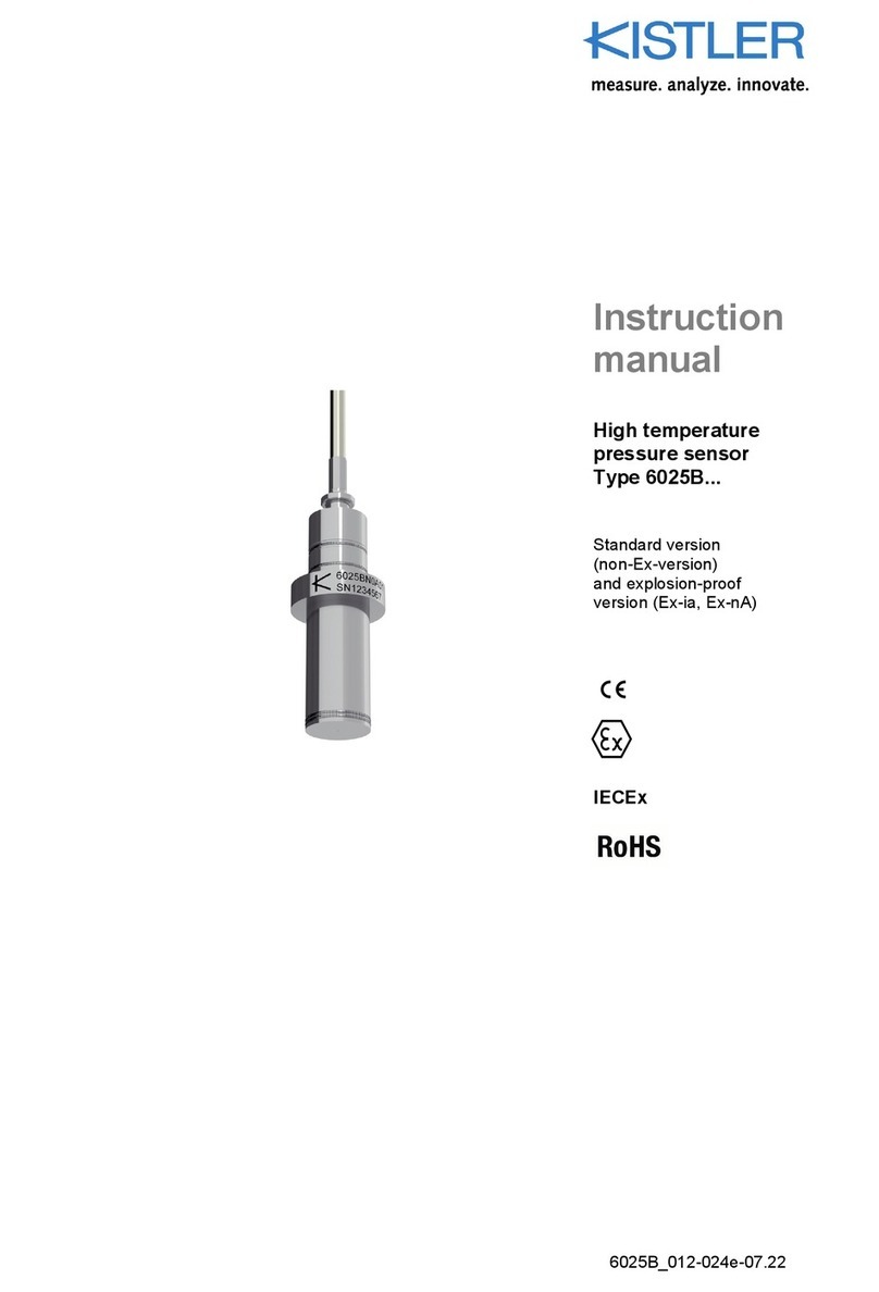
Kistler 2629DK User manual

Instruction
Manual
2629DK_002-819e-09.18
TDC Sensor System
Type 2629DK

Instruction
Manual
2629DK_002-819e-09.18
TDC Sensor System
Type 2629DK


Page 12629DK_002-819e-09.18
We thank you for choosing a Kistler quality product distin-
guished by technical innovation, precision and long life.
Information in this document is subject to change without
notice. Kistler reserves the right to change or improve its
products and make changes in the content without obliga-
tion to notify any person or organization of such changes
or improvements.
©2018 Kistler Group.
Kistler Group products are protected by various intellectual
property rights. For more details visit www.kistler.com.
The Kistler Group includes Kistler Holding AG and all its
subsidiaries in Europe, Asia, the Americas and Australia.
Kistler Group
Eulachstrasse 22
8408 Winterthur
Switzerland
Tel. +41 52 224 11 11
info@kistler.com
www.kistler.com
Foreword
Foreword

TDC Sensor System Type 2629DK
2629DK_002-819e-09.18Page 2
Content
1. Introduction .................................................................................................................................3
2. TDC Sensor System introduction..............................................................................................4
3. Important notes / protection of the instruments......................................................................5
3.1 For your safety....................................................................................................................5
3.2 Disposal instructions for electronic equipment ...................................................................5
4. Structure of the TDC Sensor System........................................................................................6
5. Installation of the TDC Sensor System.....................................................................................7
5.1 Mounting the TDC probe ....................................................................................................7
6. Installation of the TDC electronic............................................................................................10
7. TDC determination with TDC Sensor System ........................................................................12
8. Principle of capacitive TDC determination.............................................................................13
9. Technical data ...........................................................................................................................14
9.1 TDCprobewithintegratedsignalamplier,Type2629D10/2629D11 ..............................14
9.2 TDC electronic, Type 2629D20.........................................................................................15
10. Warranty.....................................................................................................................................16
11. Appendix....................................................................................................................................17
Total pages 17

Introduction
Page 32629DK_002-819e-09.18
1. Introduction
Please take the time to thoroughly read this instruction
manual. It will help you with the installation, maintenance,
and use of this product.
To the extent permitted by law Kistler does not accept any
liability if this instruction manual is not followed or pro-
ducts other than those listed under Accessories are used.
Kistler offers a wide range of products for use in measu-
ring technology:
Piezoelectric sensors for measuring force, torque,
strain, pressure, acceleration, shock, vibration and
acoustic-emission
Strain gage sensor systems for measuring force and
moment
Piezoresistive pressure sensors and transmitters
Signal conditioners, indicators and calibrators
Electronic control and monitoring systems as well as
softwareforspecicmeasurementapplications
Data transmission modules (telemetry)
Kistler also develops and produces measuring solutions
fortheapplicationeldsengines,vehicles,manufacturing,
plastics and biomechanics sectors.
Our product and application brochures will provide you
with an overview of our product range. Detailed data
sheets are available for almost all products.
If you need additional help beyond what can be found
either online or in this manual, please contact Kistler‘s
extensive support organization.

TDC Sensor System Type 2629DK
2629DK_002-819e-09.18Page 4
2. TDC Sensor System introduction
The TDC Sensor System is used for the dynamic deter-
mination of the top dead centre position (TDC) in recipro-
cating piston engines. It consists of the TDC probe with
integratedsignalamplierandTDCelectronic.Thedevice
is installed in the nozzle holder or spark plug hole of the
engine.
In general, the TDC calibration process can be executed
via a motored engine mode, or by using the pressure sig-
nalfromanunredcylinder(oftenachievedbyinterrupt-
ingignition/fuelinthesparkignitionengineorbydisabling
fuel injection in a Diesel engine).
It is important to note that knowledge of the exact top
dead centre position is of great importance for investiga-
ting energy conversion processes occurring inside engi-
nes. This is due to the fact that all measurements are re-
corded against crank angle and with respect to TDC.
With some thermodynamic quantities such as mean indi-
cated pressure (IMEP), a deviation of only 0,1° crank ang-
le from the true top dead location will result in an error of
approximately1%inthenalIMEPvalue.
If, after studying these instructions, there are particular
questions, which you wish to have answered, then the
worldwide Kistler customer service is available to you. lt is
also competent to advise you on how to deal with applica-
tion-specicproblems.

Importantnotes/protectionoftheinstruments
Page 52629DK_002-819e-09.18
3. Important notes / protection of the instruments
It is essential for your personal safety when working with
the TDC Sensor System that you read the following ins-
tructions carefully and follow them. This will then ensure
long-term, hazard-free and fault-free operation of the in-
strument.
3.1 For your safety
This instrument has left the factory in a perfectly safe con-
dition. ln order to maintain this condition and to ensure
hazard-free operation, the user must comply with the user
operating instructions and the information and warning
notes contained in them and/or those printed on the in-
strument.
Additionally, local safety regulations concerning the hand-
ling and use of electrical and electronic equipment must
be observed.
Should there be a suspicion that safe operation will be no
longer possible, then the instrument must be shut down
and made safe against accidental start-up.
It must be assumed that safe operation is no longer pos-
sible.
when the instrument shows visible signs of damage,
when the instrument is no longer functioning properly,
If, according to the criteria listed above, safe and hazard-
free operation of the instrument can no longer be assu-
med as being assured, then the instrument must be im-
mediately returned to Kistler for repair.
3.2 Disposal instructions for electronic equipment
Do not discard old electronic devices in municipal trash.
For disposal at end of life, please return this product to
an authorized local electronic waste disposal service
or contact the nearest Kistler sales ofce for return
instructions.

TDC Sensor System Type 2629DK
2629DK_002-819e-09.18Page 6
4. Structure of the TDC Sensor System
The TDC Sensor System consists of
TDCprobewithintegratedsignalamplier
TDC electronic
Mains cable
Cable for TDC probe
Installation adapters
Instrument rod and adjuster rings
This system produces a capacitive displacement current
as the measuring signal, which is a function of the piston
movement and thus of the crank angle (see chapter 8).
TheTDCsignalamplierisintegratedintheTDCprobe.It
converts the position-dependent TDC probe capacitance
into a voltage signal. This can be connected, over a dis-
tance of up to 10 m, to the TDC electronic.
TDC probe
Fig. 1: TDC probe positioned in engine
The TDC electronic provides an output at a BNC socket
(voltage). The signal output is normally recorded against
crank angle position and then can be evaluated to de-
termine the exact TDC position. This process requires a
crank angle encoder and a combustion analysis system
(e.g. KiBox) for the purpose of recording and evaluating
the TDC signal.

Installation of the TDC Sensor System
Page 72629DK_002-819e-09.18
5. Installation of the TDC Sensor System
Install the measuring set-up, described above, in ac-
cordance with the following instructions:
5.1 Mounting the TDC probe
The installation adapter is mounted together with the TDC
probe in the bore of a spark plug or glow plug bore.
Installation adapter
Fig. 2: Assembling the installation adapter
Step 1:
Mount the installation adapter without the TDC probe in
the bore of the cylinder head, see Fig. 2. In the scope
of delivery is a M10, M12 and M14 installation adapter.
Additional adapters are available upon request.
For mounting the installation adapters we recommend
mounting tool Type 1377 (tabular socket wrench hex
14mm/18mm,length250mm)whichisavailableun-
der optional accessories.
The recommended torque for mounting the installation
adapters are as follows:
Installation adapter Thread Torque
Type 6592A1 M10x1 10N∙m
Type 6592A6 M12x1.25 12N∙m
Type 6592A2 M14x1.25 15N∙m

TDC Sensor System Type 2629DK
2629DK_002-819e-09.18Page 8
Installation adapter
TDC probe tip
Instrument rod
Adjuster rings
Locking screw
TDC probe with integrated
signalamplier
Fig. 3: Assembly of TDC probe
Step 2:
Screw the instrument rod on to the installation adapter
withoutrmtightening
Step3:
Fit the adjuster rings and adjuster sleeve onto the TDC
probe (see Fig. 3: Assembly of TDC probe)
Step 4:
Move the piston to top dead centre position
TDC probe tip
Fig. 4: TDC probe tip against piston

Installation of the TDC Sensor System
Page 92629DK_002-819e-09.18
Step 5:
Insert the TDC probe into the instrument rod and in-
stallation adapter until the probe tip touches the piston
top, see Fig. 4
Step 6:
Secure the TDC probe by tightening the instrument rod
hand tight
Step 7:
Turn the adjuster rings against each other
Step 8:
Push the adjuster rings against the instrument rod and
tightenthelockingscrewrmly,seeFig. 5
Instrument rod
Distance of TDC
probe tip to piston
Upper adjuster ring
Locking screw
Lower adjuster ring
Fig. 5: Adjusting the TDC probe tip distance
Step 9:
HoldtheTDCprobe(attheTDCamplier)andturnthe
lower adjuster ring approx. between half rotation (180°)
to one rotation 360° anti-clockwise and then turn it
back to its starting point. One rotation corresponds to
a distance of 1 mm.
The recommended distance between instrument
rod and adjuster ring is 0.5 ... 1 mm. If no distance
is visible, the TDC probe has not been pushed
back and a collision is possible between the piston
and the TDC probe tip. This may lead to damage
to the piston and/or TDC probe. In this case repeat
the adjustment procedure from step 6 once again.
Step 10:
Secure the TDC probe sufciently by locking the in-
strumentrodrmly(withanopenendedwrench11mm
AF and a recommended torque of 8 N∙m) to prevent
the TDC probe being pushed out by the gas pressure.

TDC Sensor System Type 2629DK
2629DK_002-819e-09.18Page 10
6. Installation of the TDC electronic
Connect the power plug of the TDC electronic to a 110 or
230 Volt ~ 50 ... 60 Hz power supply by using the mains-
connecting cable supplied.
Atthe5-polesocket(1),theampliedsignalisconnected
to the TDC electronic. At the BNC socket (2), the TDC sig-
nal is available for analysis by a measuring device (output
voltage 0-10 V, Fig. 6)
Fig. 6: TDC electronic
The mains power cable connection is located on the back
of the TDC electronic (see Fig. 7). After connecting the
TDC probe and the power cable, the TDC electronic can
be switched ON.
Fig. 7: TDC electronic rear side

Installation of the TDC electronic
Page 112629DK_002-819e-09.18
Before starting the measurement for TDC determination,
power OFF and ON the TDC electronic for an automated
offset adjustment of the TDC signal. The assembly pro-
cedure is complete and the measuring system is ready to
perform.
After the TDC electronic has been switched on via the
mains-power switch, the voltage supply for the TDC signal
amplierisavailableatthe5-polesocket.
1
2
3
4
5
Fig. 8: Socket layout power supply
Pin Assignment Description
1 GND Power supply ground
2 SGND Signal ground
3 TDC TDC signal
4 VS Voltage supply
5 -- Not applicable
Housing Screened
With the TDC probe connected to the TDC electronic, the
output signal should reach approx. 0-10 V, depending on
the distance between TDC probe tip and piston. This is
achieved by automatic zero adjustment which requires
switching the TDC electronic off and on. Then motor the
enginewithoutring.
This can be done either by using the motored engine
mode or by preventing combustion in the cylinder under-
going such measurements and is achieved by interrupting
ignition in the spark-ignition engine or by preventing fuel
injection in a diesel engine.
As soon as the engine is working, a change in the TDC
probe capacitance occurs which manifests itself as a sig-
nal with an amplitude that is inversely proportional to the
distance between the TDC probe tip and the piston top.
The amplitude should reach at least 2 V. The larger the
signal amplitude, the greater will be the measurement ac-
curacy.
If the signal amplitude is too low, repeat the mounting of
the TDC probe and set a smaller distance between TDC
probe tip and piston top.

TDC Sensor System Type 2629DK
2629DK_002-819e-09.18Page 12
7. TDC determination with TDC Sensor System
www.kistler.com
1
TDC Sensor System
2629DK0
0,7 mm
0,8 mm
0,9 mm
1,0 mm
1,5 mm
2,5 mm
1,2 mm
3,0 mm
4,0 mm
8V
6 V
4 V
2 V
0 V
Cylinder Pressure
TDC Signal / TDC Probe Distance
TDC Signals
Crank Angle [degree]
-60 -50 -40 -30 -20 -10 0 10 20 30 40 50 60
Cyl. Pressure [bar]
Fig. 9: Cylinder pressure and TDC sensor signal for dif-
ferent distances of TDC probe tip and piston top
In order to determine the exact TDC position, the maxi-
mum amplitude of the TDC probe signal must be evalu-
ated. Because of the high degree of symmetry of the sig-
nal, this evaluation can be carried out with great accuracy.
The TDC probe is specied for max. temperatures of
<300°C. Depending on the engine type and measure-
ment duration on motored engine, the combustion cham-
bertemperaturemayexceedthisspeciedvalue.
In order to avoid any damages to the TDC probe, we re-
commend to use the TDC probe only for short term mea-
surements (typically <10 min).

Principle of capacitive TDC determination
Page 132629DK_002-819e-09.18
8. Principle of capacitive TDC determination
The principle of capacitive TDC determination is based
on the fact that the sensor capacitance varies during the
piston movement. The TDC probe tip and the piston top
surface form a plate capacitor which is charged up to a re-
ference voltage. At the end of a cycle, the charge contai-
ned therein represents the distance between the position
of the piston top and the probe tip.
The capacitance is calculated using the following equati-
on:
C = ε0∗A
S
C Capacitance
ɛ0 Electricaleldconstant
A Electrode surface area
s TDC probe tip –piston top distance
The capacitive displacement current is calculated using
the following equation for the capacitance and its deriva-
tion.
Q = CU
U = Q
C= I∗t
C= I∗t∗s
ε ∗ A

TDC Sensor System Type 2629DK
2629DK_002-819e-09.18Page 14
9. Technical data
9.1 TDC probe with integrated signal amplier,
Type 2629D10/2629D11
TDC probe with integrated signal amplifier, Types 2629D10/2629D11
Principle Capacitive-voltage
converter
Signal delay μs <3
(@ bandwidth 200 kHz)
Output V 0 ... 10
(short circuit proof)
Protection class IP 65
Operating temperature
Probe (immersion part) °C <300
Signal amplifier °C <80
Probe length
Type 2629D10 mm 285.5
Type 2629D11 mm 410
Probe diameter mm 6
Installation adapter size M10x1
M12x1.25
M14x1.25
Longitudinal adjustment range
Type 2629D10 mm <50
Type 2629D11 mm <175
Cable length m 10
Weight kg 0.19
20
180,1
12
10
80,9 L
6
± 15V
SN
Type 2629D10
Kistler Instrumente AG
Winterthur Switzerland
Designed by Kistler
2629D1_
6592A_
M10x1
10 10
43
Adapter Type
6592A1
SW14
M12x1.25
10 10
43
Adapter Type
6592A6
SW14
M14x1.25
10 10
43
Adapter Type
6592A2
SW14
OT-Sonde
Cadenas, 2629D1..
A4
a
1 / 1
1:2
measure. analyze. innovate.
Erstmals verwendet
Erste Proj.-Nr.
Werkstoff
Änderung
Datum
Massstab
Ersatz für
Kopie Datum
100018699-01
21.03.2018
gez.
gepr.
ges.
26.10.2017 Wls
Wls
20.03.2018
Et
Wls22.03.2018
Kle
100.281.223
Zeichnungs-Nr.
Material-Nr.
KIWAG-SWX_A4h / Vers. 21-Sep-2017
Ver.
Bl.
2629D1...
D-00260-C1
siehe Tabelle
öffentlich
Das Urheberrecht an dieser Zeichnung, die dem Empfänger
persönlich anvertraut wird, verbleibt unserer Firma.
Ohne unsere schriftliche Genehmigung darf die Zeichnung
weder kopiert noch vervielfältigt, noch an Drittpersonen
mitgeteilt oder zugänglich gemacht werden.
22.03.2018
100.281.223 - a - cas - Cadenas - öffentlich - Freigegeben --- siehe Tabelle --- 04-May-2018 09:22 (CET) - [email protected]
Fig. 10: DimensionofTDCprobeTypes2629D10/2629D11andinstallation
adaptersType6592A...forTDCprobeTypes2629D10/2629D11

Technical data
Page 152629DK_002-819e-09.18
9.2 TDC electronic, Type 2629D20
TDC electronic Type 2629D20
Power supply VAC
Hz
VA
100 ... 115/200 ... 240
50 ... 60
3,2
Fuse mA 0,5
Protection class IP 60
Operating temperature, max. °C <80
Connection
Power plug IEC 320 C 14
Signal output BNC (neg.)
Sensor input 5 pin Iinterface
Dimensions (LxBxH) mm 108x59x57
Weight kg 0,29
Fig. 11: Connections of TDC electronic Type 2629D20

TDC Sensor System Type 2629DK
2629DK_002-819e-09.18Page 16
10. Warranty
Regarding the warranty reference is made to the agree-
ment between the respective contracting parties.

Appendix
Page 172629DK_002-819e-09.18
11. Appendix
Declaration of conformity for Type 2629DK0
1/ 1www.kistler.com
200.024.596 - a –Approved: 06-Feb-2018
EU Declaration of Conformity
EU-Konformitätserklärung
Déclaration UE de conformité
Themanufacturer/DerHersteller/LeFabricant:
Ki stl e r I nstr um e n te AG , Eu lach stra sse 2 2, CH-8408 Winterthur, Switzerland
herebydeclaresthattheproduct/
erklärthiermit,dassdasProdukt/
déclare que le présente produit:
Name/Name/Nom OT-Sensor S y ste m
Type/Typ/Type 2629D…
Modules/Module/Modules none / keine / sans
Options/Optionen/Options all / alle / toutes
complies with the following provisionsofdirectives/
die folgenden Bestimmungen der Richtlinien erfüllt /
est conforme aux dispositions suivantes des directives:
2014/30/EU (EMC / EMV / EMC)
2011/65/EU (ROHS)
Thefollowingharmonisedstandardswereapplied/
FolgendeharmonisierteNormenwurdenangewandt/
Les normes harmonisées suivantes furent appliquées:
EMC Emission /EMVStöraussendung/EmissionEMC
EN 61000-6-3:2007 + A1:2011
EN 61000-6-4:2007 + A1:2011
EN 61326-1:2013 (Class A+B equipment)
EMC Immunity /EMVStörfestigkeit/ImmunitéEMC
EN 61000-6-1:2007
EN 61000-6-2:2005
EN 61326-1:2013 (Class A+B equipment)
Kistler Instrumente AG, Winterthur
Winterthur, February 2018
i.V. D. Müller
Head of Electronics Products Li nes
200.024.596 - a - YCE - Zertifikat - öffentlich - Freigegeben --- siehe Tabelle --- 29-Aug-2018 13:46 (CET) - [email protected]
Table of contents
Other Kistler Security Sensor manuals
Popular Security Sensor manuals by other brands

teko
teko Astra-517 ver.P user guide

Gas Clip Technologies
Gas Clip Technologies Multi Gas Clip Simple user manual

Dors
Dors 1300 user manual

Berkeley Varitronics Systems
Berkeley Varitronics Systems Yorkie Quick start user guide

netvox
netvox RA0708 user manual

VOSS.farming
VOSS.farming FS10 instruction manual