manuals.online logo
Brands
  1. Home
  2. •
  3. Brands
  4. •
  5. Deta
  6. •
  7. Security Sensor
  8. •
  9. Deta Connect 9721WHW User manual

Deta Connect 9721WHW User manual

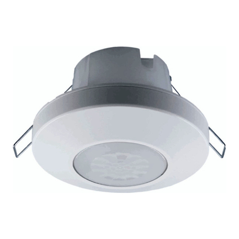
PIR Detector
9721WHW
DETA Electrical Company Limited
Kingsway House Laporte Way
Luton Bedfordshire LU4 8RJ UK
NPD 0519 April 2016 MCINS10 V1 Tel: +44 (0)1582 544 544 Technical Helpline: +44(0)1582 544 548
Connect
Features
Start Here
Deta Connect PIRs can be controlled by the Connect App by pairing it with
the Connect Link hub.
PIRs can be set & reset remotely –Home or Away, provided there’s a
Broadband connection
.
Go online
Because we are always making updates and improvements to Deta Connect
products, we need to ensure that you have the most up to date instruction
guide. Please visit the link below to view the current manual.
www.detaconnect.co.uk
Quick reference instructions
Please refer to the online instruction guide BEFORE attempting installation.
The diagram on the following page provides a useful reference when
installing and setting up the product. Deta Connect is fully legal to install in
your own home: however, if in doubt always consult a qualified electrician.
Set up and Installation
Setup
The PIR sensor will trigger any Deta Connect receiver, such as a Dimmer
Switch or a Power Socket, to which it is ‘Linked’. It is possible to link a PIR to
as many Deta Connect devices as desired as long as they are within its range
(approx. 10-15m indoors under normal conditions).
Linking the PIR to a Deta Connect device
1. Place the Deta Connect device that you wish to control in ‘Linking’ mode.
For information on how to do this please refer to the instruction manual for
that specific Deta Connect device.
2. Whilst the Deta Connect device is in linking mode, move the slider
marked ‘Learn’ on the rear of the PIR to its opposite position. The LED light
on the target device will flash to confirm that the PIR is linked. This process
can be repeated to control multiple devices from one PIR.
Setting The Detection Angle
Setting the detection angle will determine the area in which the presence of
movement will trigger the PIR. This angle can be altered by adding the lens
covers that partially cover the sensor lens.
Vertically, the maximum detection angle is always 65 degrees. Horizontally,
the maximum detection angle is 80 degrees without lens covers and
20 degrees with the lens covers.
The lens covers can be cut in order to alter the angle of detection. The
more that is cut away, the wider the detection angle.
PIR Detector
9721WHW
DETA Electrical Company Limited
Kingsway House Laporte Way
Luton Bedfordshire LU4 8RJ UK
NPD 0519 April 2016 MCINS10 V1 Tel: +44 (0)1582 544 544 Technical Helpline: +44(0)1582 544 548
Connect
Sending ‘on’ or ‘on & off’ commands
Once the PIR is linked, moving the ‘Learn’ slider to the position marked ‘1’
will turn on any linked devices when the PIR is triggered. Moving the slider
to the ‘1/0’ position will turn on linked devices, but also send an ‘off’
command after a customisable delay period (see next section).
Setting the ‘off’ command delay
If the Learn slider is set to ‘1/0’, then an ‘off’ command will be sent to a
linked Deta Connect device after the initial ‘on’ command sent by the PIR.
The period of time between these two commands can be customised
using the ‘Time delay’ slider. It has 4 positions: 5 sec/1 min/5 min/10 min.
The delay countdown will begin once movement is no longer detected after
the initial ‘on’ command has been sent.
Setting the light sensitivity
Setting the light sensitivity on the PIR sensor determines the light level at
which the PIR sensor will become active. The sensitivity can be set by
moving the position of the Lux slider marked ‘H/M/L’.
The slider has 3 positions: ‘H/M/L’.
• In position ‘H’ the PIR will be active at all light levels.
• In position ‘M’ the PIR will only become active at low daylight levels.
• In position ‘L’ the PIR will only become active in darkness (or very low
light).
NOTE: When adjusting the Lux setting it may take up to 30 seconds for the
PIR to acclimatise to the new light setting.
Finalising Setup
Once the PIR has been linked to its target Deta Connect
devices and the
settings adjusted, it can be mounted in its final position. Once in position, it
is important to allow at least 30 seconds for the PIR to acclimatise to the
light level in its new environment. Until this process has taken place, the unit
may not perform as expected.
Battery Low Indicator
The ‘Battery low’ indicator is positioned inside the sensor lens. If the battery
is low, the indicator will blink after the PIR has sent a command to inform
that the batteries need changing.
Important things to consider
Signal Range
•Reliable range of operation is approximately 15 metres indoors and up
to 100m outdoors using the Connect Link/WiFi-Link. This figure may
vary depending upon the environment; very thick walls, bodies of
water or large metal objects may interfere with radio range.
•If the distance between the transmitter and receiver is too great to
achieve reliable operation, the Connect Signal Booster may be used in
conjunction with this product to increase the range.
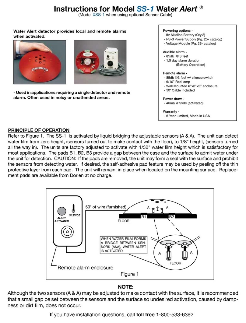
Voltage
2 x 1.5V
Battery Type
AAA
Radio Frequency
433.92MHz
Lux slider
Learn slider
Delay slider

Other Deta Security Sensor manuals

Deta EVOLO EVC7007 Mounting instructions

Deta

Deta EVOLO EVC7007 Mounting instructions

Deta SILENT 100 230V User manual

Deta

Deta SILENT 100 230V User manual

Popular Security Sensor manuals by other brands

EsiWelma Sensigas URS20SE manual

EsiWelma

EsiWelma Sensigas URS20SE manual

Regin HTRT5W instructions

Regin

Regin HTRT5W instructions

SILENTRON 5011 manual

SILENTRON

SILENTRON 5011 manual

Kidde KI-PHD Installation sheet

Kidde

Kidde KI-PHD Installation sheet

MSA Orion G operating manual

MSA

MSA Orion G operating manual

Honeywell 1031030 quick start guide

Honeywell

Honeywell 1031030 quick start guide

Mhouse MAD5 Instructions for installation

Mhouse

Mhouse MAD5 Instructions for installation

Distech Controls FS-WLDS Series Hardware installation guide

Distech Controls

Distech Controls FS-WLDS Series Hardware installation guide

LED Group ROBUS RLN7303W-25 quick start guide

LED Group

LED Group ROBUS RLN7303W-25 quick start guide

Vega VEGATRENN 149A EX operating instructions

Vega

Vega VEGATRENN 149A EX operating instructions

LST Orbis RB-10004 Specifications

LST

LST Orbis RB-10004 Specifications

System Sensor L-Series Installation and maintenance instructions

System Sensor

System Sensor L-Series Installation and maintenance instructions

iRay Technology Mars1417VS user manual

iRay Technology

iRay Technology Mars1417VS user manual

QMI MULTIPLEX Series manual

QMI

QMI MULTIPLEX Series manual

Steren VCA-500 instruction manual

Steren

Steren VCA-500 instruction manual

SEW-Eurodrive MOVIFIT FC manual

SEW-Eurodrive

SEW-Eurodrive MOVIFIT FC manual

Varex Imaging 2530C-G5 manual

Varex Imaging

Varex Imaging 2530C-G5 manual

sebaKMT Correlux C-3 user manual

sebaKMT

sebaKMT Correlux C-3 user manual

manuals.online logo
manuals.online logoBrands
  • About & Mission
  • Contact us
  • Privacy Policy
  • Terms and Conditions

Copyright 2025 Manuals.Online. All Rights Reserved.