manuals.online logo
Brands
  1. Home
  2. •
  3. Brands
  4. •
  5. CP
  6. •
  7. Security Sensor
  8. •
  9. CP EBR-MINPIR User manual

CP EBR-MINPIR User manual

Overview
The EBR-MINPIR-DALI presence detector provides
automatic control of lighting. It is connected to the Rapid
DALI Gateway via a DALI network.
Functioning as a presence detector, the unit can turn lights
on when a room is occupied and off when the room is
empty.
An adjustable internal light sensor provides light level
information to the Rapid system to allow lights to be kept
off if sufficient daylight is present, and to enable maintained
illuminance for dimming systems.
An integral IR sensor in the unit allows the unit to be
commissioned, and used in conjunction with a remote
control handset (part no: UHS) to:
 Act as a conventional dimmer
 Override the unit on or off
This detector is ideal for mounting in chill beams or
continuous run lighting.
DALI network miniature PIR with photocell
EBR-MINPIR-DALI
Product Guide
PIR Sensor
Detects movement within the unit’s detection range,
allowing load control in response to changes in occupancy.
IR Receiver
Receives control and programming commands from an
IR (infrared) handset.
Light Level Sensor
Measures the overall light level in the detection area
Status LEDs
The LED flashes Red to indicate the following:
Walk Test LED active when movement is detected
Valid setting received
Sensor head
PIR lens
which covers...
IR Receiver
Light Level Sensor
Status LED
Features
2
Rapid Area Controller
Rapid PIR
Rapid Scene plates
Standard light switches
3 core SELV DALI bus
Rapid Microwave
DALI light fitting with DALI
emergency inverter
EBR-MINPIR-DALI
Mini PIR integrated into lighting run
DALI light fitting
EBR-CPIR-DALI
CAT 5 cable CAT 5 cable
Rapid DALI gateway
System wiring example
Detection diagram
Walk towardsWalk across
Height Range Diameter
7m 10m
2.8m 5m
Height Range Diameter
7m 16m
2.8m 9m
Note: illustration shows an average of the walk across and walk towards figures below.
EBR-BB-IN-DALI
3
Installation
Mounting
DA
DA
DALI
Choosing a Suitable Location
The detector should be sited so that the occupants of the room fall inside the detection pattern shown on page 1, at a
recommended ceiling height of 2.8m. Note that the lower the sensor is installed the smaller the detection range will be,
subject to the parameters shown on the detection diagram.
 Avoid direct sunlight entering the sensor.
 Do not site within 1m of forced air heating or ventilation.
 Do not fix to a vibrating surface.
 Do not exceed maximum length of cable (200m) on data bus.
 Do not exceed maximum bus loading (200mA).
Wiring diagram
The EBR-MINPIR-DALI supplied with two 1m wires to
connect to the DALI network. The device is designed to
operate correctly with reversed polarity.
Remove bottom
of 2 small
retention arms
Standalone mounting
The product is designed to be mounted into a ceiling tile or plasterboard ceiling using the flush holder as shown below. If
flush mounting in a panel >6mm thick, remove bottom of retention arms with side cutters.
Luminaire mounting
The product is also designed to be mounted directly to a luminaire, either on the inside or outside.
 The PIR lens must have a view outside the luminaire.
 For optimum lux measurement, the lens must be shielded as much as possible from the light source.
 If flush mounting in a panel >6mm thick, remove bottom of retention arms with side cutters.
Flush mounting
The product can be mounted using the
flush mount ring as shown. If flush
mounting in a material that is greater
than 6mm thick, remove bottom of
retention arms with side cutters. A
32mm diameter hole will be required to
mount the flush mount ring.
Ø19.5m
Ø3.5m
19mm
Use the lugs on rear of detector to
secure into thin sheet metal (1mm
max.).
Surface mounting
Devices (detectors / input units) and ballast combinations
for 200mA supply.
This assumes that the sensor LEDs are all on, and the
sensor is receiving IR communication.
 4 devices and up to 64 ballasts
 5 devices and up to 55 ballasts
 6 devices and up to 44 ballasts
 7 devices and up to 33 ballasts
 8 devices and up to 22 ballasts
 9 devices and up to 12 ballasts
 10 devices and up to 2 ballasts
In most realistic scenarios, only one LED is on at a time
and only one detector is receiving IR; guidance changes
to.
 10 devices up to 64 ballasts
 11 devices up to 60 ballasts
 12 devices up to 55 ballasts
 13 devices up to 50 ballasts
 14 devices up to 48 ballasts
 15 devices up to 44 ballasts
Addressing limits of DG64
 5 input units of 7 channels each
 10 detectors
DALI bus loading
4
Due to our policy of continual product improvement CP Electronics reserves the right to alter the specification of this product without prior notice.
C.P. Electronics Ltd
Brent Crescent
London
NW10 7XR
United Kingdom
Tel: + 44 (0) 333 900 0671
Fax: + 44 (0) 333 900 0674
www.cpelectronics.co.uk
enquiry@cpelectronics.co.uk
Ref. #WD585 Issue 3
Dimensions See diagrams opposite
Weight 0.10kg
Supply Voltage 9.5VDC—22.5VDC via DALI
Current consumption 8mA
DALI bus Cannot be considered as SELV
since DALI, ballasts only offer
basic insulation, therefore all
devices on the DALI bus must be
wired as if carrying mains
potential.
Cable 1m cable 2 x 0.65mm2
Material (casing) Flame retardant ABS
Compliance EMC-2014/30/EU
LVD-2014/35/EU
Technical data
Part numbers
Part number Description
Sensor EBR-MINPIR-DALI DALI network ceiling PIR with photocell
Accessories UHS User handset override on/off; lux up/lux down
UHS3 User override remote handset on/off
UHS3 (2) User override remote handset, off only
UNLCDHS Universal LCD programming handset
Sensor head
Flush ring
25
19
31
1
Ø38
FM 45789 EMS 534520 OHS 642036

Other CP Security Sensor manuals

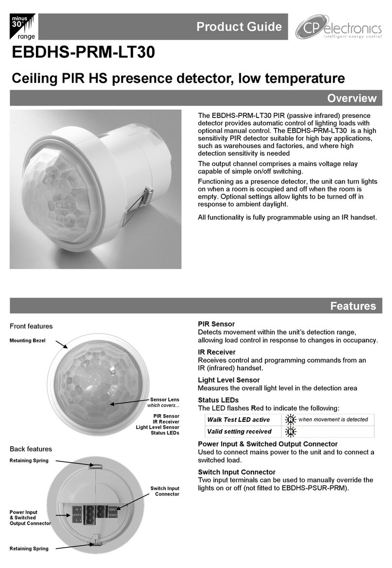
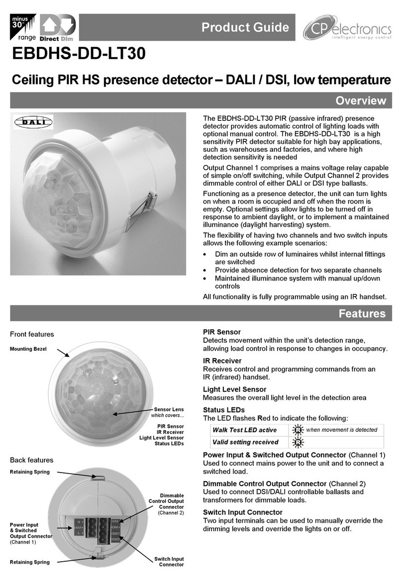
CP EBDHS-PRM-LT30 User manual

CP

CP EBDHS-PRM-LT30 User manual

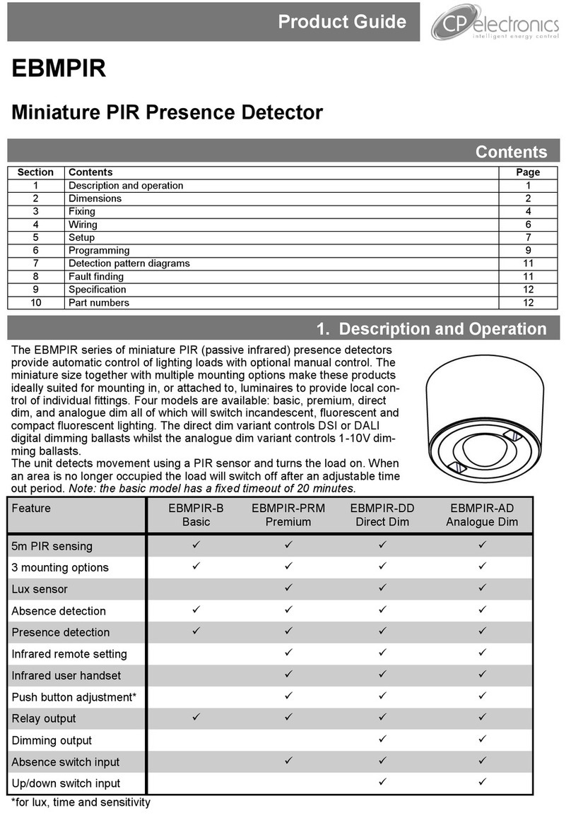
CP EBMPIR User manual

CP

CP EBMPIR User manual

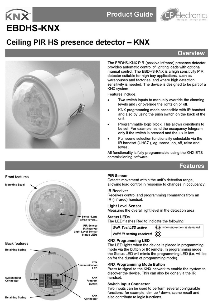
CP EBDHS-KNX User manual

CP

CP EBDHS-KNX User manual

CP EBDHS-DD-LT30 User manual

CP

CP EBDHS-DD-LT30 User manual

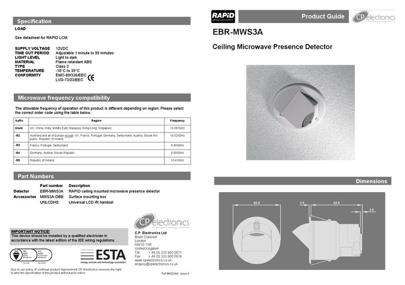
CP EBR-MWS3A User manual

CP

CP EBR-MWS3A User manual

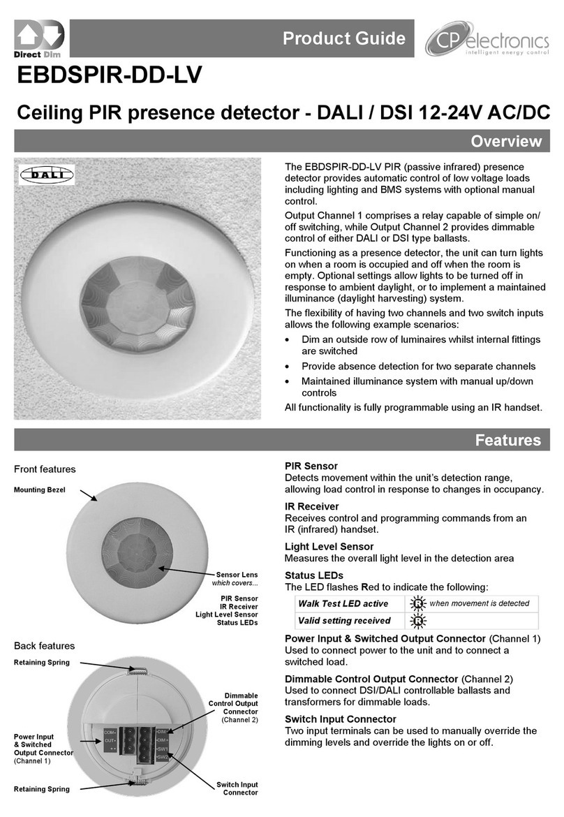
CP EBDSPIR-DD-LV User manual

CP

CP EBDSPIR-DD-LV User manual

Popular Security Sensor manuals by other brands

Interlogix DC105 Series Installation sheet

Interlogix

Interlogix DC105 Series Installation sheet

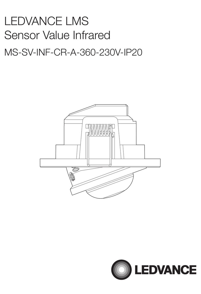
Ledvance MS-SV-INF-CR-A-360-230V-IP20 quick start guide

Ledvance

Ledvance MS-SV-INF-CR-A-360-230V-IP20 quick start guide

Orbis COMBIMAT 12M operating instructions

Orbis

Orbis COMBIMAT 12M operating instructions

TEM EM31 user manual

TEM

TEM EM31 user manual

LinMot DM01-23-FS installation guide

LinMot

LinMot DM01-23-FS installation guide

Hobo HOBOnet RXW EC-5H quick start guide

Hobo

Hobo HOBOnet RXW EC-5H quick start guide

UTC Fire and Security interlogix RF-DC101 Series Installation sheet

UTC Fire and Security

UTC Fire and Security interlogix RF-DC101 Series Installation sheet

Quest Engineering Q40 manual

Quest Engineering

Quest Engineering Q40 manual

Tecnoalarm MINIEXPLORER manual

Tecnoalarm

Tecnoalarm MINIEXPLORER manual

Eminent EM8650 manual

Eminent

Eminent EM8650 manual

Orno OR-AK-1202 Operating and installation instructions

Orno

Orno OR-AK-1202 Operating and installation instructions

Simpson SFI-16.1 installation manual

Simpson

Simpson SFI-16.1 installation manual

Ferno ULTRALITE X User instructions

Ferno

Ferno ULTRALITE X User instructions

Omron K8AC-H2 manual

Omron

Omron K8AC-H2 manual

Shinko SE2EA-1-0-0 instruction manual

Shinko

Shinko SE2EA-1-0-0 instruction manual

DMP Electronics 1122INT installation guide

DMP Electronics

DMP Electronics 1122INT installation guide

Pyronix KX10DTP quick start guide

Pyronix

Pyronix KX10DTP quick start guide

Inficon UL5000 Technical handbook

Inficon

Inficon UL5000 Technical handbook

manuals.online logo
manuals.online logoBrands
  • About & Mission
  • Contact us
  • Privacy Policy
  • Terms and Conditions

Copyright 2025 Manuals.Online. All Rights Reserved.