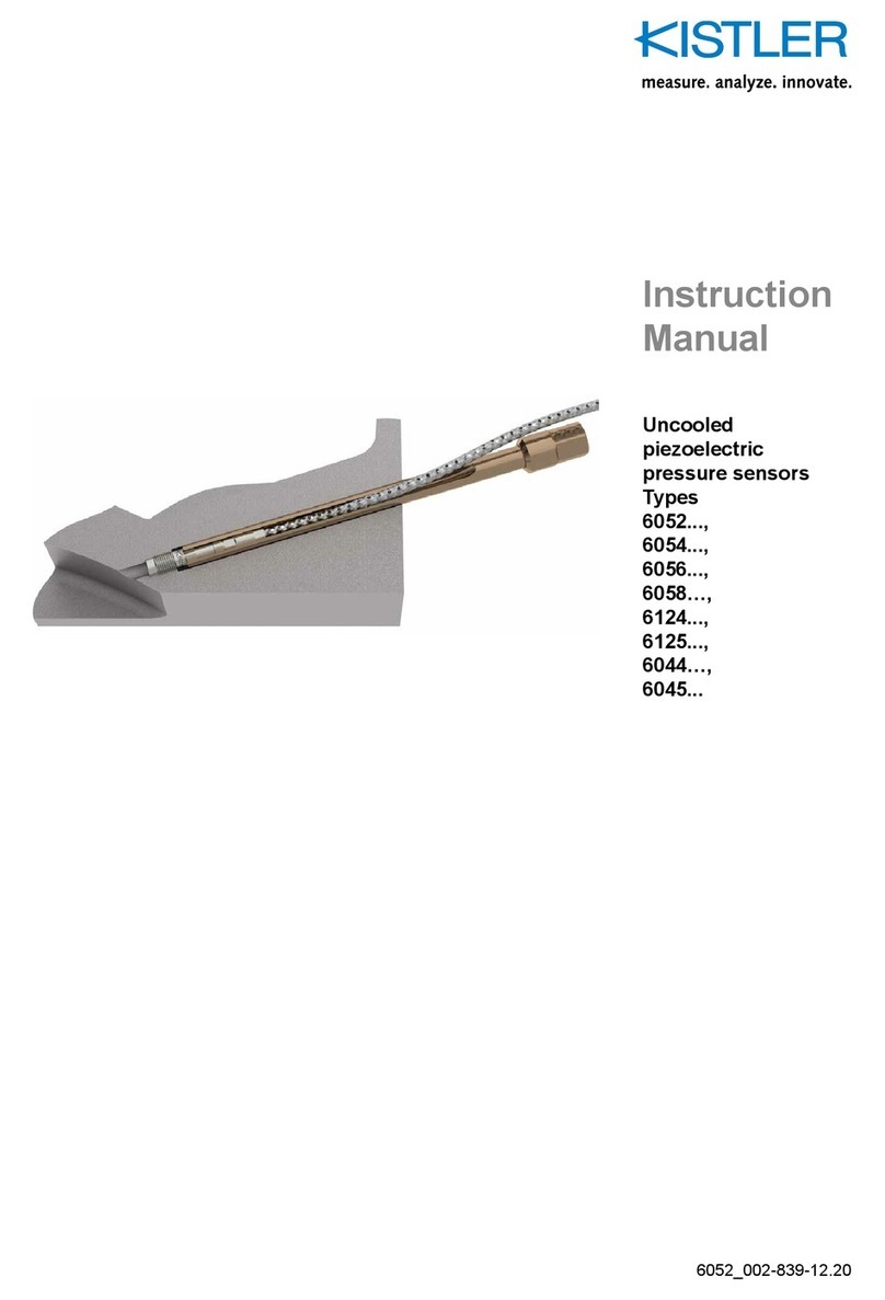
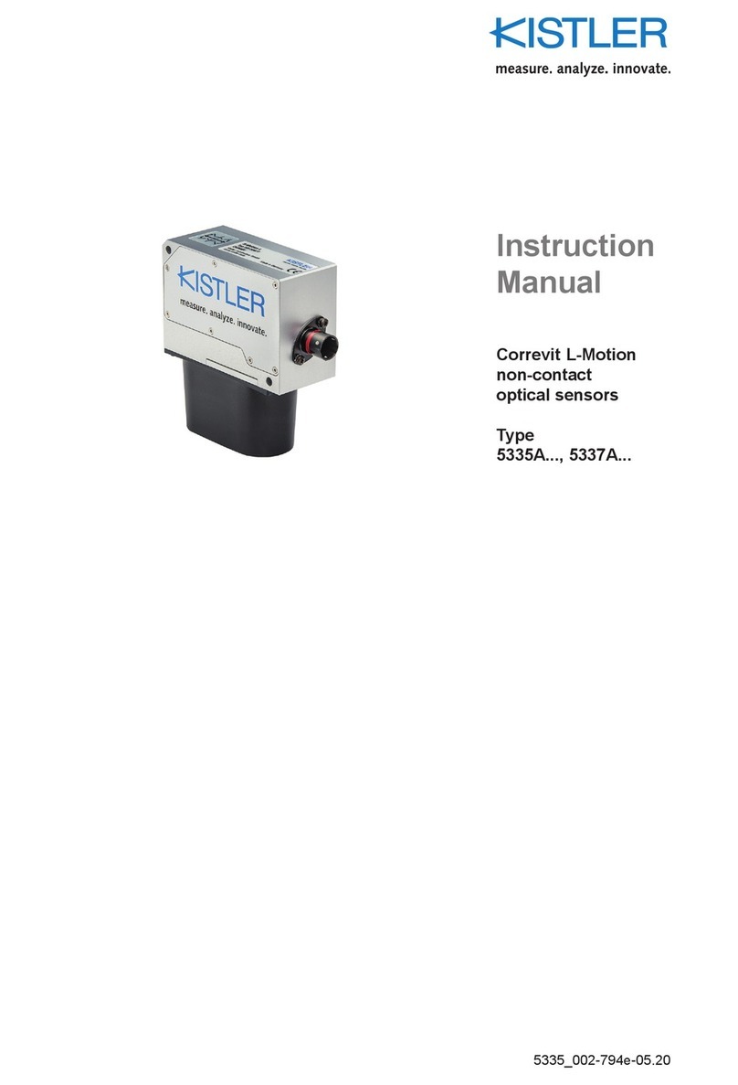
Kistler CHFA Series User manual

Instruction
Manual
HF Sensors
Optical Laser Height
Sensors
Type CHFA…
CHFA_002-583e-08.12

Instruction
Manual
HF Sensors
Optical Laser Height
Sensors
Type CHFA…
CHFA_002-583e-08.12


Foreword
CHFA_002-583e-08.12 Page 1
Foreword
Thank you for choos ng a K stler qual ty product
character zed by techn cal nnovat on, prec s on and long
l fe.
Informat on n th s document s subject to change w thout
not ce. K stler reserves the r ght to change or mprove ts
products and make changes n the content w thout
obl gat on to not fy any person or organ zat on of such
changes or mprovements.
©2011 … 2012 K stler Group. All r ghts reserved. Except as
expressly prov ded here n, no part of th s manual may be
reproduced for any purpose w thout the express pr or
wr tten consent of K stler Group.
K stler Group
Eulachstrasse 22
8408 W nterthur
Sw tzerland
Tel. +41 52 224 11 11
Fax +41 52 224 14 14
nfo@k stler.com
www.k stler.com
K stler Automot ve GmbH
Competence Center Wetzlar
Charlotte-Bamberg-Str. 12
35578 Wetzlar
Germany
Tel. +49 6441 9282 0
Fax +49 6441 9282 17
Info.kar@k stler.com

Content
Page 2 CHFA_002-583e-08.12
Content
1.
Introduction ...................................................................................................................................
2.
Important Notes ............................................................................................................................. 5
2.1
For Your Safety .................................................................................................................... 5
2.2
D sposal Instruct ons for Electr cal and Electron c Equ pment ................................................ 7
2.3
Software Upgrades and Updates .......................................................................................... 7
3.
Product Overview .......................................................................................................................... 8
3.1
General Descr pt on .............................................................................................................. 8
3.2
Features ............................................................................................................................... 9
3.3
Appl cat on ........................................................................................................................... 9
3.4
Accessor es ........................................................................................................................... 9
.
Technical Data ............................................................................................................................. 10
4.1
Spec f cat ons ...................................................................................................................... 10
4.2
P n Ass gnments ................................................................................................................. 11
4.3
Sensor Sett ngs ................................................................................................................... 13
4.3.1
Average T me ........................................................................................................ 13
4.3.2
Buffer T me ........................................................................................................... 13
5.
Setup and Connection .................................................................................................................. 1
5.1
Mount ng Opt ons ............................................................................................................. 14
5.2
Sensor Mount ng J g ........................................................................................................... 16
5.3
Mount ng Instruct ons ....................................................................................................... 17
5.3.1
Installat on w th Suct on Holder ............................................................................. 17
5.3.2
Installat on w th Magnet Holder ............................................................................ 25
5.3.3
Install ng the Safety L ne ........................................................................................ 29
5.4
Connect ng the Sensor ....................................................................................................... 31
5.4.1
Connect ng the Sensor to a Data Acqu s t on System ............................................. 31
5.4.2
Sensor Conf gurat on ............................................................................................. 31
6.
Sensor-specific Software Description ........................................................................................... 32
6.1
Project W ndow Sett ngs HF Sensors .................................................................................. 32
6.1.1
Measurement D splay ............................................................................................ 32
6.1.2
F lter ...................................................................................................................... 33
6.1.3
CAN-Bus ............................................................................................................... 34
6.2
CAN Protocol ..................................................................................................................... 35
6.2.1
Def n t ons of the Frame ........................................................................................ 36
6.3
Generat ng CAN Database f les (CanDB) ............................................................................ 37

Content
CHFA_002-583e-08.12 Page 3
7.
Troubleshooting ........................................................................................................................... 38
7.1
Cables and Power Supply .................................................................................................... 38
7.2
Protect on Glass .................................................................................................................. 38
7.3
Operat ng Range ................................................................................................................ 38
7.4
Software ............................................................................................................................. 38
7.5
CAN .................................................................................................................................... 39
7.6
Env ronmental Cond t ons ................................................................................................... 39
7.7
Serv ce ................................................................................................................................ 39
8.
Appendix ...................................................................................................................................... 0
Total pages: 40

Opt cal Laser He ght Sensors Type CHFA…
Page 4 CHFA_002-583e-08.12
1. Introduction
Please take the t me to thoroughly read th s nstruct on
manual. It w ll help you w th the nstallat on, ma ntenance,
and use of th s product.
To the extent perm tted by law K stler does not accept any
l ab l ty f th s nstruct on manual s not followed or
products other than those l sted under Accessor es are
used.
K stler offers a w de range of products for use n measur ng
technology:
P ezoelectr c sensors for measur ng force, torque, stra n,
pressure, accelerat on, shock, v brat on and acoust c-
em ss on
Stra n gage sensor systems for measur ng force and
torque
P ezores st ve pressure sensors and transm tters
S gnal cond t oners, nd cators and cal brators
Electron c control and mon tor ng systems as well as
software for spec f c measurement appl cat ons
Data transm ss on modules (telemetry)
K stler also develops and produces measur ng solut ons for
the appl cat on f elds eng nes, veh cles, manufactur ng,
plast cs and b omechan cs sectors.
Our product and appl cat on brochures w ll prov de you
w th an overv ew of our product range. Deta led data
sheets are ava lable for almost all products.
If you need add t onal help beyond what can be found
e ther on-l ne or n th s manual, please contact K stler's
extens ve support organ zat on.

Important Notes
CHFA_002-583e-08.12 Page 5
2. Important Notes
2.1 For Your Safety
Please read carefully before operat ng the equ pment.
K stler s not respons ble for damage that may occur when
th s system s used n any way other than that for wh ch t
s ntended.
To assure safe and proper operat on, all suppl ed
equ pment, components and/or accessor es must be
carefully transported and stored, as well as profess onally
nstalled and operated. Careful ma ntenance and usage n
full accordance w th operat ng nstruct ons s mperat ve.
The equ pment should be nstalled and operated only by
qual f ed persons who are fam l ar w th dev ces of th s type.
Local regulat ons may not perm t the operat on of motor
veh cles on publ c h ghways wh le the equ pment s
mounted on the exter or of the veh cle.
Laser rad at on s em tted from th s dev ce. Do not stare
nto beam!
Laser class 3R accord ng to DIN EN 60825-1:2001-11,
laser power: < 5 mW, wave length: 660 nm (red).

Opt cal Laser He ght Sensors Type CHFA…
Page 6 CHFA_002-583e-08.12
Do not use defect ve or damaged equ pment,
components and/or accessor es.
Do not mod fy or change the equ pment or ts
accessor es n any way.
Equ pment must be mounted f rmly and securely.
Improper use or mount ng of the equ pment may affect
the safety of the veh cle and/or occupants. The
equ pment must not be mounted and/or operated n
any way that may comprom se veh cle or and/or
occupant safety.
Do not mount equ pment, components and/or
accessor es near heat sources (e.g. exhaust).
The sensor and/or sensor components may be
damaged f power s appl ed for extended per ods,
espec ally n hot env ronmental cond t ons.
To avo d damage to the sensor lens, please do only
clean t w th a m cro-f ber cloth.
Use only or g nal equ pment, components and/or
accessor es ncluded n the scope of del very.
Always note correct p n ass gnments and operat ng
voltages when connect ng equ pment to power
suppl es, data acqu s t on/evaluat on systems, and/or
any other appl cable system or component. Equ pment
may be damaged f not properly connected and/or
operated.
We recommend us ng only cables suppl ed w th n the
scope of del very. If t s necessary to make cables,
always note correct p n.
K stler assumes no l ab l ty for damages caused due to
the use of cables other than del vered by K stler.
D sconnect power from the sensor f the veh cle s
stat onary for extended per ods.
For add t onal nformat on, please call the K stler
Hotl ne +49 6441 9282 82 or send an E-Ma l to
hotl ne.kcd@k stler.com.

Important Notes
CHFA_002-583e-08.12 Page 7
2.2 Disposal Instructions for Electrical and Electronic Equipment
Do not d scard old electron c nstruments n mun c pal
trash. For d sposal at end of l fe, please return th s
product to an author zed local electron c waste d sposal
serv ce or contact the nearest K stler Instrument sales
off ce for return nstruct ons.
2.3 Software Upgrades and Updates
K stler may from t me to t me supply upgrades or updates
for embedded software. Such upgrades or updates must
always be nstalled.
K stler decl nes any l ab l ty whatsoever for any d rect or
consequent al damage caused by products runn ng on
embedded software wh ch has not been upgraded or
updated w th the latest software suppl ed.

Opt cal Laser He ght Sensors Type CHFA…
Page 8 CHFA_002-583e-08.12
3. Product Overview
3.1 General Description
HF laser he ght-sensors are des gned for non-contact
d stance measurement for veh cle dynam cs test ng.
Laser he ght-sensors of the HF ser es use the pr nc ple of
opt cal tr angulat on. A v s ble red laser s focused onto the
road surface. Reflected l ght s coll mated onto a l near
CCD array. The d stance to the object s calculated from
the pos t on of the l ght spot on the CCD array. The output
of the sensor s d rectly proport onal to the measured
he ght.
HF sensors can be mounted together w th a Correv t
®
SFII-P at the same holder, thus enabl ng s multaneous
measurement of s desl p angle and veh cle r de he ght
relat ve to spr ng travel.
HF sensors are conf gured w th the CeCalW n Pro Software
v a the ser al port (RS-232C).
F g. 1: HF sensor, mounted w th magnet holder at the
rear passenger door

Product Overv ew
CHFA_002-583e-08.12 Page 9
3.2 Features
Work ng ranges of 100 ... 900 mm, depend ng on type:
HF-250C: 100 ... 350 mm, HF-500C: 125 ... 625 mm,
HF-750C: 150 ... 900 mm
For stat c and dynam c measurements
Compact des gn
W th spray guard for better performance on wet
surfaces
S gnal outputs: Analog, CAN and RS-232C
Negl g ble serv ce and ma ntenance requ rements
3.3 Application
He ght-sensors for measur ng e.g. p tch and roll angle
accord ng to ISO 4138 (steady-state c rcular-course dr ve).
Further f elds of appl cat on are for nstance upl ft
measurements, spr ng deflect on, dynam c t re flat spott ng,
t re l ft-off (F shhook Test).
Two HF sensors mounted at the wheel enable dynam c
camber angle measurement (refer to the K stler DCA
System).
3. Accessories
Included Accessories Type/Art. No.
S gnal cable HF 1xBNC, 2xbunch, l = 1 m KCD14992
S gnal cable HF 6 p n. Lemo, l = 1 m KCD14993
Connect on cable CAN, l = 1 m KCD15622
Connect on cable RS-232C, l = 1 m KCD14991
USB Adapter KCD13971
M n fold ng rule KCD14643
Mult med a-CD ncl. software & manuals KCD11343
Sensor cal brat on HF sensors KCD17166
Screw dr ver Torx T10 KCD15887
Hexagon wrench 6 kt 4 mm KCD14283
Screw set for HF KCD17195
Transport case, complete KCD17196
Optional Accessories Type/Art. No.
4-po nt magnet c holder KCD15694
8-po nt magnet c holder KCD14091
3-po nt suct on holder KCD16049
Wheel mount ng system KCD14178

Opt cal Laser He ght Sensors Type CHFA…
Page 10 CHFA_002-583e-08.12
. Technical Data
.1 Specifications
Performance Specifications
HF-250C HF-500C HF-750C
Measurement range mm 100 ... 350 125 ... 625 150 ... 900
Resolut on mm 0,1 0,2 0,3
L near ty % ±0,2 ±0,2 ±0,3
Sampl ng rate1) kHz 0,3 … 8
L ght source Laser
Laser class 3R (IEC608251)
Laser power mW <5
Wave length nm 660
Spot s ze (approx.) mm 1x2
Signal Outputs
Analog output V 0 … 10
Interfaces
CAN (Intel) 2) 2.0B
RS-232C yes
System Specifications
Power supply V
10… 18
Power consumpt on at 12 V W 1,5
Temperature range
Operat on °C –5 … 60
Storage °C –10 … 70
Rel. Hum d ty (non-condens ng) % 5 … 80
Protect on standard (cable mounted) IP67
D mens ons
(LxWxH, w thout spray guard)
mm 100x20x40
We ght (w thout cable) grams 155
Case alum num, anod zed
1) a sampl ng rate up to 8 kHz s poss ble on surfaces w th h gh reflect on
2) output rate CAN max. 250 Hz

Techn cal Data
CHFA_002-583e-08.12 Page 11
.2 Pin Assignments
Sensor connector, analog/digital, 9 pin MIL, male
Pin
1
2
3
4
5
6
7
8
9
Signal
TXT
RXD
CAN+
CAN–
Sh eld
GND
S gnal
9 … 18 V
0 V
Signal cable, 1 m 8 pin Binder with cable to 6 pin Lemo
Pin
1
2
3
4
5
6
Signal
n.c.
12 V
GND
n.c.
S gnal
0 V
Signal cable, 1 m 8 pin Binder with cable to BNC and
2x mm bunch pin plug
Bunch p n plug black 0 V
Bunch p n plug red 12 V
Pin
BNC S g.
BNC Sh eld
Signal
S gnal
GND

Opt cal Laser He ght Sensors Type CHFA…
Page 12 CHFA_002-583e-08.12
RS-232C output cable, 1 m 8 pin Binder with cable to
9 pin D-Sub and 2x mm bunch pin plug
Bunch p n plug black 0 V
Bunch p n plug red 12 V
Pin
1
2
3
4
5
6
7
8
9
Signal
10 k w th p n 7
TXD
RXD
n.c.
GND
n.c.
10 k w th p n 1
n.c.
n.c.
Output cable, 1 m 8 pin Binder with cable to 9 pin D-Sub
and 2x mm bunch pin plug
Bunch p n plug black 0 V
Bunch p n plug red 12 V
Pin
1
2
3
4
5
6
7
8
9
Signal
n.c.
CAN–
n.c.
n.c.
n.c.
n.c.
CAN+
n.c.
n.c.

Techn cal Data
CHFA_002-583e-08.12 Page 13
.3 Sensor Settings
The follow ng parameters can be set w th the help of
CeCalW n Pro.
.3.1 Average Time
Due to the h gh sampl ng rate and the small measur ng
spot, the sensor s gnal may be qu te rough on uneven
surfaces but t s poss ble to smoothen the s gnal by us ng a
mov ng average f lter. Source data are stored n a c rcular
buffer, and a new mean value s calculated each t me the
new result arr ves; therefore, the output may be regarded
as a mov ng average.
Please note that s gnal deta l and dynam cs w ll
decrease as the s gnal becomes ncreas ngly smooth.
Th s parameter spec f es the number of source results to
be averaged for der v ng the output value!
.3.2 Buffer Time
If the sensor s out of range or the laser spot s shaded, the
sensor output w ll show a zero value. To prevent these
erroneous measurements a buffer t me can be set.
If the sensor cannot acqu re a val d measurement value,
the sensor w ll put out the last val d value for th s t me
max mum. As soon as a new val d value s acqu red, the
sensor w ll put th s out.

Opt cal Laser He ght Sensors Type CHFA…
Page 14 CHFA_002-583e-08.12
5. Setup and Connection
5.1 Mounting Options
F g. 2: Poss ble mount ng pos t ons
In wet or snowy cond t ons, please mount the sensor at
the front of the veh cle. Th s w ll help to prevent
measurement anomal es that can be caused by spray
and/or blow ng snow.
1) Two HF sensors mounted at the wheel enable dynam c camber angle
measurement (refer to the DCA System).
DCA System
1)

Setup and Connect on
CHFA_002-583e-08.12 Page 15
To ach eve opt mum performance and accuracy, the
mount ng d stance from the lower surface of the sensor
body (not nclud ng the spray guard) to the road surface
must be w th n the spec f ed range (see chapter 4.1
Spec f cat ons).
F g. 3: Mount ng d stances
sensor body
road surface
HF
-
250C: 100 … 350 mm
HF-500C: 125 … 625 mm
HF-750C: 150 … 900 mm

Opt cal Laser He ght Sensors Type CHFA…
Page 16 CHFA_002-583e-08.12
5.2 Sensor Mounting Jig
F g. 4: Sensor d mens ons
The electron c un t s equ pped w th reverse polar ty
protect on. In the event that polar ty s nverted, the
un t w ll not be damaged. Immed ately d sconnect
power from the un t and correct the power supply
connect on.
M
ounting surface
Please keep free from st ckers or
labels!

Setup and Connect on
CHFA_002-583e-08.12 Page 17
5.3 Mounting Instructions
5.3.1 Installation with Suction Holder
F g. 5: 3-po nt suct on holder HF, Art. No. KCD15408
To assure proper funct on of the suct on holders, the
mount ng area must be free of grease, o l, dust and
other contam nants. For th s reason t s necessary to
clean the pa nted surface n the mount ng area before
attach ng the suct on holders. Do not use clean ng
products that leave res due of any k nd on the surface.
Always nspect the suct on mount ng un t before use.
Spec al attent on should be pa d to the cond t on of the
rubber suct on pads, wh ch must be absolutely ntact.
Replace damaged pads mmed ately.
Lock ng lever
Lock ng lever
Lock ng lever
Sensor mount ng plate
Suct on holder
Suct on holder
Pump ng p ston
Level nd cator
Top: Stab l zer element
Bottom: Suct on holder un t
This manual suits for next models
3
Table of contents
Other Kistler Security Sensor manuals
Popular Security Sensor manuals by other brands

PCB Piezotronics
PCB Piezotronics 118B11 Installation and operating manual

Radiodetection
Radiodetection RD8000 Quick Locating Guide

Honeywell Home
Honeywell Home PROSiXSMOKEV installation instructions

Inficon
Inficon TEK-Mate operating manual

LEYBOLD
LEYBOLD Ultratest UL 100 Plus operating instructions

FM Electronics
FM Electronics 4190-GB quick start guide