Kistler 9001C Series User manual

Instruction
Manual
9001C_002-928e-12.20
Piezoelectric Force Sensors,
Ring Force Transducers
Types 9001C ... 9091C,
9101C ... 9107C,
9130C ... 9137C

Page 1
9001C_002-928e-12.20
Thank you for choosing a Kistler quality product charac-
terized by technical innovation, precision and long life.
Information in this document is subject to change without
notice. Kistler reserves the right to change or improve its
products and make changes in the content without
obligation to notify any person or organization of such
changes or improvements.
© 2020 Kistler Group. Kistler Group products are protected
by various intellectual property rights. For more details visit
www.kistler.com. The Kistler Group includes Kistler Hol-
ding AG and all its subsidiaries in Europe, Asia, the Ameri-
cas and Australia.
Kistler Group
Eulachstrasse 22
8408 Winterthur
Switzerland
Tel. +41 52 224 11 11
info@kistler.com
www.kistler.com
Foreword
Foreword

Piezoelectric Force Sensors, Ring Force Transducers
9001C_002-928e-12.20Page 2 Page 39001C_002-928e-12.20
Content
1. Introduction .................................................................................................................................4
2. Important instructions................................................................................................................5
2.1 For your safety....................................................................................................................5
2.2 Disposal instructions for electrical and electronic equipment .............................................6
2.3 Unpacking...........................................................................................................................6
2.4 Notes on handling the sensor.............................................................................................6
2.5 Tips on use of manual ........................................................................................................7
3. General.........................................................................................................................................8
3.1 Applications ........................................................................................................................8
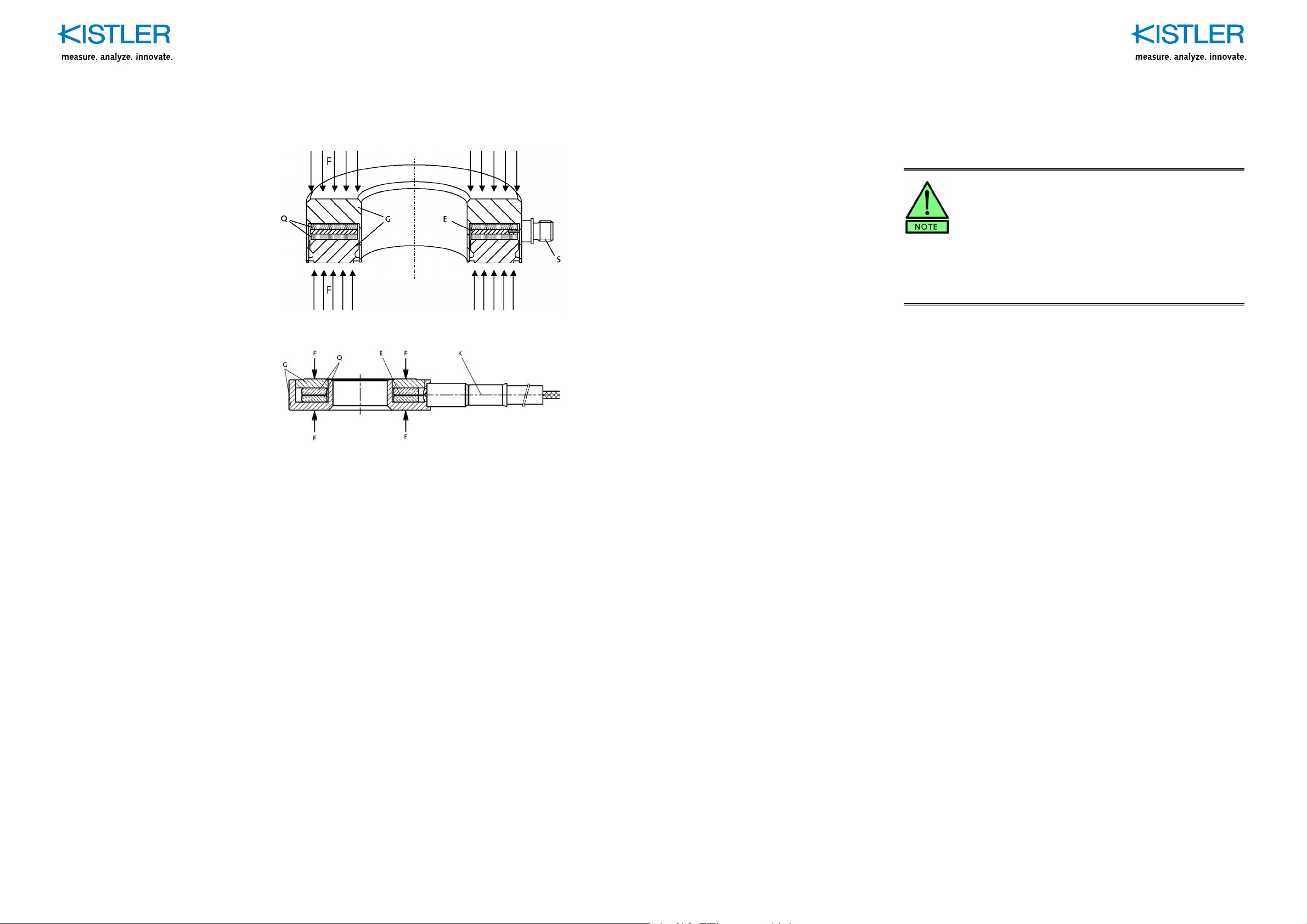
3.2 Sensor design and principle of operation ...........................................................................9
4. Mounting....................................................................................................................................11
4.1 General aspects of mounting ...........................................................................................11
4.1.1 Pretension and preload .......................................................................................11
4.1.2 Sensor in direct path of force ..............................................................................13
4.1.3 Sensor in force shunt .........................................................................................13
4.2 Structural design and force contact ..................................................................................14
4.2.1 Examples.............................................................................................................14
4.3 Effect of elasticity conditions on the measurements.........................................................17
4.3.1 Calculations related to engagement of force.......................................................18
4.3.2 Examples.............................................................................................................21
4.4 Mounting example ............................................................................................................24
4.5 Installation of sensor family 90x1C and 910xC ................................................................25
4.5.1 Type 9422A: mounting for compression forces only ...........................................25
4.5.2 Type 9420A: Mounting for both compression and tensile forces.........................27
4.6 Installation of big force sensors Type 9081C and 9091C .................................................29
4.7 Installation of a Slimline Sensor Types 9130C … 9137C .................................................30
4.7.1 Direct force path mounting ..................................................................................30
4.7.2 Type 9410A: mounting in force shunt mode........................................................31
5. Measurement.............................................................................................................................33
5.1 Basic arrangement of a measuring system ......................................................................33
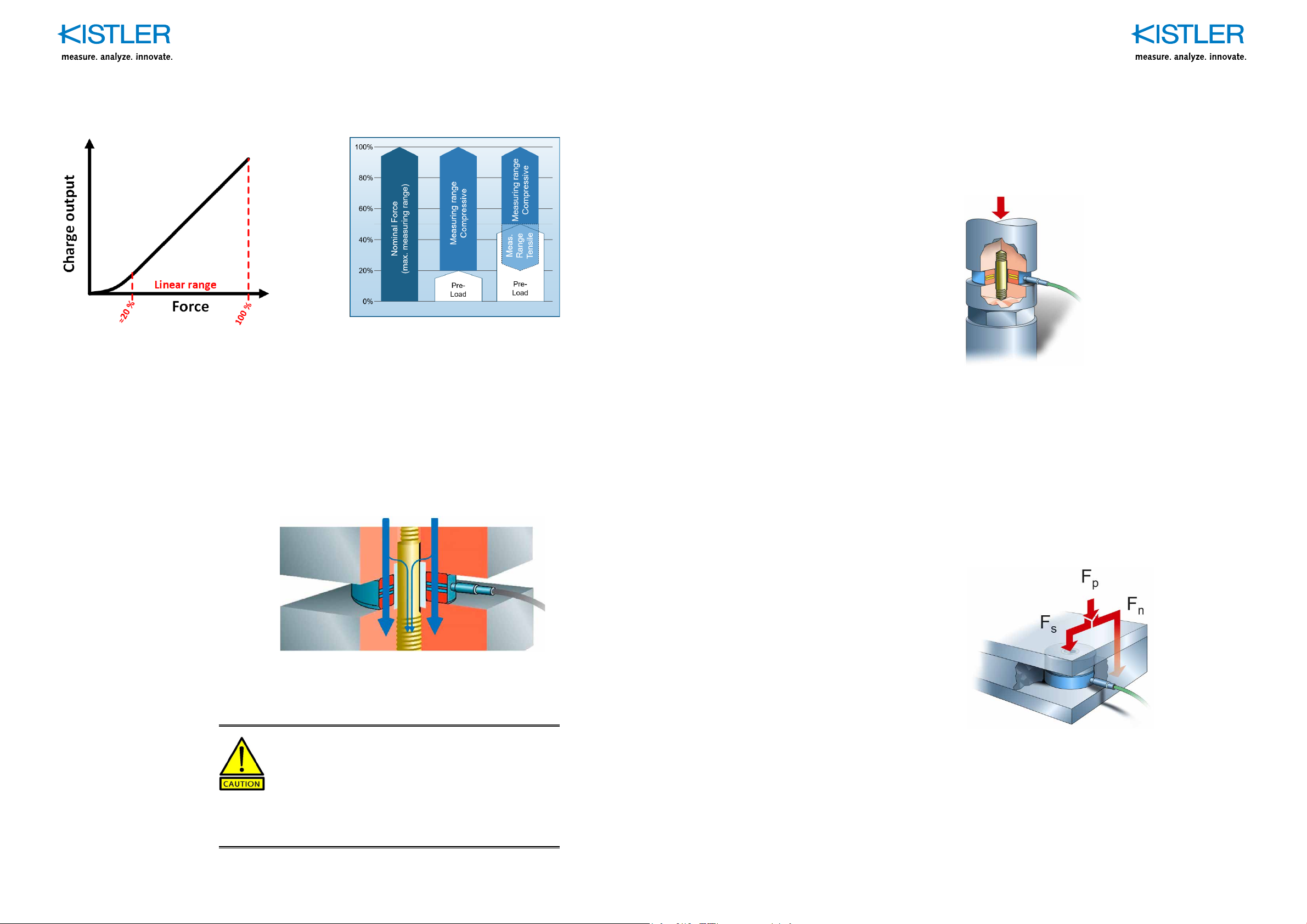
5.2 Range selection and threshold .........................................................................................34
5.3 Measuring high-frequency phenomena ............................................................................35
5.4 Measuring quasistatic phenomena...................................................................................35
5.5 Instructions and safety precautions ..................................................................................36
Total pages 55
6. Calibration and maintenance...................................................................................................37
6.1 In-Situ calibration of force sensors ...................................................................................37
6.1.1 Working point calibration by peak value comparison ..........................................37
6.1.1.1 Test system requirements....................................................................38
6.1.1.2 Reference sensor installation ..............................................................38
6.1.1.3 Load application...................................................................................39
6.1.1.4 Calibration process worksheet.............................................................40
6.1.2 Kistler calibration service.....................................................................................43
7. Troubleshooting........................................................................................................................44
7.1 Diagnosisandrecticationoffaults ..................................................................................44
7.2 Repairing Load Washer ....................................................................................................45
8. Technical data ...........................................................................................................................46
8.1 Optional accessories ........................................................................................................46
9. Appendix....................................................................................................................................47
9.1 Glossary ...........................................................................................................................47
9.2 Measurement uncertainty .................................................................................................50
9.3 Linearity ............................................................................................................................51
9.4 Frequency range ..............................................................................................................53
9.5 Inuenceoftemperature...................................................................................................54

Piezoelectric Force Sensors, Ring Force Transducers Important instructions
9001C_002-928e-12.20Page 4 Page 59001C_002-928e-12.20
1. Introduction
Thank you for choosing a quality product from Kistler.
Please read through this manual thoroughly to enable you
to fully exploit the various features of your product.
To the extent permitted by law Kistler accepts no liability
if this instruction manual is not followed or products other
than those listed under Accessories are used.
Kistler offers a wide range of measurement products
through to turnkey solutions:
Piezoelectric sensors for measuring pressure, force,
torque, strain, acceleration, shock and vibration
Strain gage sensor systems for measuring force and
torque
Piezoelectric pressure sensors and transmitters with
matchingmeasuringampliers
Matching measuring ampliers (charge ampliers, pi-
ezoresistive ampliers, etc.), displays and charge ca-
librators
Electronic control, monitoring and evaluation units as
wellassoftwareforspecicmeasurementapplications
Datatransmissionmodules(telemetry)
Kistler also develops and produces measuring solutions
fortheapplicationeldsengines,vehicles,manufacturing,
plastics and biomechanics sectors.
Our product and application brochures will provide you
with an overview of our product range. Detailed data
sheets are available for almost all products.
If you need additional help beyond what can be found
either on-line or in this manual, please contact Kistler‘s
extensive support organization.
2. Important instructions
It is absolutely essential to follow the instructions below,
which are intended to ensure your safety when working
with the equipment and guarantee a long, trouble-free
service life.
2.1 For your safety
Kistler force sensors have been thoroughly tested and
left the factory in perfectly safe condition. To maintain
this condition and ensure safe operation the user must
follow the instructions and warnings in this manual
Piezoelectric force sensors may only be mounted, used
and maintained by persons familiar with the equipment
andsuitablyqualiedfortheirparticularwork
If it has to be assumed that safe operation is no longer
possible, switch the equipment off and ensure it cannot
be switched on again inadvertently
It must be assumed that safe operation is no longer
possible when the product
shows visible signs of damage,
has been overloaded
is no longer operating,
has been in lengthy storage under unsuitable
conditions
has been subjected to rough transport conditions.
Mount the ring force transducer as specified. See section 4
„Mounting“ for details.
Secure all of the parts mounted on the force sensors
against the anticipated forces.

Piezoelectric Force Sensors, Ring Force Transducers Important instructions
9001C_002-928e-12.20Page 6 Page 79001C_002-928e-12.20
2.2 Disposal instructions for electrical and electronic equipment
Do not discard old electronic equipment in municipal trash.
For disposal at end of life, please return this product to
the nearest authorized electronic waste disposal service or
contact your Kistler sales office for instructions.
2.3 Unpacking
Check all of the packaging for any damage in transit,
which must be reported to the freight forwarder and the
responsible Kistler distributor.
Please check also for the completeness of the delivery
and report any missing parts to the responsible Kistler dis-
tributor.
2.4 Notes on handling the sensor
The specied environmental and operating require-
ments must be met when working with the sensor
The insulation resistance of piezoelectric sensors is of
criticalimportance;itmustmeetthevaluespeciedin
thedatasheet(upto1014 W).Toachievethisvalueall
plug connections must be kept scrupulously clean and
dry. The insulation resistance can be measured with
the corresponding insulation tester from Kistler
Protect all connector or cable parts between sensor
andchargeamplieragainstanydirt,andinparticular
make absolutely sure you never touch the front of any
connectorwithyourngers.Puttheincludedcoveron
if a connection is not being used
The cable for connecting the sensor to a charge amp-
lierisahigh-insulationtype.Ifnotincluded,useonly
suitable connecting cables or accesories specied by
Kistler
2.5 Tips on use of manual
We recommend that you read through the entire manual
thoroughly. However, if you cannot spare the time and are
already familiar with piezoelectric force sensors of Kistler,
you may skip to the sections with the information currently
required.
We have tried to organize this manual clearly so that the
required information is easily accessible.
Keep this manual in a safe place where it is readily acces-
si-ble at all times.
If you lose your manual please contact your Kistler distri-
butor for prompt replacement.

Piezoelectric Force Sensors, Ring Force Transducers General
9001C_002-928e-12.20Page 8 Page 99001C_002-928e-12.20
3. General
Piezoelectric force sensors are quartz crystal ring force
transducers. The force to be measured is transferred to
the quartz sensor elements via the cover plate and base
plate of the tightly welded steel housing. The quartz ele-
ments produce an electric charge proportional to the me-
chanical load. A charge amplier generates an electric
voltage from this charge. These signals are displayed, re-
corded or processed in the familiar way.
Thanks to the extremely high resolution of quartz it is pos-
sible to measure a change in force of the order of 1 N
under a pretension of several tons.
Theshape(loadwasher)andtherelativelysmalldimen-
sionsallowexibleapplicationandeasymounting.Stan-
dard accessories for special applications or mounting
conditions are available on the datasheets of the corres-
ponding sensor.
Sensitivity(chargeperunitforce)isaconstantofquartz
as a material. The associated threshold is virtually the
same for all the load washers of different sizes.
This has three unique advantages:
High level of overload protection, very small forces can be
measured with one sensor with a large measuring range
High rigidity; a sensor with a larger measuring range un-
dergoes less deformation
Several sensors can be electrically connected in parallel
toasinglechargeamplier.Theoutputsignalisthenthe
sum of all of acting forces
3.1 Applications
Kistler ring force transducers are very rigid and ideal for
measuring dynamic forces. This very high rigidity has ex-
tremely little effect on the dynamic characteristics of the
object being measured, in which they are mounted.
Depending on the size of the force, quasistatic measu-
re-ment can be performed over several minutes or even
hours(thesignaldriftisonlyabout±50mN/s).However,
truly static measurements over any length of time are not
possible.
On the other hand, after a pause of any length a sensor
undercontinuous static load(forexample, mounted ina
threadedconnection)canbereconnectedtoachargeam-
plierandthechangesinloadthenmeasuredaccurately.
Measurements of dynamic forces (AC mode) are also
possible over any length of time. Kistler load washers
have a virtually unlimited life and are not subject to sensi-
tivity drift caused by aging.
The force to be measured is transferred to the quartz sen-
sor elements via the cover plate and base plate of the
tightly welded steel housing. The quartz elements produce
an electrical charge proportional to the mechanical load.
Thesensitivity(chargeperunitforce,aconstantofquartz
as a material) and hence the threshold is virtually the
same for all of the different sized load washers.
3.2 Sensor design and principle of operation
A piezoelectric ring force transducer consists of one or
two crystal ring washers, an electrode and a housing with
connector(seeFig.1).
The force to be measured must be evenly distributed over
the ring surface. The mechanical compressive stress re-
sults in an electric charge being generated in the quartz
crystal. This charge is proportional to the applied force
and does not depend on the dimensions of the quartz
washers(longitudinalpiezoelectriceffect).

Piezoelectric Force Sensors, Ring Force Transducers Mounting
9001C_002-928e-12.20Page 10 Page 119001C_002-928e-12.20
a)
b)
S
Q = Quartz washers
E = Electrode
G = Housing
S = Connector
F = Force acting on the load washer
Fig. 1: Schematic section through a standard piezo-
electricringforcetransducera)andaSlimline
forcesensorb)
The generated charge is conducted from the electrode
and supplied to the plug connection. The polarity is cho-
sen so that a compression force generates a negative
charge, which is then converted into a positive voltage in
thechargeamplier.Thehousingservesasgroundcon-
nection. Unloading of the load washer produces a positive
charge.
Connecting several force sensors in parallel adds the
chargesoftheindividualsensorandthechargeamplier
measures the total force.
To ensure the forces to be measured are distributed even-
ly over the ring surfaces, the contact surfaces on the ob-
jectbeingmeasuredmustbeasat,rigidandnelyma-
chined as possible.
4. Mounting
If something is not clear or difculties are encoun-
tered when mounting piezo ring force transducers,
please contact the responsible Kistler distributor or,
if appropriate, the manufacturer, for advice. To enable
the query to be handled effectively it is important
to describe the measurement problem and provide
drawings or sketches that make the type of load,
engagement and point of application of the force
evident.
4.1 General aspects of mounting
Kistlerloadwashersmustbemountedbetweentwonely
machined(preferablyground),rigid,parallelsurfaces.This
allows force measurement over a wide frequency range.
TherecommendedsurfaceroughnessisRa=1,6μm.
4.1.1 Pretension and preload
Why to apply a pretension or preload:
Between the always imperfect surfaces inside and out-
side the sensor there are microgaps that act as inter-
posed spring elements. Preloading closes these gaps
to ensure force measurement is in the linear range and
freefromdisturbinginuences.(s.Fig.2)
Pretension eventually allows the measurement of both
compressionandtensionforces(s.Fig.3)
An optimal choice of preload allows to operate the sen-
sor in the range, where it is most robust against ben-
ding moments, which is at 50% of the nominal force of
thesensor.(4.3.1Calculationsrelatedtoengagement
offorce)
Pretension presses the contact surfaces together so
that the high rigidity of the sensor can be fully exploited

Piezoelectric Force Sensors, Ring Force Transducers Mounting
9001C_002-928e-12.20Page 12 Page 139001C_002-928e-12.20
Fig. 2: Linearity of force sensors Fig. 3: Measuring ranges depending on preload
Difference of pretension and preload:
The terms preload and preload force are often used as
synonyms, although they have a crucial difference: A
force is applied to the sensor by both preload and preten-
sion to overcome the nonlinear range of the sensor. How-
ever, when pretensioning a ring force transducer, a screw
is used through the center hole, resulting in a small force
shunt, which is not present with a pure preload. This force
shuntreduces the sensitivityofthe sensorby ≈5…10%,
depending on the layout.
Fig. 4: Pretension and the resulting force shunt through
bolt
How to preload:
When pretensioning, the force must be measured with the
sensoritself,andthechargeampliersettothesensitivity
speciedin thetechnicaldata.Asthepretensioningbolt
forms a force shunt, after being mounted the sensor
must be recalibrated to determine the sensitivity of the
complete measurement setup.
Calibratedsensorscomewithaspecicsensitivityvalue
for preloading.
4.1.2 Sensor in direct path of force
With direct force measurement almost the entire process
force passes through the sensor.
Fig. 5: Measurement in direct path of force
The total force applied (preload force Fv and process
forceFz)shallnotexceedthenominalforceofaringforce
transducer. Otherwise a bigger sensor has to be chosen.
In general, the force shunt effect of the preloading bolt is
neglectedwhenasensorsizehastobedened.Butifcir-
cumstances require it, the effective load on the quartz by
theprocessforceFzcanbereducedbythese≈5…10%
that are absorbed by the bolt. Check the datasheet of the
bolt accordingly.
4.1.3 Sensor in force shunt
Fig. 6: Example of indirect force measurement
If very large forces are to be measured or the sensor
cannot be positioned directly in the path of the force, it is
often mounted in a force shunt. This arrangement allows
the sensor to be used to solve a wide variety of measure-
ment problems. Due to it’s small dimensions, the Slimline
series 913x is very well suited for this purpose.

Piezoelectric Force Sensors, Ring Force Transducers Mounting
9001C_002-928e-12.20Page 14 Page 159001C_002-928e-12.20
4.2 Structural design and force contact
The full measuring range can only be exploited if the
force is evenly distributed. The mounting surfaces
should preferably be ground. Accessories like spherical
washers, force distributing rings, insulating washer and
force distributing caps make mounting easier in many
cases(seewww.kistler.com/force).Atthemaximumallo-
wed load of the particular load washer of whatever size a
surface pressure Gmaxofapproximately150N/mm2ari-
ses.
4.2.1 Examples
The ideal mode of force engagement produces an even
surface pressure on the ring force transducer and is free
from shear forces and moments. Several examples of
how force can be applied most effectively are listed below.
Measurement on rough surfaces
Contactsurfacesmustbeatandrigid.Iftheycannotbe
nely machined, localized overloads and damage to the
surface of the sensor must be avoided by using a force
distributingring(Fig.7).
Fig. 7: Mounting with a force distributing ring Type 95x5
on a rough surface
Measurement of a screw force
When measuring a screw force it is essential to avoid load
casea),asitcausesanoverloadattheinsideedge.To
ensure accurate measurement and exploitation of the full
measuring range, a matching element for introducing the
force must be manufactured.
Thebearingsurfacesontheloadwashermustbenished
by grinding. A good grease applied at the screw thread
and head (such as Kistler Type 1063) must be used to
reduce the friction.
Fig. 8: Measurement of force in a screw connection;
a)ineffectiveintroductionofforce,b)withcon-
structional element
Measurement of force between roughly machined
and/or oblique surfaces
Measurement between rough and/or oblique surfaces
should be avoided if possible (Fig. 9, case a). Machine
the mounting surfaces, preferably by grinding. A force dis-
tri-buting ring or a spherical washer should only be used
asatemporarysolution(Fig.9,caseb).However,under
load a spherical washer will no longer allow compensation
for misalignment.
Fig. 9: Force measurement between roughly machined
andobliquesurfaces,a)ineffectiveintroduction
offorce,b)withforcedistributingringandsphe-
rical washer
Measurement of a point force
A force distributing cap prevents introduction of force at a
point. If the plate is too thin it is deformed into a dish sha-
peandoverloadstheinsideedgeoftheloadwasher(Fig.
10,casea)inasimilarwaytotherstexampledescribed
(Fig.8,casea)).Asshownincaseb),theforcedistribu-
ting cap provides a remedy.

Piezoelectric Force Sensors, Ring Force Transducers Mounting
9001C_002-928e-12.20Page 16 Page 179001C_002-928e-12.20
Fig. 10: Measurementofapointforce;a)ineffective
introductionofpointforce,b)withforcedistribu-
ting cap
Measurement of force on a beam with two load
washers
Thedeectionofabeamsupportedontwoloadwashers
can result in local deformation of the washers (Fig. 11,
casea)).AsimpletrussarrangementasshowninFig.11,
caseb)providesaremedy.
Fig. 11: Measurement of force on a beam with two load
washers;a)ineffectiveapplicationofforce,b)
with simple truss arrangement
4.3 Effect of elasticity conditions on the measurements
With pretensioned connections, attention must be given to
the diversion of force without fail.
Fig.12showsitsinuenceasafunctionoftheelasticity
conditions, by means of stress-strain diagrams.
Ideally, the force shunt via the pretensioning elements is
very small, so that almost the entire force to be measured
is transmitted and measured by the load washer.
If the force shunt is large, it is still basically possible to
perform measurements, provided that the setup is calib-
rated. However, there is a risk that the magnitude of the
forceshuntmaychangeduringoperation(forexampleas
material compression, together with changes in tempera-
tureordeformations),andfalsifyingthemeasurementre-
sult despite calibration.
In all cases in accordance with Fig. 12 recalibration with
the washer mounted and pretensioned is necessary.
Examples
a) Theboltusedforpretensioninghasapproximatelythe
same rigidity as the load washer (with surrounding
elements).Eachofthetwopartstakeshalfoftheex-
ternal force F. The load washer only measures 50% of
theactingforceF(Fu=0.5F)
b) Iftheloadwasher(withsurroundingelements)iscon-
siderablymoreexiblethanthebolt,onlyasmallpro-
portion of the external force is measured (Fu <<F).
This solution should be avoided if possible
c) Iftheloadwasher(withsurroundingelements)iscon-
siderablymorerigidthanthebolt(idealcase),almost
theentireforceismeasured(Fu≈F).Theexactvalue
of the force shunt is determined by the calibration

Piezoelectric Force Sensors, Ring Force Transducers Mounting
9001C_002-928e-12.20Page 18 Page 199001C_002-928e-12.20
F: External force
FB: Force of the pretensioning bolt
FU: Force of the load washer
f: Elongation
Fig. 12: Effect of the elasticity conditions on the measu-
red result
4.3.1 Calculations related to engagement of force
If the force is applied eccentrically or the object being
measured deforms, bending moments arise. The resultant
bending stress is superimposed on the direct stress. In
thesecasesthemeasuringrangespeciedinthetableof
technical data no longer applies. The maximum allowed
surfacepressureσmaxmustnotbeexceeded.Themaxi-
mumallowedbendingmomentsspeciedinthetechnical
data can be used to determine the total load.
As a load washer cannot take tensile stresses, the direct
stress must always be greater than the bending stress.
The direct stress is produced by the sum of measured
force and pretension force.
Fig. 13 shows the general load case for a load washer,
with the pretension force FV, the axial force F and a side
force FSacting simultaneously.
Fig. 13: Combined load of force and bending moment
If the side force Fsis unavoidable, the following situation
happens:
Relative to the center of gravity of the load washer, the
side force Fsproduces a bending moment Fs· h. This re-
sults in the bending stress sB, which is counteracted by
the negative component of the measured force. On this
diagram the measured force F produces a relatively small
direct stress sF(sF< sB).Asaloadwashercannottake
any tensile stress, an additional force Fvmust be produ-
ced by means of a pretensioning bolt.
To prevent any tensile stresses forming, the maximum
bending stress sBmax. must remain under 50% of the ma-
ximum allowed direct stress smax.. This means that, in the
presence of the maximum allowed bending stress, the
measuring range of a load washer is reduced to 50%. If
the measured force F is less than 50% of the measuring
range, with a bending stress acting at the same time the
missing force Fvmust be applied by means of a pretensi-
oning bolt.

Piezoelectric Force Sensors, Ring Force Transducers Mounting
9001C_002-928e-12.20Page 20 Page 219001C_002-928e-12.20
It is also necessary to be aware of the requirement that
the side force Fsmust not exceed 10% of the direct force
(F + Fv) (based on a coefcient of friction m = 0.1). For
most applications this assumption includes a factor of sa-
fety against sliding of approximately 50%.
From the information in the technical data (Section 8)
(range=Fmax and max. MB),ifthepretensionforceFVand
the measured force F are known it is possible to make a
simpliedcalculationoftheallowedbendingmoment:
Case A Case B
Fig. 14: Load diagram
Case A: Rising range of load diagram
F+Fv≤½ · Fmax
Bending moment MB:
Case B: Falling range of load diagram
F+Fv≥½ · Fmax
If the bending moment is known the maximum allowed
force is determined by the pretension force and the meas-
ured force.
Case A:
Case B:
4.3.2 Examples
Example 1:
A load washer Type 9061C is mounted in the structure of
a machine in order to measure the forces generated, the
congurationissimilartothatshowninFig.13.
The following values are obtained from the technical data
of the datasheet:
Fmax = 140 kN
Mmax = 380 N·m
The load washer was pretensioned with 70 kN, the maxi-
mum allowed measured force is given as 30 kN. Case B
therefore applies. The side force acts at a lever arm of ap-
proximately 0.25 m. With these gures the following are
obtained for the maximum allowed side force:
and
In this example, as the measured force was substantially
less than the pretension force the maximum allowed va-
lues of the bending moment or lateral friction force (see
Example2)arenotexceeded.

Piezoelectric Force Sensors, Ring Force Transducers Mounting
9001C_002-928e-12.20Page 22 Page 239001C_002-928e-12.20
Example 2:
In the next example a measured force considerably hig-
her than the pretension force is assumed. The side force
FSthat produces a bending moment is also acting in this
case.
The technical data gives the following values for the sen-
sor Type 9102C:
Fmax = 50 kN
Mmax = 86 N·m
The measured force F is assumed to be 0 ... 30, the pre-
ten-sion force FVis 5 kN. The lever arm of the side force
FS is given as h = 0.1 m.
As FSacts continuously and independently of F, the worst
case is F = 0, and case A applies
F+ FV≤½·Fmax(CaseA)
and
Tocalculatetheno-slidingconditionthecoefcientof
friction of m= 0.1 is used with the smallest measured force
F = 0:
Fm=(F+FV)·m=(0kN+5kN)·0.1=0.5kN
Theno-slidingconditionissatised,asFS< Fm
Example 3:
The next example shows the case of a measured force
that acts eccentrically. The bending moment results from
the lever arm b. The sensor Type 9102C is considered
again, with the following values:
Fmax = 50 kN
Mmax = 86 N·m
The pretension in this case is given as FV= 10 kN, and
the measured force F is limited to the range 0 ... 30 kN. As
the side force FSis dependent on the measured force F,
case B applies. As the moment is produced by the mea-
suredforce,theformulacanbemodiedtocalculatethe
allowed distance b.
If the full measuring range of the sensor is to be exploited
by the measured force, it must therefore be certain that
the force acts at the center of gravity of the sensor.

Piezoelectric Force Sensors, Ring Force Transducers Mounting
9001C_002-928e-12.20Page 24 Page 259001C_002-928e-12.20
4.4 Mounting example
An example of mounting a bearing shows the effect of the
way the force is applied and the load path.
In Fig. 15 the load washer has been mounted between
angeandfoundation,oralternativelybetweenangeand
bolt head. If a force acts on the bearing, in the case on
the right the greater part of the force is measured with the
load washer. The proportion involved in the force shunt
approximately corresponds to the ratio of the rigidity of the
load washer on the one hand, to the rigidity of the shank
of the bolt between its head and the foundation on the
other.
The situation is much worse with the alternative mounting
congurationon the left.If,for example, aforceacts on
the bearing in the direction of the foundation, the bearing
angetakesalmostallofit.Estimationoftheratioofthe
rigidityofthebearingangeonthefoundationontheone
hand, and the rigidity of the bolt with load washer on the
other, quickly makes it evident that the force shunt for the
loadwasherisverysmall.The more rigid the ange the
lower the proportion of the force that can be measured by
the load washer.
Fig. 15: Example of bearing force measurement
4.5 Installation of sensor family 90x1C and 910xC
4.5.1 Type 9422A: mounting for compression forces only
àuse the preloading element set Type 9422A… from
Kistler(includedatsensorsType9001…9051).
àmore detailed information about the required setup
(dimensionsetc.)canbefoundinthedatasheetofthe
Type 9422A… .
1. Themountingsurfaceshavetobeat,rigidand
ground.
2. Carefully clean the bearing surfaces on the base
plate, the cover plate and the sensor with a
degreasingcleaner(suchasethanol).
3. Attach the centering sleeve to the screw.
4. Loosely assemble the sensor according to drawing
Fig.16.
a)Optional:putinsulationwashersonthecontact
surfaces of the sensor, if the sensor shall be
mountedground-insulated(Kistleraccessory
Type95x8).
5. Grease sparingly the head and thread of the
preloading bolt with Kistler special grease Type 1063.
(inordertoreducetorquestransmittedtothesensor
duringpreloading).
6. Connectyourchargeampliertothesensorandset
thesensitivitytothevalueprovidedinthedatasheet/
calibrationsheet(fullrangevalue).
7. Applythedesiredpreload(refertochapter4.1.1)by
tightening the screw and checking the resulting force
shownonthechargeamplier.Donotexceedthe
maximum pretension force.
8. Make sure the screw is slightly recessed with regard
to the surface of top and bottom plate.
èdo not correct the preload by turning the screw coun-
terclockwise!
èjust start preloading again from 0 kN instead!
èUse a new screw in case you exceeded the load limit.

Piezoelectric Force Sensors, Ring Force Transducers Mounting
9001C_002-928e-12.20Page 26 Page 279001C_002-928e-12.20
Fig. 16: Detailed dimensions for sensor installation are
available on the datasheet of Type 9422A...
4.5.2 Type 9420A: Mounting for both compression and tensile forces
àuse the high-strength preloading element set
Type 9420A… from Kistler
àmore detailed information about the required setup
(dimensionsetc.)canbefoundinthedatasheetof
Type 9420A…
1. Themountingsurfaceshavetobeat,rigidand
ground.
2. Carefully clean the bearing surfaces on the base
plate, the cover plate and the sensor with a
degreasingcleaner(suchasethanol).
3. Applyanadhesive(e.g.Loctite121)ononeofthe
threads of the bolt.
4. Screw the bolt with the adhesive treated end into the
base plate.
5. Attach the centering sleeve to the screw.
6. Loosely assemble the sensor according to drawing
Fig.17.
a)Optional:putinsulationwashersonthecontact
surfaces of the sensor, if the sensor shall be
mountedground-insulated(Kistleraccessory
Type95x8).
7. Grease sparingly the upper thread of the preloading
bolt and the contact surface of the pretension nut with
Kistler special grease Type 1063.
8. Connectyourchargeampliertothesensorandset
thesensitivitytothevalueprovidedinthedatasheet/
calibrationsheet(fullrangevalue).
9. Apply the desired preload by tightening the screw
and checking the resulting force shown on the charge
amplier.Recommendedpreloadforpressand
tensile forces is around 50% in order to achieve the
highest stability regarding bending moments plus a
decentrangefortensileforces(refertoch.4.1.1).
10. Do not exceed the maximum pretension force of the
bolt. In case you need to reach higher preloads, you
will have to another bolt or contact Kistler for advice.
11. Make sure the bolt ends are not directly exposed
to a force induction. The measured force has to be
distributed by the top and the bottom plate.
èdo not correct the preload by turning the screw coun-
terclockwise!
èjust start preloading again from 0kN instead!
èUse a new screw in case you exceeded the load limit.

Piezoelectric Force Sensors, Ring Force Transducers Mounting
9001C_002-928e-12.20Page 28 Page 299001C_002-928e-12.20
Fig. 17: Detailed dimensions for sensor installation are
available on the datasheet of Type 9420A
4.6 Installation of big force sensors Type 9081C and 9091C
Kistler provides two preloading element sets with espe-
cially strong bolts for the big force sensors:
– Type9455(forType9081Csensors)
– Type9456(forType9091Csensors)
Basically, the mounting procedure is the same like in
chapter 4.5.2 with Type 9420, with one decisive diffe-
rence:
èThe preload must be applied by a hydraulic press,
before the nut is tightened
Thepreloadof400kN/600kNistoohightobeappliedby
tightening the nut.
Contact Kistler to get your big force sensors Type 9081C
Type and 9091C mounted properly into your own struc-
ture.
Fig. 18: Load washer pretensioned with set
Type9455/9456.Detaileddimensions
are available on the datasheet

Piezoelectric Force Sensors, Ring Force Transducers Mounting
9001C_002-928e-12.20Page 30 Page 319001C_002-928e-12.20
4.7 Installation of a Slimline Sensor Types 9130C … 9137C
Do not allow any grease to get onto the surface of thesensor.
The head bearing surface and thread of the preloading bolt
must be greased before the bolt is screwed in.
4.7.1 Direct force path mounting
1. The mounting surfaces have to be at, rigid and
ground(Fig.9).
2. Carefully clean the bearing surfaces on the base pla-
te, the cover plate and the sensor with a degreasing
cleaner(suchasethanol).
3. Grease sparingly the head and thread of the preloa-
dingboltwithKistlerspecialgreaseType1063.(inor-
der to reduce torques transmitted to the sensor during
preloading).
4. Loosely assemble the sensor according to drawing
Fig. 19.
5. Connectyourchargeampliertothesensorandset
the sensitivity to the value provided in the datasheet.
6. Slowly apply the desired preload (refer to chapter
4.1.1)bytighteningthescrewandcheckingtheresul-
tingforceshownonthechargeamplier.
7. Make sure the screw is slightly recessed with regard
to the surface of top and bottom plate.
èdo not correct the preload by turning the screw coun-
terclockwise!
èjust start preloading again from 0kN!
èUse a new screw in case you exceeded its load limit.
Fig. 19: Here you can see how the sensor is loosely
assembled.
Mount. dim.
Type
Thread Bore diameter
D1 [mm]
Plate
thickness 1)
A [mm]
9130C... M2,5 2,9 8,0
9132C... M4 4,3 8,0
9133C... M6 6,4 12,0
9134C... M8 8,4 16,0
9135C... M10 10,5 20,0
9136C... M12 13,0 24,0
9137C... M14 15,0 27,0
1)Recommended minimum value
4.7.2 Type 9410A: mounting in force shunt mode
Preferably mount the Slimline sensor with the preloading
boltanddiskType9410A..fromKistler(optionalaccessory).
1. Grindthestructureaccordingtotheexampleing.16
2. Carefully clean the bearing surfaces on the base pla-
te, the cover plate and the sensor with a degreasing
cleaner(suchasethanol).
3. Grease sparingly the head and thread of the preloa-
dingboltwithKistlerspecialgreaseType1063.(inor-
der to reduce torques transmitted to the sensor during
preloading).
4. Loosely assemble the sensor according to drawing
Fig. 21.
5. Connectyourchargeampliertothesensorandset
the sensitivity to the value provided in the datasheet.
6. Applythedesiredpreload(min.20%ofnominalforce)
by tightening the screw and checking the resulting
forceshownonthechargeamplier.
7. Grind the structure and preloading bolt in conjunction
with the mounted & preloaded sensor.
8. Remove the sensor.
9. Re-grindthestructurewithoutinfeed(toachieve the
slight projection P and ensure a reproducible force
shuntandgoodlinearity).
10. Perform step 2 … 6 again to install the sensor into the
structure.
11. Make sure that at the end the screw head is slightly
recessed with regard to the surface of the preloading
disk.
12. Assembly the upper part of the structure.
èdo not correct the preload by turning the screw coun-
terclockwise!
èjust start preloading again from 0kN!
èUse a new screw in case you exceeded its load limit.

Piezoelectric Force Sensors, Ring Force Transducers Measurement
9001C_002-928e-12.20Page 32 Page 339001C_002-928e-12.20
Fig. 20: Mounting in force shunt
Fig. 21: Mounting with preloading disk Type 9410A...
Fig. 22: Assembling with preloading disk Type 9410A...
5. Measurement
5.1 Basic arrangement of a measuring system
A measuring system is assembled from a quartz crys-
tal load washer, a highly-insulated low-noise connecting
cableandchargeamplier,adisplayand/ordataacquisi-
tion and processing unit.
Fig. 23: Measuringsystemconguration
Inthechargeampliertheelectricalchargegeneratedby
the sensor is converted into a proportional voltage, which
may be displayed, recorded or further processed. The
con-necting cable for the transducer must be highly insu-
latingandlow-noise.Theeffectof the cable length(>15
m) can be obtained from the instruction manual for the
chargeamplieremployed.
Fromthechargeampliertothedisplayorrecorder,ordi-
nary coaxial cables may be used.

Piezoelectric Force Sensors, Ring Force Transducers Measurement
9001C_002-928e-12.20Page 34 Page 359001C_002-928e-12.20
5.2 Range selection and threshold
A distinction must be made between the measuring range
oftheloadwasherandthatofthechargeamplier.When
thecorrectpre-loadhasbeenapplied(chapter4.1.1,Fig.
3), the measuring range of the sensor can be chosen
freely, even down to 1% of the nominal force or less, with
roughly the same linearity. Of course, a calibration of the
corresponding range is recommended - on site or at Kist-
ler.
The measuring range desired for performing a measure-
ment can be selected freely on the charge amplier (for
example Kistler Type 5015A…). Charge amplier Type
5015A… provides continuous measuring setting ranges.
Together with load washers the following forces ranges in
Nresults:1…50,000N/Vor10Nto500kNfor10Vout-
put voltage. Of course the maximum admissible force for
the load washer in use must not be exceeded. For ranges
above50kNthereisthechargedivider10:1(forexamp-
leKistlerType5361).
It is for example possible to select a measuring range of
10Nandmeasuresmallforceuctuationssuperimposed
onastaticpretensionof,say,10kN.Brieyoverloading
small measuring ranges by a factor of 50 does not nor-
mallyharmthechargeamplier.Withbiggeroverloadsit
depends on the capacitance of the input cable whether
theamplierisdamagedornot.
Theinstructionmanualfortheparticularchargeamplier
used will provide information regarding is overload capa-
city.
For practical purposes at least, the threshold of a load
wash-ermayberegardedasinnitelylow.Togetherwith
a stand-ard charge amplier the practical limit is around
0,01N(signal-to-noiseratioabout50%).
5.3 Measuring high-frequency phenomena
Thanks to their high rigidity, quartz piezoelectric force
sensors are eminently suited for measuring rapidly chan-
ging processes. As the mounting situation has a decisi-
veeffect,thenaturalfrequenciesspeciedinthetableof
technical data are more of theoretical importance.
If a load washer is installed into a cylinder of the same
diameter for measuring axial force, it can be said without
contradiction that the dynamic properties of the measu-
ring object are not affected by installing the load washer.
There is no need whatever to take the natural frequency
of the load washer into consideration.
If on the other hand a large mass has to be supported
on three or four load washers, this assembly constitutes a
spring-mass oscillator. Obviously the natural frequency of
this system depends on the rigidity and not on the natural
frequency of the load washers and the magnitude of the
mounted mass. The natural frequency becomes higher as
theloadwashersusedbecomelarger(thatismorerigid).
The fact that the natural frequency of a larger load washer
is itself smaller is not important as far as the natural fre-
quency of the system is concerned. Thus dynamometers
with natural frequencies of several kHz can readily be ma-
nufactured.
Force links assembled from load washers Type 93x1C,
have natural frequencies from 22 to 85 kHz, depending on
size and weight.
5.4 Measuring quasistatic phenomena
Purely static measurements over any length of time are
not possible with the piezoelectric measuring principle.
The time interval during which so-called quasistatic meas-
urements can be performed depends on the insulation re-
sistance of the sensor and connecting cable on the pro-
pertiesofthechargeamplieremployed.
Withaninsulationresistanceof >1013 W and <0.04 pC/s
amplier drift current, a time-dependent error of about
±0,5 N/min results using a load washer. Assuming a
measuring range of 5 000 N, this value implies an error of
0,1%(5N)ifthemeasurementlasts10minutes.
If the temperature of the transducer changes during the
measurement, a similar error signal must be expected;
this is often called the „temperature drift“. It is caused by
mechanical stresses acting on the quartz washers as a

Piezoelectric Force Sensors, Ring Force Transducers Calibration and maintenance
9001C_002-928e-12.20Page 36 Page 379001C_002-928e-12.20
result of thermal expansion. Changes in the temperature
in the structure in which the sensor is mounted also often
haveaneffect.Differentcoefcientsofthermalexpansion
can lead to deformation of the structure.
In principle a quartz load washer measures not the abso-
lute amount of a force but only changes of force. Normally
the force change is measured between the unloaded and
loaded states. With pretensioned force links the unloaded
statemaybedenedataneffectivepretensionofseveral
tons.
The quasi-static properties of a charge amplier are de-
scribed in the relevant instruction manual.
5.5 Instructions and safety precautions
Thesupportingsurfacesforaloadwashermustbe-
nelymachined(Ra=1.6),atandrigid
The maximum measuring range may be exploited only
if the force is distributed uniformly over the entire sup-
porting surface
With uneven surface loading, due to superimposed
exureforexample,themaximummeasuringrangeis
limited not by the range given in the table of techni-
caldatabutbythehighestlocalsurfacepressure(see
chapter4.2)
If a load washer is used to measure screw force, the
frictionsurfaceshouldbe lubricated well(special gre-
ase Type 1063). With high surface pressure a thin
washer of beryllium copper will prevent pitting
To maintain the high insulation resistance the connec-
ting plug must be kept clean. The same applies to the
plug of the connecting cable. If necessary they should
becleanedwithFreonorrectiedbenzene.Ifthecable
is disconnected from the sensor, the protective cover
should be screwed on in its place
If trouble is encountered due to ground loops, the load
washer can be insulated from the object mass with so-
called insulating washers Type 95x7
6. Calibration and maintenance
6.1 In-Situ calibration of force sensors
Absolute measurement results can only be made if the
complete measurement assembly, e.g. the pretensioned
loadwasherand itsmountingxtures,hasbeencalibra-
ted.
If it is possible to remove the force measurement assem-
bly, without inuencing the pretension and load distribu-
ting of the force sensor, the assembly can be sent to a
Kistler Calibration Centre for recalibration. If, however, the
sensor is integrated into the machine structure, it normally
is not possible to remove the force measurement assem-
bly for recalibration. In this case an in-situ calibration must
be performed.
6.1.1 Working point calibration by peak value comparison
The test system is calibrated by comparing its output with
that of a reference measurement chain at loads around a
specicworkingpoint.Anaveragesensitivityiscalculated
from the peak values of both the reference and test sys-
tems recorded over multiple load cycles.
It is important to note the calculated sensitivity, S*, is valid
foraspecicmeasurementchain,i.e.sensor,chargeam-
pli-eranddisplayunit.Exchangingsensorsorampliers
will make the calibration invalid.
Furthermore, the sensitivity S* is calculated around a spe-
cic working point and will invariably differ slightly from
any works calibration results, which would have been de-
rived using a standard continuous calibration procedure.
It is generally also recommended to check the distribution
of the average sensitivity by calculating the standard devi-
ation of the sensitivity S*.
This manual suits for next models
6
Other Kistler Transducer manuals
Popular Transducer manuals by other brands

Teledyne
Teledyne WORKHORSE Operation manual

MMF
MMF KSI 80VC-20 manual

SIAP+MICROS
SIAP+MICROS t055 TPIR User manual and maintenance

Airmar
Airmar TRIDUCER P23 Owner's guide & installation instructions

Clark Synthesis
Clark Synthesis TST429 installation guide

Galaxy Audio
Galaxy Audio Galaxy Trek GT-INST-1 user manual